Hank Yarn Dyeing Machine
ProductOverview
A hank yarn dyeing machine colours yarn that has been wound into hanks, also called skeins: loose loops of yarn rather than yarn wound tightly onto a cone or beam. Dyeing in hank form lets the dye liquor reach every part of the yarn freely, so the result is a soft, lofty, even shade. This matters for hand-knitting yarns, carpet and rug yarns, woollen and acrylic yarns, and any yarn where bulk and handle are as important as the colour. The trade-off is lower productivity than package dyeing, which is why hank dyeing is reserved for yarns that genuinely benefit from it.
The yarn hangs on a set of removable Carrier Stick poles loaded into a Hank Carrier Frame. The whole carrier drops into a stainless Dyeing Vessel filled with dye liquor. A Circulation Pump drives the liquor through a Shower Header and Nozzles so it is forced through the hanks rather than just washing over them. A Heat Exchanger heats and later cools the bath, a Dosing and Addition Tank meters dyes and chemicals in on schedule, and a Control and HMI System runs the whole recipe.
How it works
A typical batch begins with loading. Hanks are hung over the carrier sticks, the sticks are seated in the carrier end plates, and the loaded carrier is lifted by the Lid and Hoist and lowered into the vessel. The lid is closed and, on a high-temperature machine, clamped down with the Lid Clamp set so the vessel can hold pressure.
The vessel then fills with water through the Fill Valve valves to the set liquor ratio, usually between 1:8 and 1:15. The Circulation Pump starts and pushes liquor through the Heat Exchanger and up to the Shower Header and Nozzles, where an array of Spray Nozzle nozzles forces it down through the yarn. Forcing liquor through the hanks, rather than relying on slow diffusion, is what gives even dye penetration in a reasonable time.
Dyes and auxiliary chemicals are pre-mixed in the Dosing and Addition Tank and metered into the circulating liquor by the dosing pump at the points the recipe calls for. The heat exchanger raises the bath temperature on a controlled ramp, typically 1 to 3 °C per minute, holds it at the dyeing temperature, then later cools it with water through the Cooling Water Valve. Throughout, the Flow Reversal Valve Set valve set periodically reverses the direction of liquor through the hanks, every one to five minutes, so neither the top nor the bottom of a hank is favoured and the shade comes out level end to end. Some designs also gently lift or rotate the carrier on its Carrier Drive Shaft for the same reason.
When dyeing is complete the bath is dropped to the drain through the Drain Valve, the yarn is rinsed in fresh water on the same circulation path, and the carrier is hoisted out for unloading and drying.
Real subsystems
The Dyeing Vessel is the heart of the machine: a 316L stainless tank with a dished bottom draining to a central Liquor Sump that feeds the pump. It carries Temperature Probe probes, a level sensor, and on HT machines a Pressure Sensor for vessel pressure. An insulated jacket cuts heat loss during the long hot holds.
The Circulation Pump is a centrifugal pump driven by a Servo Motor on a variable-frequency drive, so flow can be tuned to the batch. A Flow Meter on the discharge confirms the liquor is actually moving through the hank bed, and the Flow Reversal Valve Set differential pressure sensors watch for the bed clogging with lint.
The Liquor Filter Unit keeps loose fibre out of the loop with a removable Filter Basket, and the Heat Exchanger does both heating and cooling through one tube bundle by switching between the Steam Control Valve and the cooling water valve. The Control and HMI System ties it together: a PLC runs the stored recipe and drives the valves, pump, and dosing through I/O modules and a bank of relays, while the operator works from a touchscreen HMI.
Materials
Everything wetted by hot dye liquor is stainless steel, normally 316L, because dye baths are hot, salty, and often acidic or alkaline. The vessel shell, sump, pump casing and impeller, exchanger shell, header, nozzles, and carrier are all stainless. Seals and gaskets use heat- and chemical-resistant elastomers such as EPDM or PTFE, sized through the O-Ring Set and Lid Gasket items. The base frame is welded carbon steel, painted or clad, since it never touches liquor. Insulation is mineral wool under a stainless cladding jacket.
Atmospheric versus HT variants
Atmospheric machines run with the bath open to air and top out at 98 °C, just below boiling. They suit cotton, wool, and acrylic yarns dyed with direct, acid, or reactive dyes, where temperatures near boiling are enough. The lid mainly contains splash and heat.
High-temperature (HT) machines are pressure vessels. The lid is sealed and clamped, and the bath can be taken to 140 °C at around 4 bar, well above boiling. That heat is needed to open up polyester and some acrylic fibres so disperse dyes can enter. HT machines carry the full pressure-rated lid clamp set, a vessel pressure sensor, relief protection, and a Safety Interlock that blocks the lid from opening while the vessel is still hot or pressurised.
Use and maintenance
A dye house chooses hank dyeing when handle and loft matter and when colour evenness across a long length of yarn is critical. Cycles are long, often two to four hours including heat-up, dyeing, cooling, and rinsing, so machines tend to run batch after batch through the day. Routine maintenance centres on the wetted parts: clearing the Filter Basket of lint, checking the pump Mechanical Seal for liquor weep, descaling the heat exchanger tubes, and replacing the Lid Gasket when sealing gets marginal. On HT machines the clamp set and the pressure relief path are inspected on a schedule because they are what keep a pressurised hot bath safe.
Hank Yarn Dyeing Machine parts and their functions
12 top-level parts · 272 parts in total · full bill of materials below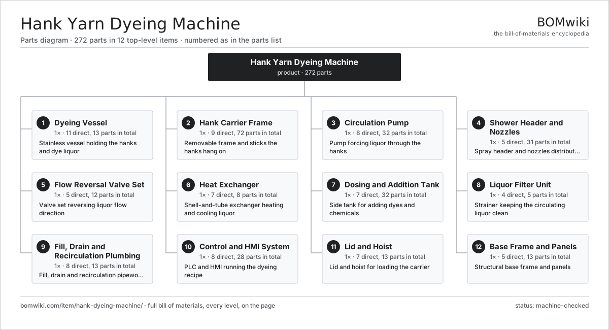
| # | Part | Qty | What it does |
|---|---|---|---|
| 1 | Dyeing Vessel 11 parts | 1× | Stainless vessel holding the hanks and dye liquor |
| 2 | Hank Carrier Frame 9 parts | 1× | Removable frame and sticks the hanks hang on |
| 3 | Circulation Pump 8 parts | 1× | Pump forcing liquor through the hanks |
| 4 | Shower Header and Nozzles 5 parts | 1× | Spray header and nozzles distributing liquor over hanks |
| 5 | Flow Reversal Valve Set 5 parts | 1× | Valve set reversing liquor flow direction |
| 6 | Heat Exchanger 7 parts | 1× | Shell-and-tube exchanger heating and cooling liquor |
| 7 | Dosing and Addition Tank 7 parts | 1× | Side tank for adding dyes and chemicals |
| 8 | Liquor Filter Unit 4 parts | 1× | Strainer keeping the circulating liquor clean |
| 9 | Fill, Drain and Recirculation Plumbing 8 parts | 1× | Fill, drain and recirculation pipework and valves |
| 10 | Control and HMI System 8 parts | 1× | PLC and HMI running the dyeing recipe |
| 11 | Lid and Hoist 7 parts | 1× | Lid and hoist for loading the carrier |
| 12 | Base Frame and Panels 5 parts | 1× | Structural base frame and panels |
3D model
No 3D model yet. Have a CAD file of this? Add a 3D model. STL renders right on this page; STEP, FreeCAD, and OpenSCAD sources are welcome too (openly licensed, like all 3D models on BOMwiki).
Build & assembly graph
expand / collapse · shared sub-assemblies converge · links to related products · est. labourTap an assembly to expand/collapse · tap a part to open it · use “Open page” for any node · drag to pan, scroll to zoom.
Bill of materials for Hank Yarn Dyeing Machine
12 top-level lines · 108 rows shown · 272 parts total · indented to 3 levels| # | Item / sub-assembly | Part no. | Qty/assy | Ext. qty | Parts | Type |
|---|---|---|---|---|---|---|
| 1 | Dyeing Vessel 11 parts | hank-dyeing-machine-dyeing-vessel | 1× | 1 | 13 | assembly |
| 1.1 | Vessel Shell | hank-dyeing-machine-vessel-shell | 1× | 1 | · | part |
| 1.2 | Dished Bottom | hank-dyeing-machine-vessel-bottom | 1× | 1 | · | part |
| 1.3 | Liquor Sump | hank-dyeing-machine-liquor-sump | 1× | 1 | · | part |
| 1.4 | Insulated Jacket | hank-dyeing-machine-vessel-jacket | 1× | 1 | · | part |
| 1.5 | Sight Glass | hank-dyeing-machine-sight-glass | 2× | 2 | · | part |
| 1.6 | Liquor Level Sensor | hank-dyeing-machine-level-sensor | 1× | 1 | · | part |
| 1.7 | Temperature Probe | hank-dyeing-machine-temperature-probe | 2× | 2 | · | part |
| 1.8 | Pressure Sensor | pressure-sensor | 1× | 1 | · | part |
| 1.9 | Lid Gasket | hank-dyeing-machine-vessel-gasket | 1× | 1 | · | part |
| 1.10 | O-Ring Set | oring-set | 1× | 1 | · | part |
| 1.11 | Fastener Set | fastener-set | 1× | 1 | · | part |
| 2 | Hank Carrier Frame 9 parts | hank-dyeing-machine-carrier-frame | 1× | 1 | 72 | assembly |
| 2.1 | Carrier End Plate | hank-dyeing-machine-carrier-side | 2× | 2 | · | part |
| 2.2 | Carrier Stick | hank-dyeing-machine-carrier-stick | 30× | 30 | · | part |
| 2.3 | Stick Support Rail | hank-dyeing-machine-stick-support | 4× | 4 | · | part |
| 2.4 | Carrier Lift Lug | hank-dyeing-machine-carrier-lift-lug | 2× | 2 | · | part |
| 2.5 | Carrier Guide | hank-dyeing-machine-carrier-guide | 4× | 4 | · | part |
| 2.6 | Carrier Drive Shaft | hank-dyeing-machine-carrier-drive-shaft | 1× | 1 | · | part |
| 2.7 | Servo Motor 4 parts | servo-motor | 1× | 1 | 24 | assembly |
| 2.7.1 | Stator Assembly 3 parts + deeper › | stator-assembly | 1× | 1 | 3 | assembly |
| 2.7.2 | Rotor Assembly 4 parts + deeper › | rotor-assembly | 1× | 1 | 19 | assembly |
| 2.7.3 | Encoder | encoder | 1× | 1 | · | part |
| 2.7.4 | Motor Housing | motor-housing | 1× | 1 | · | part |
| 2.8 | Ball Bearing | ball-bearing | 4× | 4 | · | part |
| 2.9 | Fastener Set | fastener-set | 1× | 1 | · | part |
| 3 | Circulation Pump 8 parts | hank-dyeing-machine-circulation-pump | 1× | 1 | 32 | assembly |
| 3.1 | Pump Casing | hank-dyeing-machine-pump-casing | 1× | 1 | · | part |
| 3.2 | Pump Impeller | hank-dyeing-machine-pump-impeller | 1× | 1 | · | part |
| 3.3 | Servo Motor 4 parts | servo-motor | 1× | 1 | 24 | assembly |
| 3.3.1 | Stator Assembly 3 parts + deeper › | stator-assembly | 1× | 1 | 3 | assembly |
| 3.3.2 | Rotor Assembly 4 parts + deeper › | rotor-assembly | 1× | 1 | 19 | assembly |
| 3.3.3 | Encoder | encoder | 1× | 1 | · | part |
| 3.3.4 | Motor Housing | motor-housing | 1× | 1 | · | part |
| 3.4 | Pump Shaft | hank-dyeing-machine-pump-shaft | 1× | 1 | · | part |
| 3.5 | Mechanical Seal | hank-dyeing-machine-mechanical-seal | 1× | 1 | · | part |
| 3.6 | Ball Bearing | ball-bearing | 2× | 2 | · | part |
| 3.7 | Flow Meter | hank-dyeing-machine-flow-meter | 1× | 1 | · | part |
| 3.8 | O-Ring Set | oring-set | 1× | 1 | · | part |
| 4 | Shower Header and Nozzles 5 parts | hank-dyeing-machine-shower-header | 1× | 1 | 31 | assembly |
| 4.1 | Header Manifold Pipe | hank-dyeing-machine-header-pipe | 1× | 1 | · | part |
| 4.2 | Spray Nozzle | hank-dyeing-machine-spray-nozzle | 24× | 24 | · | part |
| 4.3 | Distributor Tray | hank-dyeing-machine-distributor-tray | 1× | 1 | · | part |
| 4.4 | Header Bracket | hank-dyeing-machine-header-bracket | 4× | 4 | · | part |
| 4.5 | O-Ring Set | oring-set | 1× | 1 | · | part |
| 5 | Flow Reversal Valve Set 5 parts | hank-dyeing-machine-flow-reversal | 1× | 1 | 12 | assembly |
| 5.1 | Reversal Valve | hank-dyeing-machine-reversal-valve | 4× | 4 | · | part |
| 5.2 | Pneumatic Actuator | hank-dyeing-machine-pneumatic-actuator | 4× | 4 | · | part |
| 5.3 | Solenoid Valve Bank | hank-dyeing-machine-solenoid-bank | 1× | 1 | · | part |
| 5.4 | Pressure Sensor | pressure-sensor | 2× | 2 | · | part |
| 5.5 | O-Ring Set | oring-set | 1× | 1 | · | part |
| 6 | Heat Exchanger 7 parts | hank-dyeing-machine-heat-exchanger | 1× | 1 | 8 | assembly |
| 6.1 | Exchanger Shell | hank-dyeing-machine-hx-shell | 1× | 1 | · | part |
| 6.2 | Tube Bundle | hank-dyeing-machine-hx-tube-bundle | 1× | 1 | · | part |
| 6.3 | Tube Plate | hank-dyeing-machine-hx-tube-plate | 2× | 2 | · | part |
| 6.4 | Steam Control Valve | hank-dyeing-machine-steam-valve | 1× | 1 | · | part |
| 6.5 | Cooling Water Valve | hank-dyeing-machine-cooling-valve | 1× | 1 | · | part |
| 6.6 | Condensate Trap | hank-dyeing-machine-condensate-trap | 1× | 1 | · | part |
| 6.7 | O-Ring Set | oring-set | 1× | 1 | · | part |
| 7 | Dosing and Addition Tank 7 parts | hank-dyeing-machine-dosing-tank | 1× | 1 | 32 | assembly |
| 7.1 | Dosing Vessel | hank-dyeing-machine-dosing-vessel | 1× | 1 | · | part |
| 7.2 | Dosing Stirrer | hank-dyeing-machine-dosing-stirrer | 1× | 1 | · | part |
| 7.3 | Servo Motor 4 parts | servo-motor | 1× | 1 | 24 | assembly |
| 7.3.1 | Stator Assembly 3 parts + deeper › | stator-assembly | 1× | 1 | 3 | assembly |
| 7.3.2 | Rotor Assembly 4 parts + deeper › | rotor-assembly | 1× | 1 | 19 | assembly |
| 7.3.3 | Encoder | encoder | 1× | 1 | · | part |
| 7.3.4 | Motor Housing | motor-housing | 1× | 1 | · | part |
| 7.4 | Dosing Pump | hank-dyeing-machine-dosing-pump | 1× | 1 | · | part |
| 7.5 | Dosing Valve | hank-dyeing-machine-dosing-valve | 2× | 2 | · | part |
| 7.6 | Dosing Level Sensor | hank-dyeing-machine-dosing-level | 1× | 1 | · | part |
| 7.7 | Ball Bearing | ball-bearing | 2× | 2 | · | part |
| 8 | Liquor Filter Unit 4 parts | hank-dyeing-machine-filter-unit | 1× | 1 | 5 | assembly |
| 8.1 | Filter Housing | hank-dyeing-machine-filter-housing | 1× | 1 | · | part |
| 8.2 | Filter Basket | hank-dyeing-machine-filter-basket | 1× | 1 | · | part |
| 8.3 | Filter Screen | hank-dyeing-machine-filter-screen | 2× | 2 | · | part |
| 8.4 | O-Ring Set | oring-set | 1× | 1 | · | part |
| 9 | Fill, Drain and Recirculation Plumbing 8 parts | hank-dyeing-machine-plumbing | 1× | 1 | 13 | assembly |
| 9.1 | Fill Valve | hank-dyeing-machine-fill-valve | 2× | 2 | · | part |
| 9.2 | Drain Valve | hank-dyeing-machine-drain-valve | 1× | 1 | · | part |
| 9.3 | Recirculation Pipe | hank-dyeing-machine-recirc-pipe | 1× | 1 | · | part |
| 9.4 | Suction Pipe | hank-dyeing-machine-suction-pipe | 1× | 1 | · | part |
| 9.5 | Return Pipe | hank-dyeing-machine-return-pipe | 1× | 1 | · | part |
| 9.6 | Manual Isolation Valve | hank-dyeing-machine-manual-valve | 4× | 4 | · | part |
| 9.7 | Check Valve | hank-dyeing-machine-check-valve | 2× | 2 | · | part |
| 9.8 | O-Ring Set | oring-set | 1× | 1 | · | part |
| 10 | Control and HMI System 8 parts | hank-dyeing-machine-control-system | 1× | 1 | 28 | assembly |
| 10.1 | PLC Controller | hank-dyeing-machine-plc | 1× | 1 | · | part |
| 10.2 | HMI Touchscreen | hank-dyeing-machine-hmi | 1× | 1 | · | part |
| 10.3 | I/O Module | hank-dyeing-machine-io-module | 2× | 2 | · | part |
| 10.4 | Variable-Frequency Drive | hank-dyeing-machine-vfd | 2× | 2 | · | part |
| 10.5 | Power Supply | power-supply | 1× | 1 | · | part |
| 10.6 | Relay | relay | 8× | 8 | · | part |
| 10.7 | Wire Bundle | wire-bundle | 1× | 1 | · | part |
| 10.8 | Connector | connector | 12× | 12 | · | part |
| 11 | Lid and Hoist 7 parts | hank-dyeing-machine-lid-hoist | 1× | 1 | 13 | assembly |
| 11.1 | Vessel Lid | hank-dyeing-machine-lid | 1× | 1 | · | part |
| 11.2 | Lid Clamp | hank-dyeing-machine-lid-clamp | 6× | 6 | · | part |
| 11.3 | Lid Hinge | hank-dyeing-machine-lid-hinge | 2× | 2 | · | part |
| 11.4 | Hoist Motor | hank-dyeing-machine-hoist-motor | 1× | 1 | · | part |
| 11.5 | Hoist Hook | hank-dyeing-machine-hoist-hook | 1× | 1 | · | part |
| 11.6 | Hoist Cable | hank-dyeing-machine-hoist-cable | 1× | 1 | · | part |
| 11.7 | Safety Interlock | hank-dyeing-machine-safety-interlock | 1× | 1 | · | part |
| 12 | Base Frame and Panels 5 parts | hank-dyeing-machine-frame | 1× | 1 | 13 | assembly |
| 12.1 | Base Frame | hank-dyeing-machine-base-frame | 1× | 1 | · | part |
| 12.2 | Sheet Metal Panel | sheet-panel | 6× | 6 | · | part |
| 12.3 | Levelling Foot | hank-dyeing-machine-leveling-foot | 4× | 4 | · | part |
| 12.4 | Drip Tray | hank-dyeing-machine-drip-tray | 1× | 1 | · | part |
| 12.5 | Fastener Set | fastener-set | 1× | 1 | · | part |
Related products
same domain, ranked by shared parts Industrial Quilting Machine
1,090 parts · shares 5 with this page
Jet Dyeing Machine
263 parts · shares 5 with this page
Jigger Dyeing Machine
276 parts · shares 5 with this page
Industrial Quilting Machine
1,090 parts · shares 5 with this page
Jet Dyeing Machine
263 parts · shares 5 with this page
Jigger Dyeing Machine
276 parts · shares 5 with this page
Sourcing: possible vendors
Browse the supplier directory → Prices, MOQ, and lead times are algorithmic estimates, not quotes, and not claims about these companies. Company mappings are curated by keyword; est. price band $10k–$1M. How estimates work| Vendor | HQ | Specialty | MOQ | Lead time |
|---|---|---|---|---|
|
🇨🇭Rieter
rieter.com ↗
|
Winterthur, CH | Spinning machinery | 10 units | 14–24 wks |
| truetzschler.com ↗ | Mönchengladbach, DE | Textile machinery | 10 units | 14–24 wks |
|
🇧🇪Picanol
picanol.be ↗
|
Ypres, BE | Weaving machines | 10 units | 14–24 wks |
| karlmayer.com ↗ | Obertshausen, DE | Warp knitting machines | 10 units | 14–24 wks |
|
🇨🇭Saurer
saurer.com ↗
|
Arbon, CH | Spinning & embroidery | 10 units | 14–24 wks |
1,104-word article