Ring Spinning Frame
ProductOverview
A ring spinning frame is the machine that turns soft roving into finished single yarn, and it is still the most widely used spinning method because it makes the strongest and most even yarn across the widest count range. It does three things at once on every spindle: it draws the roving thinner to the target yarn count, it twists the drawn strand so the fibers grip one another and hold together, and it winds the twisted yarn onto a tube as a cop. A modern frame does this on five hundred to twelve hundred spindles in parallel along a single long machine, so output scales with spindle count.
Roving comes in from a Roving Creel, is drawn to count in the Drafting System system, is twisted by the Spindle Rail working with the Ring Rail, is wound to a shaped cop by the Builder Motion motion, is powered by the Main Drive, is unloaded by the Doffing System system, and is run by Control Electronics inside the Frame and Pneumafil.
The roving creel
Above the machine the Roving Creel hangs two or three rows of roving bobbins per spindle on a Creel Frame. Each bobbin sits on a swiveling Bobbin Holder so it unwinds with almost no tension, since roving is fragile and has almost no twist. A Roving Guide leads each strand down into the back of its drafting zone, and a Roving Stop Motion flags a spindle whose roving has broken or run out.
The drafting system
Drafting is where the roving is thinned to the final count. The Drafting System system uses three pairs of rollers in series. A Back Roller grips the roving and feeds it in, a Middle Roller runs faster, and a Front Roller runs faster still, so the strand is stretched between each pair. Because each pair turns faster than the one before, the fiber mass is drawn out by a factor of ten to fifty. Each bottom roller is nipped by a rubber-cot Top Roller pressed down by a sprung Weighting Arm. The critical main draft happens between the middle and front rollers, where a pair of Drafting Apron belts guide the loose floating fibers so they accelerate at the right point, which is what keeps the drawn strand even. The yarn count is set by the Draft Gear change gears that fix the roller speed ratios.
Spindles and twist insertion
As the drawn strand leaves the front roller it must be twisted at once or it will fall apart. Twisting and winding are done together by the spindle and ring. The Spindle spins a Yarn Tube at fifteen to twenty-five thousand rpm on an oil-damped Spindle Bearing. Around each spindle, fixed to the ring rail, sits a hardened Spinning Ring carrying a tiny C-shaped Traveler. The yarn runs from the front roller, through a Lappet guide, down to the traveler and onto the tube. As the spindle turns, it drags the yarn and the traveler around the ring, but the traveler lags slightly behind because of friction, and that lag is exactly what inserts twist into the yarn: each revolution the traveler falls behind puts one turn into the strand. The same rotation winds the twisted yarn onto the cop. A Balloon Separator between spindles keeps neighboring yarn balloons from touching. Spindles are driven in groups by flat Drive Tape belts tensioned by Jockey Pulley units.
Cop building
To wind a cop that will unwind cleanly later, the Ring Rail must move up and down as the yarn winds. The Builder Motion motion does this with a Builder Cam profile and a Builder Servo that drive the Ring Rail Beam up the Ball Screw lifts on Poker Bar guides. Each traverse is slightly shorter and higher than the last, which lays the yarn in tapered conical layers and gives the cop its characteristic nose so it can be overend-unwound at high speed downstream.
Drive, doffing and control
The Main Drive uses a Main Motor driving a full-length Tin Roller through a Gearbox Housing and Helical Gear Pair sets, so spindle speed and roller speed hold a fixed ratio that sets the twist per inch. When the cops are full, the Doffing System system lifts them all off at once: a Doffer Bar of Tube Gripper clamps, driven by a Doffer Servo, pulls full cops and seats empty tubes across every spindle in one cycle. The Control Electronics sets count, twist and speed through an Microcontroller, a Variable Speed Drive pair, a Power Supply and the Operator Panel panel, and the Pneumafil suction at the front rollers catches the fiber whenever an end breaks so it cannot lap the rollers.
Yarn, variants and use
Ring spinning makes the strongest yarn per unit twist of any common system, which is why it dominates fine-count combed cotton, blends and high-quality knitting and weaving yarns from about Ne 6 down to Ne 80 and finer. Compact spinning is a variant that adds a suction zone after the front roller to condense the fiber ribbon before twist, which cuts hairiness and lifts strength further. The trade against rotor and air-jet spinning is speed: ring spinning is slower per spindle, so it competes on quality and count range rather than raw throughput.
Ring Spinning Frame parts and their functions
9 top-level parts · 11,740 parts in total · full bill of materials below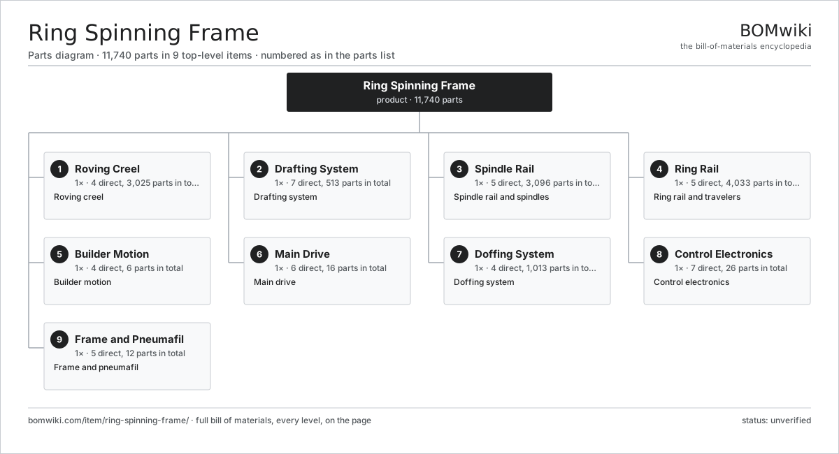
| # | Part | Qty | What it does |
|---|---|---|---|
| 1 | Roving Creel 4 parts | 1× | Roving creel |
| 2 | Drafting System 7 parts | 1× | Drafting system |
| 3 | Spindle Rail 5 parts | 1× | Spindle rail and spindles |
| 4 | Ring Rail 5 parts | 1× | Ring rail and travelers |
| 5 | Builder Motion 4 parts | 1× | Builder motion |
| 6 | Main Drive 6 parts | 1× | Main drive |
| 7 | Doffing System 4 parts | 1× | Doffing system |
| 8 | Control Electronics 7 parts | 1× | Control electronics |
| 9 | Frame and Pneumafil 5 parts | 1× | Frame and pneumafil |
3D model
No 3D model yet. Have a CAD file of this? Add a 3D model. STL renders right on this page; STEP, FreeCAD, and OpenSCAD sources are welcome too (openly licensed, like all 3D models on BOMwiki).
Build & assembly graph
expand / collapse · shared sub-assemblies converge · links to related products · est. labourTap an assembly to expand/collapse · tap a part to open it · use “Open page” for any node · drag to pan, scroll to zoom.
Bill of materials for Ring Spinning Frame
9 top-level lines · 56 rows shown · 11,740 parts total · indented to 3 levels| # | Item / sub-assembly | Part no. | Qty/assy | Ext. qty | Parts | Type |
|---|---|---|---|---|---|---|
| 1 | Roving Creel 4 parts | ring-spinning-frame-creel | 1× | 1 | 3,025 | assembly |
| 1.1 | Creel Frame | ring-spinning-frame-creel-frame | 1× | 1 | · | part |
| 1.2 | Bobbin Holder | ring-spinning-frame-bobbin-holder | 1008× | 1,008 | · | part |
| 1.3 | Roving Guide | ring-spinning-frame-roving-guide | 1008× | 1,008 | · | part |
| 1.4 | Roving Stop Motion | ring-spinning-frame-stop-motion | 1008× | 1,008 | · | part |
| 2 | Drafting System 7 parts | ring-spinning-frame-drafting | 1× | 1 | 513 | assembly |
| 2.1 | Back Roller | ring-spinning-frame-back-roller | 1× | 1 | · | part |
| 2.2 | Middle Roller | ring-spinning-frame-middle-roller | 1× | 1 | · | part |
| 2.3 | Front Roller | ring-spinning-frame-front-roller | 1× | 1 | · | part |
| 2.4 | Top Roller | ring-spinning-frame-top-roller | 3× | 3 | · | part |
| 2.5 | Drafting Apron | ring-spinning-frame-apron | 2× | 2 | · | part |
| 2.6 | Weighting Arm | ring-spinning-frame-weighting-arm | 504× | 504 | · | part |
| 2.7 | Draft Gear | ring-spinning-frame-draft-gear | 1× | 1 | · | part |
| 3 | Spindle Rail 5 parts | ring-spinning-frame-spindle-rail | 1× | 1 | 3,096 | assembly |
| 3.1 | Spindle | ring-spinning-frame-spindle | 1008× | 1,008 | · | part |
| 3.2 | Spindle Bearing | ring-spinning-frame-spindle-bearing | 1008× | 1,008 | · | part |
| 3.3 | Yarn Tube | ring-spinning-frame-tube | 1008× | 1,008 | · | part |
| 3.4 | Drive Tape | ring-spinning-frame-tape | 8× | 8 | · | part |
| 3.5 | Jockey Pulley | ring-spinning-frame-jockey-pulley | 64× | 64 | · | part |
| 4 | Ring Rail 5 parts | ring-spinning-frame-ring-rail | 1× | 1 | 4,033 | assembly |
| 4.1 | Spinning Ring | ring-spinning-frame-ring | 1008× | 1,008 | · | part |
| 4.2 | Traveler | ring-spinning-frame-traveler | 1008× | 1,008 | · | part |
| 4.3 | Lappet | ring-spinning-frame-lappet | 1008× | 1,008 | · | part |
| 4.4 | Balloon Separator | ring-spinning-frame-separator | 1008× | 1,008 | · | part |
| 4.5 | Ring Rail Beam | ring-spinning-frame-rail-beam | 1× | 1 | · | part |
| 5 | Builder Motion 4 parts | ring-spinning-frame-builder | 1× | 1 | 6 | assembly |
| 5.1 | Builder Cam | ring-spinning-frame-builder-cam | 1× | 1 | · | part |
| 5.2 | Builder Servo | ring-spinning-frame-builder-servo | 1× | 1 | · | part |
| 5.3 | Ball Screw | ball-screw | 2× | 2 | · | part |
| 5.4 | Poker Bar | ring-spinning-frame-poker-bar | 2× | 2 | · | part |
| 6 | Main Drive 6 parts | ring-spinning-frame-drive | 1× | 1 | 16 | assembly |
| 6.1 | Main Motor | ring-spinning-frame-main-motor | 1× | 1 | · | part |
| 6.2 | Tin Roller | ring-spinning-frame-tin-roller | 1× | 1 | · | part |
| 6.3 | Gearbox Housing | gearbox-housing | 1× | 1 | · | part |
| 6.4 | Helical Gear Pair | gear-pair | 4× | 4 | · | part |
| 6.5 | Drive Belt | drive-belt | 1× | 1 | · | part |
| 6.6 | Ball Bearing | ball-bearing | 8× | 8 | · | part |
| 7 | Doffing System 4 parts | ring-spinning-frame-doffing | 1× | 1 | 1,013 | assembly |
| 7.1 | Doffer Bar | ring-spinning-frame-doffer-bar | 1× | 1 | · | part |
| 7.2 | Tube Gripper | ring-spinning-frame-gripper | 1008× | 1,008 | · | part |
| 7.3 | Doffer Servo | ring-spinning-frame-doffer-servo | 2× | 2 | · | part |
| 7.4 | Linear Guide Rail | linear-guide | 2× | 2 | · | part |
| 8 | Control Electronics 7 parts | ring-spinning-frame-control | 1× | 1 | 26 | assembly |
| 8.1 | Microcontroller | mcu | 1× | 1 | · | part |
| 8.2 | Bare PCB | pcb-bare | 2× | 2 | · | part |
| 8.3 | Operator Panel | ring-spinning-frame-touchscreen | 1× | 1 | · | part |
| 8.4 | Power Supply | power-supply | 1× | 1 | · | part |
| 8.5 | Variable Speed Drive | ring-spinning-frame-vfd | 2× | 2 | · | part |
| 8.6 | Wire Bundle | wire-bundle | 1× | 1 | · | part |
| 8.7 | Connector | connector | 18× | 18 | · | part |
| 9 | Frame and Pneumafil 5 parts | ring-spinning-frame-frame | 1× | 1 | 12 | assembly |
| 9.1 | Frame Weldment | ring-spinning-frame-frame-weldment | 1× | 1 | · | part |
| 9.2 | Pneumafil | ring-spinning-frame-pneumafil | 1× | 1 | · | part |
| 9.3 | Suction Fan | ring-spinning-frame-suction-fan | 1× | 1 | · | part |
| 9.4 | Sheet Metal Panel | sheet-panel | 8× | 8 | · | part |
| 9.5 | Fastener Set | fastener-set | 1× | 1 | · | part |
Related products
same domain, ranked by shared parts Automatic Fabric Cutting Machine
1,695 parts · shares 4 with this page
Fabric Coating Machine
316 parts · shares 4 with this page
Automatic Fabric Cutting Machine
1,695 parts · shares 4 with this page
Fabric Coating Machine
316 parts · shares 4 with this page
 Industrial Quilting Machine
1,090 parts · shares 4 with this page
Laser Fabric Cutting Machine
297 parts · shares 4 with this page
Industrial Quilting Machine
1,090 parts · shares 4 with this page
Laser Fabric Cutting Machine
297 parts · shares 4 with this page
 Meltblown Nonwoven Line
933 parts · shares 4 with this page
Meltblown Nonwoven Line
933 parts · shares 4 with this page
 Rotary Screen Textile Printer
3,441 parts · shares 4 with this page
Rotary Screen Textile Printer
3,441 parts · shares 4 with this page
Sourcing: possible vendors
Browse the supplier directory → Prices, MOQ, and lead times are algorithmic estimates, not quotes, and not claims about these companies. Company mappings are curated by keyword; est. price band $10k–$1M. How estimates work| Vendor | HQ | Specialty | MOQ | Lead time |
|---|---|---|---|---|
|
🇨🇭Rieter
rieter.com ↗
|
Winterthur, CH | Spinning machinery | 10 units | 14–24 wks |
| truetzschler.com ↗ | Mönchengladbach, DE | Textile machinery | 10 units | 14–24 wks |
|
🇧🇪Picanol
picanol.be ↗
|
Ypres, BE | Weaving machines | 10 units | 14–24 wks |
| karlmayer.com ↗ | Obertshausen, DE | Warp knitting machines | 10 units | 14–24 wks |
|
🇨🇭Saurer
saurer.com ↗
|
Arbon, CH | Spinning & embroidery | 10 units | 14–24 wks |
1,004-word article