Jigger Dyeing Machine
ProductOverview
A jigger (or jig) dyeing machine dyes woven fabric in open width, meaning the cloth runs flat at its full width rather than in rope form. The full piece is wound onto one of two large batch rollers and then driven across the machine, dipping through a V-shaped dye trough that holds the dye liquor, and rewound onto the second batch roller. When the whole batch has transferred from one roller to the other, that counts as one end or one pass. The drive then reverses and the fabric runs back, making repeated passes until the shade is built up evenly. The machine works at a low liquor ratio of roughly 1:2 to 1:4, so it uses less water, dye and energy than rope or winch dyeing for the same weight of cloth.
Jiggers suit woven goods that would crease or distort in rope form, such as suiting, shirting, lining and many industrial fabrics. Because the cloth is handled flat under controlled tension, the jigger gives level dyeing with low risk of crease marks. It is a batch machine, so it is well matched to small and medium lots and to frequent shade changes.
How it works
The operator loads the prepared fabric onto one batch roller and threads it down through the trough, under the immersion roller that holds it submerged, over the guide rollers, and up onto the empty batch roller. The trough is filled with liquor and brought to temperature by the steam heating system, which modulates a steam valve against bath temperature probes. The main drive then turns the take-up roller; the cloth unwinds from the first roller, passes through the dye liquor and winds onto the second.
Each layer of fabric on the roller has a slightly larger diameter than the last, so a fixed roller speed would change the linear fabric speed and the dwell time in the bath. The drive and the tension control compensate for this by adjusting roller speed and back-tension as the batch diameter grows and shrinks, keeping fabric speed and tension steady. The controller counts ends with the drive encoders and runs the recipe: it adds dye and salt through the dosing pumps at set points, ramps temperature, and stops at the programmed number of passes.
Subsystems
The dye trough is a V-section 316L stainless bath with a submerged steam coil, a level sensor and a large drain valve for dropping the spent bath. The two batch roller assemblies carry the fabric and are the only items that change diameter through a run; each rides on bearings sealed against liquor by oil seals. The guide and immersion roller set routes the web through the liquor and keeps it spread flat with a curved spreader roller.
The main drive uses two servo motors, one per batch roller, through reduction gearboxes; one motor winds while the other pays out under controlled tension, and they swap roles on every pass. The tension system reads web tension with a dancer roller and load cells and trims a magnetic-particle brake so the cloth stays flat and crease-free as the roll diameter changes. The fabric guiding and expander centres the web and opens it to full width before it rewinds.
The liquor circulation and dosing system runs a corrosion-resistant circulation pump for even shade and meters dye, salt and alkali from an addition tank. The control system is built around a PLC and a touchscreen HMI; it counts ends, runs temperature and dosing profiles, and supervises tension. Everything sits on a welded frame with side stands at working height.
Materials and construction
All wetted parts see hot, often acidic or alkaline, dye liquor, so the trough, rollers and pipework are stainless steel, typically 316L, and the trough may carry an extra corrosion-resistant liner. Batch rollers are either bare stainless or rubber covered for grip. Bearings and shafts that pass near the bath are protected by lip seals, and on the HT machine the roller shafts pass through sealed stuffing boxes in the vessel wall. Frames are welded carbon steel, painted or galvanised, with stainless splash covers over the trough.
Atmospheric and HT variants
The standard machine is open and works at atmospheric pressure, so its top dyeing temperature is about 98 degrees C, which suits cotton with reactive and direct dyes. To dye polyester and polyester blends, the fibre must be opened at higher temperature, so the high-temperature (HT) jigger encloses the rollers and trough inside a sealed pressure shell. The shell holds saturated steam pressure up to roughly 3.6 bar, letting the bath reach 135 to 140 degrees C. The HT version adds a quick-locking access door with a high-temperature seal, a safety relief valve, a vessel pressure sensor and sealed shaft pass-throughs so the rollers can be driven from outside the pressure boundary.
Use and operation
A typical run loads a prepared batch, fills and heats the trough, then runs the cloth back and forth for the programmed number of ends while dye and chemicals are dosed on profile. The controller logs temperature, tension and pass count so the shade is repeatable from lot to lot. Because the cloth is wound on rollers and never twisted into rope, the jigger is the preferred batch machine for woven goods that must stay flat and crease-free, and its low liquor ratio keeps water, salt and effluent down compared with older winch and beck dyeing.
Jigger Dyeing Machine parts and their functions
11 top-level parts · 276 parts in total · full bill of materials below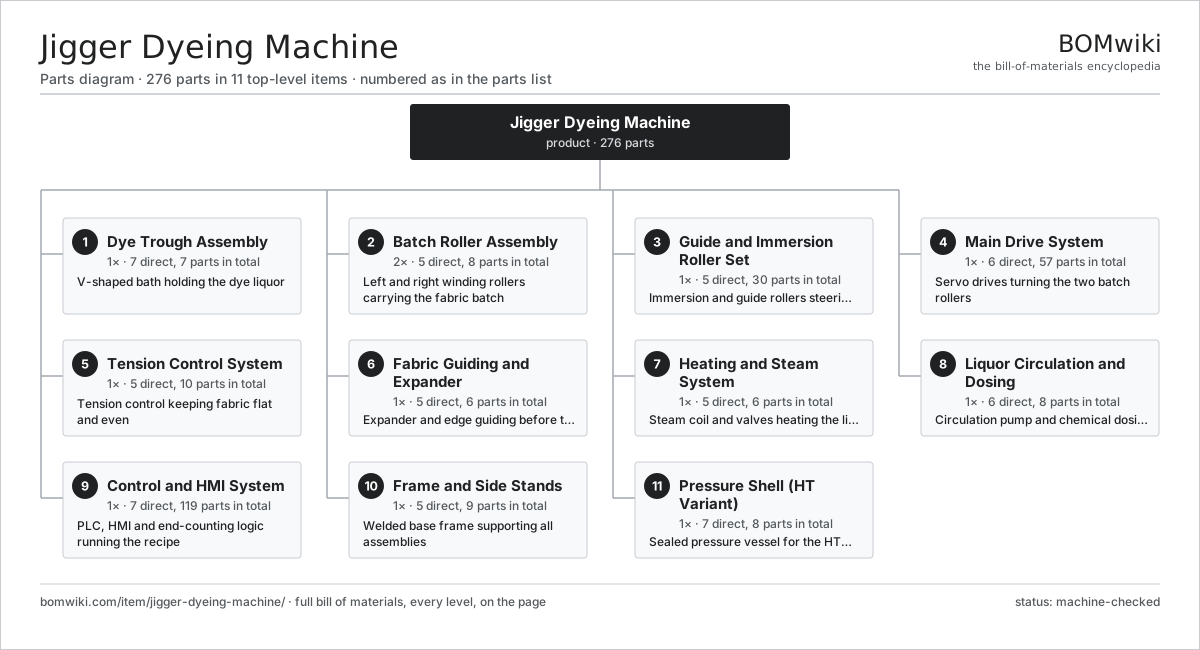
| # | Part | Qty | What it does |
|---|---|---|---|
| 1 | Dye Trough Assembly 7 parts | 1× | V-shaped bath holding the dye liquor |
| 2 | Batch Roller Assembly 5 parts | 2× | Left and right winding rollers carrying the fabric batch |
| 3 | Guide and Immersion Roller Set 5 parts | 1× | Immersion and guide rollers steering fabric through the bath |
| 4 | Main Drive System 6 parts | 1× | Servo drives turning the two batch rollers |
| 5 | Tension Control System 5 parts | 1× | Tension control keeping fabric flat and even |
| 6 | Fabric Guiding and Expander 5 parts | 1× | Expander and edge guiding before the batch roller |
| 7 | Heating and Steam System 5 parts | 1× | Steam coil and valves heating the liquor |
| 8 | Liquor Circulation and Dosing 6 parts | 1× | Circulation pump and chemical dosing |
| 9 | Control and HMI System 7 parts | 1× | PLC, HMI and end-counting logic running the recipe |
| 10 | Frame and Side Stands 5 parts | 1× | Welded base frame supporting all assemblies |
| 11 | Pressure Shell (HT Variant) 7 parts | 1× | Sealed pressure vessel for the HT enclosed variant |
3D model
No 3D model yet. Have a CAD file of this? Add a 3D model. STL renders right on this page; STEP, FreeCAD, and OpenSCAD sources are welcome too (openly licensed, like all 3D models on BOMwiki).
Build & assembly graph
expand / collapse · shared sub-assemblies converge · links to related products · est. labourTap an assembly to expand/collapse · tap a part to open it · use “Open page” for any node · drag to pan, scroll to zoom.
Bill of materials for Jigger Dyeing Machine
11 top-level lines · 86 rows shown · 276 parts total · indented to 3 levels| # | Item / sub-assembly | Part no. | Qty/assy | Ext. qty | Parts | Type |
|---|---|---|---|---|---|---|
| 1 | Dye Trough Assembly 7 parts | jigger-dyeing-machine-dye-trough | 1× | 1 | 7 | assembly |
| 1.1 | Trough Body | jigger-dyeing-machine-trough-body | 1× | 1 | · | part |
| 1.2 | Trough Liner | jigger-dyeing-machine-trough-liner | 1× | 1 | · | part |
| 1.3 | Steam Heating Coil | jigger-dyeing-machine-steam-coil | 1× | 1 | · | part |
| 1.4 | Bath Drain Valve | jigger-dyeing-machine-drain-valve | 1× | 1 | · | part |
| 1.5 | Overflow Weir | jigger-dyeing-machine-overflow-weir | 1× | 1 | · | part |
| 1.6 | Liquor Level Sensor | jigger-dyeing-machine-level-sensor | 1× | 1 | · | part |
| 1.7 | Fastener Set | fastener-set | 1× | 1 | · | part |
| 2 | Batch Roller Assembly 5 parts | jigger-dyeing-machine-batch-roller-assy | 2× | 2 | 8 | assembly |
| 2.1 | Batch Roller | jigger-dyeing-machine-batch-roller | 1× | 2 | · | part |
| 2.2 | Roller Journal | jigger-dyeing-machine-roller-journal | 2× | 4 | · | part |
| 2.3 | Ball Bearing | ball-bearing | 2× | 4 | · | part |
| 2.4 | Roller Coupling | jigger-dyeing-machine-roller-coupling | 1× | 2 | · | part |
| 2.5 | Oil Seal | oil-seal | 2× | 4 | · | part |
| 3 | Guide and Immersion Roller Set 5 parts | jigger-dyeing-machine-guide-roller-set | 1× | 1 | 30 | assembly |
| 3.1 | Immersion Roller | jigger-dyeing-machine-immersion-roller | 1× | 1 | · | part |
| 3.2 | Guide Roller | jigger-dyeing-machine-guide-roller | 4× | 4 | · | part |
| 3.3 | Spreader Roller | jigger-dyeing-machine-spreader-roller | 1× | 1 | · | part |
| 3.4 | Ball Bearing | ball-bearing | 12× | 12 | · | part |
| 3.5 | Oil Seal | oil-seal | 12× | 12 | · | part |
| 4 | Main Drive System 6 parts | jigger-dyeing-machine-main-drive | 1× | 1 | 57 | assembly |
| 4.1 | Servo Motor 4 parts | servo-motor | 2× | 2 | 24 | assembly |
| 4.1.1 | Stator Assembly 3 parts + deeper › | stator-assembly | 1× | 2 | 3 | assembly |
| 4.1.2 | Rotor Assembly 4 parts + deeper › | rotor-assembly | 1× | 2 | 19 | assembly |
| 4.1.3 | Encoder | encoder | 1× | 2 | · | part |
| 4.1.4 | Motor Housing | motor-housing | 1× | 2 | · | part |
| 4.2 | Gearbox Housing | gearbox-housing | 2× | 2 | · | part |
| 4.3 | Drive Shaft | jigger-dyeing-machine-drive-shaft | 2× | 2 | · | part |
| 4.4 | Drive Belt | drive-belt | 2× | 2 | · | part |
| 4.5 | Encoder | encoder | 2× | 2 | · | part |
| 4.6 | Drive Guard | jigger-dyeing-machine-drive-guard | 1× | 1 | · | part |
| 5 | Tension Control System 5 parts | jigger-dyeing-machine-tension-system | 1× | 1 | 10 | assembly |
| 5.1 | Dancer Roller | jigger-dyeing-machine-dancer-roller | 1× | 1 | · | part |
| 5.2 | Tension Load Cell | jigger-dyeing-machine-load-cell | 2× | 2 | · | part |
| 5.3 | Tension Brake Unit | jigger-dyeing-machine-brake-unit | 1× | 1 | · | part |
| 5.4 | Coil Spring | coil-spring | 2× | 2 | · | part |
| 5.5 | Ball Bearing | ball-bearing | 4× | 4 | · | part |
| 6 | Fabric Guiding and Expander 5 parts | jigger-dyeing-machine-fabric-guiding | 1× | 1 | 6 | assembly |
| 6.1 | Edge Guide Unit | jigger-dyeing-machine-edge-guide | 1× | 1 | · | part |
| 6.2 | Expander Bow | jigger-dyeing-machine-expander-bow | 1× | 1 | · | part |
| 6.3 | Guide Actuator | jigger-dyeing-machine-guide-actuator | 1× | 1 | · | part |
| 6.4 | Hall Sensor | hall-sensor | 2× | 2 | · | part |
| 6.5 | Fastener Set | fastener-set | 1× | 1 | · | part |
| 7 | Heating and Steam System 5 parts | jigger-dyeing-machine-heating-system | 1× | 1 | 6 | assembly |
| 7.1 | Steam Control Valve | jigger-dyeing-machine-steam-valve | 1× | 1 | · | part |
| 7.2 | Steam Trap | jigger-dyeing-machine-steam-trap | 1× | 1 | · | part |
| 7.3 | Bath Temperature Probe | jigger-dyeing-machine-temp-probe | 2× | 2 | · | part |
| 7.4 | Steam Strainer | jigger-dyeing-machine-steam-strainer | 1× | 1 | · | part |
| 7.5 | O-Ring Set | oring-set | 1× | 1 | · | part |
| 8 | Liquor Circulation and Dosing 6 parts | jigger-dyeing-machine-liquor-system | 1× | 1 | 8 | assembly |
| 8.1 | Circulation Pump | jigger-dyeing-machine-circ-pump | 1× | 1 | · | part |
| 8.2 | Dosing Pump | jigger-dyeing-machine-dosing-pump | 2× | 2 | · | part |
| 8.3 | Addition Tank | jigger-dyeing-machine-addition-tank | 1× | 1 | · | part |
| 8.4 | Flow Meter | jigger-dyeing-machine-flow-meter | 1× | 1 | · | part |
| 8.5 | Ball Bearing | ball-bearing | 2× | 2 | · | part |
| 8.6 | O-Ring Set | oring-set | 1× | 1 | · | part |
| 9 | Control and HMI System 7 parts | jigger-dyeing-machine-control-system | 1× | 1 | 119 | assembly |
| 9.1 | PLC Controller 4 parts | jigger-dyeing-machine-plc | 1× | 1 | 84 | assembly |
| 9.1.1 | Bare PCB | pcb-bare | 1× | 1 | · | part |
| 9.1.2 | Microcontroller | mcu | 1× | 1 | · | part |
| 9.1.3 | SMD Passive (R/C/L) | smd-passives | 80× | 80 | · | part |
| 9.1.4 | I/O Module | jigger-dyeing-machine-io-module | 2× | 2 | · | part |
| 9.2 | HMI Touch Panel 4 parts | jigger-dyeing-machine-hmi-panel | 1× | 1 | 4 | assembly |
| 9.2.1 | LCD Panel | lcd-panel | 1× | 1 | · | part |
| 9.2.2 | Touch Digitizer | touch-digitizer | 1× | 1 | · | part |
| 9.2.3 | Compute SoC Module | soc-module | 1× | 1 | · | part |
| 9.2.4 | Bare PCB | pcb-bare | 1× | 1 | · | part |
| 9.3 | Power Supply | power-supply | 1× | 1 | · | part |
| 9.4 | Relay | relay | 8× | 8 | · | part |
| 9.5 | Pressure Sensor | pressure-sensor | 1× | 1 | · | part |
| 9.6 | Wire Bundle | wire-bundle | 1× | 1 | · | part |
| 9.7 | Connector | connector | 20× | 20 | · | part |
| 10 | Frame and Side Stands 5 parts | jigger-dyeing-machine-frame | 1× | 1 | 9 | assembly |
| 10.1 | Base Frame | jigger-dyeing-machine-base-frame | 1× | 1 | · | part |
| 10.2 | Side Stand | jigger-dyeing-machine-side-stand | 2× | 2 | · | part |
| 10.3 | Sheet Metal Panel | sheet-panel | 4× | 4 | · | part |
| 10.4 | Splash Cover | jigger-dyeing-machine-splash-cover | 1× | 1 | · | part |
| 10.5 | Fastener Set | fastener-set | 1× | 1 | · | part |
| 11 | Pressure Shell (HT Variant) 7 parts | jigger-dyeing-machine-pressure-shell | 1× | 1 | 8 | assembly |
| 11.1 | Shell Body | jigger-dyeing-machine-shell-body | 1× | 1 | · | part |
| 11.2 | Access Door | jigger-dyeing-machine-shell-door | 1× | 1 | · | part |
| 11.3 | Door Seal | jigger-dyeing-machine-door-seal | 1× | 1 | · | part |
| 11.4 | Safety Relief Valve | jigger-dyeing-machine-safety-valve | 1× | 1 | · | part |
| 11.5 | Pressure Sensor | pressure-sensor | 1× | 1 | · | part |
| 11.6 | Shaft Stuffing Box | jigger-dyeing-machine-stuffing-box | 2× | 2 | · | part |
| 11.7 | Fastener Set | fastener-set | 1× | 1 | · | part |
Related products
same domain, ranked by shared parts Textile Stenter Frame
1,683 parts · shares 10 with this page
Spunlace Nonwoven Line
1,735 parts · shares 9 with this page
Textile Calendering Machine
623 parts · shares 9 with this page
Textile Stenter Frame
1,683 parts · shares 10 with this page
Spunlace Nonwoven Line
1,735 parts · shares 9 with this page
Textile Calendering Machine
623 parts · shares 9 with this page
Sourcing: possible vendors
Browse the supplier directory → Prices, MOQ, and lead times are algorithmic estimates, not quotes, and not claims about these companies. Company mappings are curated by keyword; est. price band $10k–$1M. How estimates work| Vendor | HQ | Specialty | MOQ | Lead time |
|---|---|---|---|---|
|
🇨🇭Rieter
rieter.com ↗
|
Winterthur, CH | Spinning machinery | 10 units | 14–24 wks |
| truetzschler.com ↗ | Mönchengladbach, DE | Textile machinery | 10 units | 14–24 wks |
|
🇧🇪Picanol
picanol.be ↗
|
Ypres, BE | Weaving machines | 10 units | 14–24 wks |
| karlmayer.com ↗ | Obertshausen, DE | Warp knitting machines | 10 units | 14–24 wks |
|
🇨🇭Saurer
saurer.com ↗
|
Arbon, CH | Spinning & embroidery | 10 units | 14–24 wks |
1,035-word article