Textile Draw Frame
ProductOverview
A draw frame is the machine that makes spinning-room sliver even. The card delivers a sliver that is reasonably clean but uneven in thickness and full of hooked and crossed fibers. If that sliver went straight to spinning the yarn would vary in count and strength along its length. The draw frame fixes this in two ways at once: it doubles several slivers together so their thick and thin places average out, and it drafts the combined strand back down to a single sliver while straightening the fibers along the way.
Drawing is usually done in one or two passes. The first passage blends and parallelises, and a second passage, often called the finisher draw frame, brings the evenness up to the level spinning needs. On a modern machine the second pass carries an auto-leveller that watches the strand and corrects its thickness as it runs, which is what lets one draw frame replace the several passages older machines needed.
Doubling and drafting
Six to eight slivers from the Sliver Creel & Feed feed into the machine side by side. Doubling is the simple part: a thin place in one sliver lands next to a thick place in another, so the combined strand is steadier than any single feed. The Drafting System system then pulls that combined strand out to a fraction of its fed thickness. A set of bottom rollers turn at rising speed from back to front, and the Bottom Drafting Roller front pair runs fastest, so the strand is stretched between the nips. Rubber-covered Top Pressure Roller rollers pressed down by the Top Roller Pressure Arm grip the fibers so the draft acts on every fiber and not just the surface. As the fibers slide past one another in the draft zone their hooks pull straight, which is the other reason drawing matters: straight parallel fibers make stronger, smoother yarn.
The total draft roughly equals the number of doublings, so the sliver that leaves is about the same weight per metre as one that came in, but far more even and far better aligned.
Auto-levelling
The single biggest improvement on a modern draw frame is the Auto-Leveller. At the feed, the doubled slivers pass through a spring-loaded Measuring Funnel whose opening tracks the strand thickness. A Thickness Displacement Sensor reads that opening and turns it into a signal of how much fiber is coming. The Leveller Controller takes this signal, delays it by exactly the time the strand takes to travel from the funnel to the draft zone, and then commands the Draft Correction Servo to vary the draft on the fly. A thick place arriving at the rollers gets drafted more, a thin place less. The output sliver comes out level metre to metre, which is the property that decides the evenness of the final yarn. A delivery funnel checks the levelled strand and logs any residual variation for the quality department.
Coiling and can changing
The even sliver is too bulky and delicate to wind, so it is coiled into a tall can instead. The Sliver Coiler head spins above the can: the sliver passes through a curved Coiler Tube carried on a turning plate, which lays it in overlapping coils, while the Can Turntable rotates the can slowly so each layer shifts and the can fills evenly without tangling. A pair of calender rollers lightly compacts the sliver first so it holds its coil.
When the can reaches its set length the Can Changer swaps it for an empty one automatically. A length counter triggers the change, a pusher arm rolls the full can out onto the transfer track and pulls the next empty can from the magazine into place, all without stopping the machine for long.
Suction and cleanliness
Drafting throws off a lot of fiber fly, and a draw frame runs fast, so the Suction & Waste System system is always on. A fan pulls air through pickup mouths over the rollers and at the broken-end point, carrying fly and trimmings down the ducting to a waste box, while a filter drum separates the fiber so clean air returns to the room. Keeping the draft zone clean matters because a lump of fly drawn into the strand would show up as a fault.
Materials and use
The bottom rollers are case-hardened steel for wear life under constant fiber abrasion, the top rollers carry replaceable rubber cots, and the base and head housing are cast iron because mass damps the vibration that high delivery speeds would otherwise cause. The Machine Control cabinet sets draft, speed and leveller behaviour from a touchscreen and logs evenness data.
Every cotton and blended-fiber spinning mill runs draw frames between carding and the roving or spinning stage. The quality of the sliver they deliver sets a ceiling on the quality of the yarn, so the draw frame, though it is one of the quieter machines in the room, is one of the ones the mill watches most closely.
Textile Draw Frame parts and their functions
10 top-level parts · 231 parts in total · full bill of materials below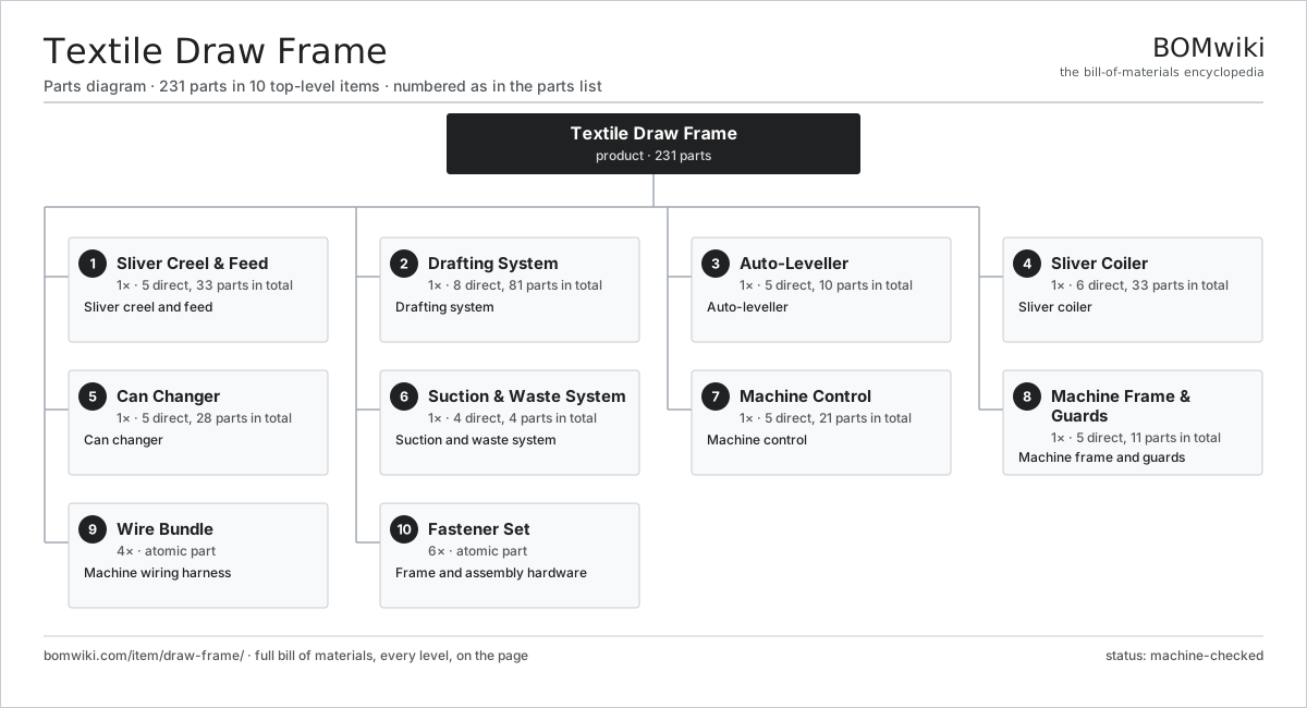
| # | Part | Qty | What it does |
|---|---|---|---|
| 1 | Sliver Creel & Feed 5 parts | 1× | Sliver creel and feed |
| 2 | Drafting System 8 parts | 1× | Drafting system |
| 3 | Auto-Leveller 5 parts | 1× | Auto-leveller |
| 4 | Sliver Coiler 6 parts | 1× | Sliver coiler |
| 5 | Can Changer 5 parts | 1× | Can changer |
| 6 | Suction & Waste System 4 parts | 1× | Suction and waste system |
| 7 | Machine Control 5 parts | 1× | Machine control |
| 8 | Machine Frame & Guards 5 parts | 1× | Machine frame and guards |
| 9 | Wire Bundle | 4× | Machine wiring harness |
| 10 | Fastener Set | 6× | Frame and assembly hardware |
3D model
No 3D model yet. Have a CAD file of this? Add a 3D model. STL renders right on this page; STEP, FreeCAD, and OpenSCAD sources are welcome too (openly licensed, like all 3D models on BOMwiki).
Build & assembly graph
expand / collapse · shared sub-assemblies converge · links to related products · est. labourTap an assembly to expand/collapse · tap a part to open it · use “Open page” for any node · drag to pan, scroll to zoom.
Bill of materials for Textile Draw Frame
10 top-level lines · 77 rows shown · 231 parts total · indented to 3 levels| # | Item / sub-assembly | Part no. | Qty/assy | Ext. qty | Parts | Type |
|---|---|---|---|---|---|---|
| 1 | Sliver Creel & Feed 5 parts | draw-frame-creel | 1× | 1 | 33 | assembly |
| 1.1 | Creel Guide Roller | draw-frame-creel-roller | 8× | 8 | · | part |
| 1.2 | Sliver Guide | draw-frame-sliver-guide | 8× | 8 | · | part |
| 1.3 | Feed Stop-Motion Sensor | draw-frame-feed-sensor | 8× | 8 | · | part |
| 1.4 | Creel Frame | draw-frame-creel-frame | 1× | 1 | · | part |
| 1.5 | Ball Bearing | ball-bearing | 8× | 8 | · | part |
| 2 | Drafting System 8 parts | draw-frame-drafting | 1× | 1 | 81 | assembly |
| 2.1 | Bottom Drafting Roller | draw-frame-bottom-roller | 4× | 4 | · | part |
| 2.2 | Top Pressure Roller | draw-frame-top-roller | 4× | 4 | · | part |
| 2.3 | Top Roller Pressure Arm | draw-frame-pressure-arm | 1× | 1 | · | part |
| 2.4 | Draft Change Gearbox 4 parts | draw-frame-draft-gearbox | 1× | 1 | 11 | assembly |
| 2.4.1 | Gearbox Housing | gearbox-housing | 1× | 1 | · | part |
| 2.4.2 | Helical Gear Pair | gear-pair | 4× | 4 | · | part |
| 2.4.3 | Ball Bearing | ball-bearing | 4× | 4 | · | part |
| 2.4.4 | Oil Seal | oil-seal | 2× | 2 | · | part |
| 2.5 | Top Roller Clearer | draw-frame-clearer-roller | 2× | 2 | · | part |
| 2.6 | Helical Gear Pair | gear-pair | 3× | 3 | · | part |
| 2.7 | Servo Motor 4 parts | servo-motor | 2× | 2 | 24 | assembly |
| 2.7.1 | Stator Assembly 3 parts + deeper › | stator-assembly | 1× | 2 | 3 | assembly |
| 2.7.2 | Rotor Assembly 4 parts + deeper › | rotor-assembly | 1× | 2 | 19 | assembly |
| 2.7.3 | Encoder | encoder | 1× | 2 | · | part |
| 2.7.4 | Motor Housing | motor-housing | 1× | 2 | · | part |
| 2.8 | Ball Bearing | ball-bearing | 8× | 8 | · | part |
| 3 | Auto-Leveller 5 parts | draw-frame-autoleveller | 1× | 1 | 10 | assembly |
| 3.1 | Measuring Funnel | draw-frame-measuring-funnel | 1× | 1 | · | part |
| 3.2 | Thickness Displacement Sensor | draw-frame-displacement-sensor | 1× | 1 | · | part |
| 3.3 | Leveller Controller 4 parts | draw-frame-leveller-controller | 1× | 1 | 6 | assembly |
| 3.3.1 | Bare PCB | pcb-bare | 1× | 1 | · | part |
| 3.3.2 | Microcontroller | mcu | 1× | 1 | · | part |
| 3.3.3 | SMD Passive (R/C/L) | smd-passives | 1× | 1 | · | part |
| 3.3.4 | Connector | connector | 3× | 3 | · | part |
| 3.4 | Draft Correction Servo | draw-frame-correction-servo | 1× | 1 | · | part |
| 3.5 | Delivery Monitoring Funnel | draw-frame-delivery-funnel | 1× | 1 | · | part |
| 4 | Sliver Coiler 6 parts | draw-frame-coiler | 1× | 1 | 33 | assembly |
| 4.1 | Coiler Tube | draw-frame-coiler-tube | 1× | 1 | · | part |
| 4.2 | Coiler Plate | draw-frame-coiler-plate | 1× | 1 | · | part |
| 4.3 | Can Turntable | draw-frame-can-turntable | 1× | 1 | · | part |
| 4.4 | Calender Roller | draw-frame-calender-roller | 2× | 2 | · | part |
| 4.5 | Servo Motor 4 parts | servo-motor | 1× | 1 | 24 | assembly |
| 4.5.1 | Stator Assembly 3 parts + deeper › | stator-assembly | 1× | 1 | 3 | assembly |
| 4.5.2 | Rotor Assembly 4 parts + deeper › | rotor-assembly | 1× | 1 | 19 | assembly |
| 4.5.3 | Encoder | encoder | 1× | 1 | · | part |
| 4.5.4 | Motor Housing | motor-housing | 1× | 1 | · | part |
| 4.6 | Ball Bearing | ball-bearing | 4× | 4 | · | part |
| 5 | Can Changer 5 parts | draw-frame-can-changer | 1× | 1 | 28 | assembly |
| 5.1 | Can Transfer Track | draw-frame-can-track | 1× | 1 | · | part |
| 5.2 | Can Pusher Arm | draw-frame-can-pusher | 1× | 1 | · | part |
| 5.3 | Sliver Length Counter | draw-frame-length-counter | 1× | 1 | · | part |
| 5.4 | Empty Can Magazine | draw-frame-empty-magazine | 1× | 1 | · | part |
| 5.5 | Servo Motor 4 parts | servo-motor | 1× | 1 | 24 | assembly |
| 5.5.1 | Stator Assembly 3 parts + deeper › | stator-assembly | 1× | 1 | 3 | assembly |
| 5.5.2 | Rotor Assembly 4 parts + deeper › | rotor-assembly | 1× | 1 | 19 | assembly |
| 5.5.3 | Encoder | encoder | 1× | 1 | · | part |
| 5.5.4 | Motor Housing | motor-housing | 1× | 1 | · | part |
| 6 | Suction & Waste System 4 parts | draw-frame-suction | 1× | 1 | 4 | assembly |
| 6.1 | Suction Fan | draw-frame-suction-fan | 1× | 1 | · | part |
| 6.2 | Suction Ducting | draw-frame-suction-duct | 1× | 1 | · | part |
| 6.3 | Waste Collection Box | draw-frame-waste-box | 1× | 1 | · | part |
| 6.4 | Filter Drum | draw-frame-filter-drum | 1× | 1 | · | part |
| 7 | Machine Control 5 parts | draw-frame-control | 1× | 1 | 21 | assembly |
| 7.1 | Main Controller 4 parts | draw-frame-controller | 1× | 1 | 7 | assembly |
| 7.1.1 | Bare PCB | pcb-bare | 1× | 1 | · | part |
| 7.1.2 | Microcontroller | mcu | 1× | 1 | · | part |
| 7.1.3 | SMD Passive (R/C/L) | smd-passives | 1× | 1 | · | part |
| 7.1.4 | Connector | connector | 4× | 4 | · | part |
| 7.2 | LCD Panel | lcd-panel | 1× | 1 | · | part |
| 7.3 | Power Supply | power-supply | 1× | 1 | · | part |
| 7.4 | Relay | relay | 4× | 4 | · | part |
| 7.5 | Connector | connector | 8× | 8 | · | part |
| 8 | Machine Frame & Guards 5 parts | draw-frame-frame | 1× | 1 | 11 | assembly |
| 8.1 | Cast Base | draw-frame-base | 1× | 1 | · | part |
| 8.2 | Drafting Head Housing | draw-frame-head-housing | 1× | 1 | · | part |
| 8.3 | Roller Guard | draw-frame-guard | 4× | 4 | · | part |
| 8.4 | Sheet Metal Panel | sheet-panel | 4× | 4 | · | part |
| 8.5 | Drive Belt | drive-belt | 1× | 1 | · | part |
| 9 | Wire Bundle | wire-bundle | 4× | 4 | · | part |
| 10 | Fastener Set | fastener-set | 6× | 6 | · | part |
Related products
same domain, ranked by shared parts Automatic Fabric Cutting Machine
1,695 parts · shares 6 with this page
Automatic Winding Machine
288 parts · shares 6 with this page
Automatic Fabric Cutting Machine
1,695 parts · shares 6 with this page
Automatic Winding Machine
288 parts · shares 6 with this page
 Industrial Quilting Machine
1,090 parts · shares 6 with this page
Jet Dyeing Machine
263 parts · shares 6 with this page
Jigger Dyeing Machine
276 parts · shares 6 with this page
Industrial Quilting Machine
1,090 parts · shares 6 with this page
Jet Dyeing Machine
263 parts · shares 6 with this page
Jigger Dyeing Machine
276 parts · shares 6 with this page
Sourcing: possible vendors
Browse the supplier directory → Prices, MOQ, and lead times are algorithmic estimates, not quotes, and not claims about these companies. Company mappings are curated by keyword; est. price band $10k–$1M. How estimates work| Vendor | HQ | Specialty | MOQ | Lead time |
|---|---|---|---|---|
|
🇨🇭Rieter
rieter.com ↗
|
Winterthur, CH | Spinning machinery | 10 units | 14–24 wks |
| truetzschler.com ↗ | Mönchengladbach, DE | Textile machinery | 10 units | 14–24 wks |
|
🇧🇪Picanol
picanol.be ↗
|
Ypres, BE | Weaving machines | 10 units | 14–24 wks |
| karlmayer.com ↗ | Obertshausen, DE | Warp knitting machines | 10 units | 14–24 wks |
|
🇨🇭Saurer
saurer.com ↗
|
Arbon, CH | Spinning & embroidery | 10 units | 14–24 wks |
856-word article