Spunlace Nonwoven Line
ProductOverview
A spunlace nonwoven line turns a loose web of staple fibers into a finished fabric without any glue, resin or thermal bonding. It does the bonding mechanically, with water. Curtains of fine high-pressure jets fire down through the moving web, drag and twist the individual fibers around one another, and lock them into a coherent sheet. The trade name spunlace and the engineering name hydroentanglement both describe the same thing: entangling fibers with spun jets of water.
The fabric that comes off the line is soft, drapeable and lint-free, which is why spunlace dominates wet wipes, cosmetic pads, medical drapes, surgical gowns and synthetic leather backing. Because no binder is added, the fabric can be made from a single fiber such as viscose or cotton and stay fully biodegradable.
A complete line is a sequence of stations the web passes through in order: Web Infeed Section, Pre-Wetting Station, the Hydroentanglement Section, the Through-Air Dryer and the Surface Winder. Behind them sit two large service systems, the High-Pressure Pump Unit that makes the pressure and the Water Filtration & Recirculation that cleans and returns the water.
How it works
The web arrives from an upstream carding or airlay former and is laid onto a conveyor belt at the Web Infeed Section. At this point it is fragile, little more than aligned fibers held together by friction, so the infeed runs at low tension and uses an edge guide to keep it centred.
The web first reaches the Pre-Wetting Station. A low-pressure Pre-Wet Manifold floods the sheet so it is wet and compacted before the real bonding starts. Wetting matters: a dry fluffy web would scatter under the first high-pressure jets, while a saturated web presents a flat dense target the jets can drive through cleanly.
Bonding happens in the Hydroentanglement Section. Here a row of Injector Manifold units, typically five to eight of them, fire columnar water jets at pressures that climb from around 40 bar at the first manifold to 250–400 bar at the last. Each manifold is a stainless pressure chamber holding a Jet Strip, a thin metal strip drilled with thousands of micro-holes about 120 µm across. Water forced through these holes leaves as fast, coherent jets. The jets hit the web where it wraps a perforated Support Drum or runs over a Mesh Belt. As each jet punches through, it pushes fibers down and sideways, and the support surface deflects them back up, so fibers wrap and knot around their neighbours. Directly under the impact line a Vacuum Box sucks the spent water straight through the web, which both clears the jet path and pulls fibers into the entanglement.
Pressure rises along the line on purpose. Early manifolds tack the web together so it can survive handling; later high-pressure manifolds drive the strength up to the target value. The support sleeve or mesh also sets the look of the fabric, since a patterned Drum Sleeve or aperture mesh imprints holes and textures as it bonds.
Pressure and water service
Making and reusing the water is most of the machine. The High-Pressure Pump Unit uses triplex plunger pumps, each a Triplex Plunger Pump with three ceramic plungers reciprocating in a crankcase, to raise filtered water to bonding pressure. A Pulsation Damper on each pump smooths the plunger pulses so the jets stay steady rather than throbbing, and a Pressure Header splits the flow to the manifolds. A single line can move 60 to 120 m³ of water an hour, so it cannot be run to drain.
That is the job of the Water Filtration & Recirculation. Spent jet water carries loose fiber fines and air, both of which would wreck the pumps and block the jet holes. Water drained by the vacuum boxes lands in a Collection Tank, passes through a Sand Filter multimedia bed and a fine Bag Filter, runs through a heat exchanger to hold its temperature, and returns to the pump suction. Fresh make-up water is usually under five percent of the circulated flow.
Drying and winding
The bonded web leaves the entangling section soaked, so it goes into the Through-Air Dryer. A through-air drum dryer pulls heated air through a perforated Dryer Drum, which dries the open structure fast without crushing it. Heat comes from a gas Gas Burner Module or from electric elements. The dry fabric then reaches the Surface Winder, where a slitter set trims and cuts it to width and a dancer roller holds tension as it builds the parent roll.
Subsystems and materials
Every part the water touches is stainless steel or a polymer chosen against abrasion and corrosion, because recirculated water laden with fiber fines is hard on components. Manifold bodies and headers are 316L stainless; plungers are ceramic-coated; the jet strips themselves are the main consumable and are changed on a Strip Cassette without dismantling the manifold. The Control Cabinet runs the line through a PLC, one Variable Frequency Drive per main drive and a touchscreen Operator HMI, holding each manifold at its pressure setpoint and coordinating the drum and conveyor speeds so the web is never stretched or slack.
Variants and use
Lines are configured around the end product. Wet-wipe and cosmetic-pad lines run lighter webs at high speed; medical and technical fabrics use more entangling passes and higher pressure for strength. Some lines add a second forming head so two webs can be entangled together into a layered fabric, and others place a patterning mesh in the entangling section to make apertured or three-dimensional structures. The same core stays constant across all of them: form a web, wet it, entangle it with high-pressure jets over a vacuum-backed support, then dry and wind.
Spunlace Nonwoven Line parts and their functions
9 top-level parts · 1,735 parts in total · full bill of materials below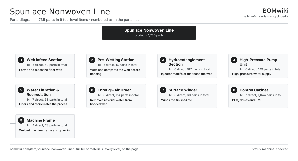
| # | Part | Qty | What it does |
|---|---|---|---|
| 1 | Web Infeed Section 5 parts | 1× | Forms and feeds the fiber web |
| 2 | Pre-Wetting Station 5 parts | 1× | Wets and compacts the web before bonding |
| 3 | Hydroentanglement Section 6 parts | 1× | Injector manifolds that bond the web |
| 4 | High-Pressure Pump Unit 6 parts | 1× | High-pressure water supply |
| 5 | Water Filtration & Recirculation 7 parts | 1× | Filters and recirculates the process water |
| 6 | Through-Air Dryer 6 parts | 1× | Removes residual water from bonded web |
| 7 | Surface Winder 6 parts | 1× | Winds the finished roll |
| 8 | Control Cabinet 7 parts | 1× | PLC, drives and HMI |
| 9 | Machine Frame 4 parts | 1× | Welded machine frame and guarding |
3D model
No 3D model yet. Have a CAD file of this? Add a 3D model. STL renders right on this page; STEP, FreeCAD, and OpenSCAD sources are welcome too (openly licensed, like all 3D models on BOMwiki).
Build & assembly graph
expand / collapse · shared sub-assemblies converge · links to related products · est. labourTap an assembly to expand/collapse · tap a part to open it · use “Open page” for any node · drag to pan, scroll to zoom.
Bill of materials for Spunlace Nonwoven Line
9 top-level lines · 139 rows shown · 1,735 parts total · indented to 3 levels| # | Item / sub-assembly | Part no. | Qty/assy | Ext. qty | Parts | Type |
|---|---|---|---|---|---|---|
| 1 | Web Infeed Section 5 parts | spunlace-nonwoven-line-web-infeed | 1× | 1 | 69 | assembly |
| 1.1 | Feed Conveyor 5 parts | spunlace-nonwoven-line-feed-conveyor | 1× | 1 | 14 | assembly |
| 1.1.1 | Conveyor Belt | spunlace-nonwoven-line-conveyor-belt | 1× | 1 | · | part |
| 1.1.2 | Drive Roller | spunlace-nonwoven-line-drive-roller | 1× | 1 | · | part |
| 1.1.3 | Idler Roller | spunlace-nonwoven-line-idler-roller | 3× | 3 | · | part |
| 1.1.4 | Ball Bearing | ball-bearing | 8× | 8 | · | part |
| 1.1.5 | Drive Belt | drive-belt | 1× | 1 | · | part |
| 1.2 | Web Spreader | spunlace-nonwoven-line-web-spreader | 1× | 1 | · | part |
| 1.3 | Edge Guide | spunlace-nonwoven-line-edge-guide | 2× | 2 | · | part |
| 1.4 | Infeed Roller | spunlace-nonwoven-line-infeed-roller | 4× | 4 | · | part |
| 1.5 | Servo Motor 4 parts | servo-motor | 2× | 2 | 24 | assembly |
| 1.5.1 | Stator Assembly 3 parts + deeper › | stator-assembly | 1× | 2 | 3 | assembly |
| 1.5.2 | Rotor Assembly 4 parts + deeper › | rotor-assembly | 1× | 2 | 19 | assembly |
| 1.5.3 | Encoder | encoder | 1× | 2 | · | part |
| 1.5.4 | Motor Housing | motor-housing | 1× | 2 | · | part |
| 2 | Pre-Wetting Station 5 parts | spunlace-nonwoven-line-prewet-station | 1× | 1 | 16 | assembly |
| 2.1 | Pre-Wet Manifold 4 parts | spunlace-nonwoven-line-prewet-manifold | 1× | 1 | 5 | assembly |
| 2.1.1 | Manifold Body | spunlace-nonwoven-line-manifold-body | 1× | 1 | · | part |
| 2.1.2 | Jet Strip | spunlace-nonwoven-line-jet-strip | 1× | 1 | · | part |
| 2.1.3 | O-Ring Set | oring-set | 2× | 2 | · | part |
| 2.1.4 | Fastener Set | fastener-set | 1× | 1 | · | part |
| 2.2 | Pre-Wet Drum | spunlace-nonwoven-line-prewet-drum | 1× | 1 | · | part |
| 2.3 | Vacuum Box 3 parts | spunlace-nonwoven-line-vacuum-box | 2× | 2 | 3 | assembly |
| 2.3.1 | Vacuum Slot | spunlace-nonwoven-line-vacuum-slot | 1× | 2 | · | part |
| 2.3.2 | Air-Water Separator | spunlace-nonwoven-line-separator-tank | 1× | 2 | · | part |
| 2.3.3 | O-Ring Set | oring-set | 1× | 2 | · | part |
| 2.4 | Spray Bar | spunlace-nonwoven-line-spray-bar | 2× | 2 | · | part |
| 2.5 | Pressure Sensor | pressure-sensor | 2× | 2 | · | part |
| 3 | Hydroentanglement Section 6 parts | spunlace-nonwoven-line-entangling-section | 1× | 1 | 187 | assembly |
| 3.1 | Injector Manifold 6 parts | spunlace-nonwoven-line-injector-manifold | 6× | 6 | 12 | assembly |
| 3.1.1 | Manifold Body | spunlace-nonwoven-line-manifold-body | 1× | 6 | · | part |
| 3.1.2 | Jet Strip | spunlace-nonwoven-line-jet-strip | 2× | 12 | · | part |
| 3.1.3 | Strip Cassette | spunlace-nonwoven-line-strip-cassette | 1× | 6 | · | part |
| 3.1.4 | High-Pressure Seal | spunlace-nonwoven-line-hp-seal | 4× | 24 | · | part |
| 3.1.5 | O-Ring Set | oring-set | 3× | 18 | · | part |
| 3.1.6 | Fastener Set | fastener-set | 1× | 6 | · | part |
| 3.2 | Support Drum 4 parts | spunlace-nonwoven-line-support-drum | 3× | 3 | 6 | assembly |
| 3.2.1 | Drum Shell | spunlace-nonwoven-line-drum-shell | 1× | 3 | · | part |
| 3.2.2 | Drum Sleeve | spunlace-nonwoven-line-drum-sleeve | 1× | 3 | · | part |
| 3.2.3 | Ball Bearing | ball-bearing | 2× | 6 | · | part |
| 3.2.4 | Oil Seal | oil-seal | 2× | 6 | · | part |
| 3.3 | Vacuum Box 3 parts | spunlace-nonwoven-line-vacuum-box | 6× | 6 | 3 | assembly |
| 3.3.1 | Vacuum Slot | spunlace-nonwoven-line-vacuum-slot | 1× | 6 | · | part |
| 3.3.2 | Air-Water Separator | spunlace-nonwoven-line-separator-tank | 1× | 6 | · | part |
| 3.3.3 | O-Ring Set | oring-set | 1× | 6 | · | part |
| 3.4 | Mesh Belt | spunlace-nonwoven-line-mesh-belt | 1× | 1 | · | part |
| 3.5 | Servo Motor 4 parts | servo-motor | 3× | 3 | 24 | assembly |
| 3.5.1 | Stator Assembly 3 parts + deeper › | stator-assembly | 1× | 3 | 3 | assembly |
| 3.5.2 | Rotor Assembly 4 parts + deeper › | rotor-assembly | 1× | 3 | 19 | assembly |
| 3.5.3 | Encoder | encoder | 1× | 3 | · | part |
| 3.5.4 | Motor Housing | motor-housing | 1× | 3 | · | part |
| 3.6 | Pressure Sensor | pressure-sensor | 6× | 6 | · | part |
| 4 | High-Pressure Pump Unit 6 parts | spunlace-nonwoven-line-pump-unit | 1× | 1 | 149 | assembly |
| 4.1 | Triplex Plunger Pump 6 parts | spunlace-nonwoven-line-hp-pump | 3× | 3 | 21 | assembly |
| 4.1.1 | Pump Crankcase | spunlace-nonwoven-line-pump-crankcase | 1× | 3 | · | part |
| 4.1.2 | Ceramic Plunger | spunlace-nonwoven-line-plunger | 3× | 9 | · | part |
| 4.1.3 | Pump Valve | spunlace-nonwoven-line-pump-valve | 6× | 18 | · | part |
| 4.1.4 | High-Pressure Seal | spunlace-nonwoven-line-hp-seal | 6× | 18 | · | part |
| 4.1.5 | Ball Bearing | ball-bearing | 2× | 6 | · | part |
| 4.1.6 | Oil Seal | oil-seal | 3× | 9 | · | part |
| 4.2 | Pump Motor 4 parts | spunlace-nonwoven-line-pump-motor | 3× | 3 | 25 | assembly |
| 4.2.1 | Stator Assembly 3 parts + deeper › | stator-assembly | 1× | 3 | 3 | assembly |
| 4.2.2 | Rotor Assembly 4 parts + deeper › | rotor-assembly | 1× | 3 | 19 | assembly |
| 4.2.3 | Ball Bearing | ball-bearing | 2× | 6 | · | part |
| 4.2.4 | Motor Frame | spunlace-nonwoven-line-motor-frame | 1× | 3 | · | part |
| 4.3 | Pressure Header | spunlace-nonwoven-line-pressure-header | 1× | 1 | · | part |
| 4.4 | Pulsation Damper | spunlace-nonwoven-line-pulsation-damper | 3× | 3 | · | part |
| 4.5 | Relief Valve | spunlace-nonwoven-line-relief-valve | 3× | 3 | · | part |
| 4.6 | Pressure Sensor | pressure-sensor | 4× | 4 | · | part |
| 5 | Water Filtration & Recirculation 7 parts | spunlace-nonwoven-line-water-system | 1× | 1 | 68 | assembly |
| 5.1 | Collection Tank | spunlace-nonwoven-line-collection-tank | 1× | 1 | · | part |
| 5.2 | Sand Filter 3 parts | spunlace-nonwoven-line-sand-filter | 2× | 2 | 3 | assembly |
| 5.2.1 | Filter Vessel | spunlace-nonwoven-line-filter-vessel | 1× | 2 | · | part |
| 5.2.2 | Filter Media | spunlace-nonwoven-line-filter-media | 1× | 2 | · | part |
| 5.2.3 | Backwash Valve | spunlace-nonwoven-line-backwash-valve | 1× | 2 | · | part |
| 5.3 | Bag Filter | spunlace-nonwoven-line-bag-filter | 4× | 4 | · | part |
| 5.4 | Transfer Pump 5 parts | spunlace-nonwoven-line-transfer-pump | 2× | 2 | 26 | assembly |
| 5.4.1 | Stator Assembly 3 parts + deeper › | stator-assembly | 1× | 2 | 3 | assembly |
| 5.4.2 | Rotor Assembly 4 parts + deeper › | rotor-assembly | 1× | 2 | 19 | assembly |
| 5.4.3 | Impeller | spunlace-nonwoven-line-impeller | 1× | 2 | · | part |
| 5.4.4 | Ball Bearing | ball-bearing | 2× | 4 | · | part |
| 5.4.5 | Oil Seal | oil-seal | 1× | 2 | · | part |
| 5.5 | Heat Exchanger | spunlace-nonwoven-line-heat-exchanger | 1× | 1 | · | part |
| 5.6 | Process Piping Set | spunlace-nonwoven-line-piping-set | 1× | 1 | · | part |
| 5.7 | Pressure Sensor | pressure-sensor | 3× | 3 | · | part |
| 6 | Through-Air Dryer 6 parts | spunlace-nonwoven-line-dryer | 1× | 1 | 114 | assembly |
| 6.1 | Dryer Drum 3 parts | spunlace-nonwoven-line-dryer-drum | 2× | 2 | 5 | assembly |
| 6.1.1 | Honeycomb Shell | spunlace-nonwoven-line-honeycomb-shell | 1× | 2 | · | part |
| 6.1.2 | Ball Bearing | ball-bearing | 2× | 4 | · | part |
| 6.1.3 | Oil Seal | oil-seal | 2× | 4 | · | part |
| 6.2 | Dryer Circulation Fan 4 parts | spunlace-nonwoven-line-dryer-fan | 2× | 2 | 25 | assembly |
| 6.2.1 | Stator Assembly 3 parts + deeper › | stator-assembly | 1× | 2 | 3 | assembly |
| 6.2.2 | Rotor Assembly 4 parts + deeper › | rotor-assembly | 1× | 2 | 19 | assembly |
| 6.2.3 | Fan Impeller | spunlace-nonwoven-line-fan-impeller | 1× | 2 | · | part |
| 6.2.4 | Ball Bearing | ball-bearing | 2× | 4 | · | part |
| 6.3 | Gas Burner Module | spunlace-nonwoven-line-burner-module | 1× | 1 | · | part |
| 6.4 | Heating Element | heating-element | 4× | 4 | · | part |
| 6.5 | Dryer Hood | spunlace-nonwoven-line-dryer-hood | 1× | 1 | · | part |
| 6.6 | Servo Motor 4 parts | servo-motor | 2× | 2 | 24 | assembly |
| 6.6.1 | Stator Assembly 3 parts + deeper › | stator-assembly | 1× | 2 | 3 | assembly |
| 6.6.2 | Rotor Assembly 4 parts + deeper › | rotor-assembly | 1× | 2 | 19 | assembly |
| 6.6.3 | Encoder | encoder | 1× | 2 | · | part |
| 6.6.4 | Motor Housing | motor-housing | 1× | 2 | · | part |
| 7 | Surface Winder 6 parts | spunlace-nonwoven-line-winder | 1× | 1 | 60 | assembly |
| 7.1 | Winding Roller | spunlace-nonwoven-line-winding-roller | 2× | 2 | · | part |
| 7.2 | Slitter Set | spunlace-nonwoven-line-slitter-set | 1× | 1 | · | part |
| 7.3 | Dancer Roller | spunlace-nonwoven-line-dancer-roller | 1× | 1 | · | part |
| 7.4 | Core Chuck | spunlace-nonwoven-line-core-chuck | 2× | 2 | · | part |
| 7.5 | Servo Motor 4 parts | servo-motor | 2× | 2 | 24 | assembly |
| 7.5.1 | Stator Assembly 3 parts + deeper › | stator-assembly | 1× | 2 | 3 | assembly |
| 7.5.2 | Rotor Assembly 4 parts + deeper › | rotor-assembly | 1× | 2 | 19 | assembly |
| 7.5.3 | Encoder | encoder | 1× | 2 | · | part |
| 7.5.4 | Motor Housing | motor-housing | 1× | 2 | · | part |
| 7.6 | Ball Bearing | ball-bearing | 6× | 6 | · | part |
| 8 | Control Cabinet 7 parts | spunlace-nonwoven-line-control-cabinet | 1× | 1 | 1,044 | assembly |
| 8.1 | PLC Module 4 parts | spunlace-nonwoven-line-plc | 1× | 1 | 215 | assembly |
| 8.1.1 | Bare PCB | pcb-bare | 1× | 1 | · | part |
| 8.1.2 | Microcontroller | mcu | 2× | 2 | · | part |
| 8.1.3 | SMD Passive (R/C/L) | smd-passives | 200× | 200 | · | part |
| 8.1.4 | Connector | connector | 12× | 12 | · | part |
| 8.2 | Variable Frequency Drive 4 parts | spunlace-nonwoven-line-vfd | 6× | 6 | 123 | assembly |
| 8.2.1 | Bare PCB | pcb-bare | 1× | 6 | · | part |
| 8.2.2 | Microcontroller | mcu | 1× | 6 | · | part |
| 8.2.3 | SMD Passive (R/C/L) | smd-passives | 120× | 720 | · | part |
| 8.2.4 | Drive Heatsink | spunlace-nonwoven-line-drive-heatsink | 1× | 6 | · | part |
| 8.3 | Operator HMI 4 parts | spunlace-nonwoven-line-hmi | 1× | 1 | 4 | assembly |
| 8.3.1 | LCD Panel | lcd-panel | 1× | 1 | · | part |
| 8.3.2 | Touch Digitizer | touch-digitizer | 1× | 1 | · | part |
| 8.3.3 | Compute SoC Module | soc-module | 1× | 1 | · | part |
| 8.3.4 | Bare PCB | pcb-bare | 1× | 1 | · | part |
| 8.4 | Power Supply | power-supply | 2× | 2 | · | part |
| 8.5 | Relay | relay | 24× | 24 | · | part |
| 8.6 | Wire Bundle | wire-bundle | 1× | 1 | · | part |
| 8.7 | Connector | connector | 60× | 60 | · | part |
| 9 | Machine Frame 4 parts | spunlace-nonwoven-line-frame | 1× | 1 | 28 | assembly |
| 9.1 | Frame Weldment | spunlace-nonwoven-line-frame-weldment | 1× | 1 | · | part |
| 9.2 | Sheet Metal Panel | sheet-panel | 24× | 24 | · | part |
| 9.3 | Walkway & Platform | spunlace-nonwoven-line-walkway | 2× | 2 | · | part |
| 9.4 | Fastener Set | fastener-set | 1× | 1 | · | part |
Related products
same domain, ranked by shared parts Textile Stenter Frame
1,683 parts · shares 9 with this page
Textile Stenter Frame
1,683 parts · shares 9 with this page
 Automatic Fabric Cutting Machine
1,695 parts · shares 9 with this page
Automatic Fabric Cutting Machine
1,695 parts · shares 9 with this page
Sourcing: possible vendors
Browse the supplier directory → Prices, MOQ, and lead times are algorithmic estimates, not quotes, and not claims about these companies. Company mappings are curated by keyword; est. price band $10k–$1M. How estimates work| Vendor | HQ | Specialty | MOQ | Lead time |
|---|---|---|---|---|
|
🇨🇭Rieter
rieter.com ↗
|
Winterthur, CH | Spinning machinery | 10 units | 14–24 wks |
| truetzschler.com ↗ | Mönchengladbach, DE | Textile machinery | 10 units | 14–24 wks |
|
🇧🇪Picanol
picanol.be ↗
|
Ypres, BE | Weaving machines | 10 units | 14–24 wks |
| karlmayer.com ↗ | Obertshausen, DE | Warp knitting machines | 10 units | 14–24 wks |
|
🇨🇭Saurer
saurer.com ↗
|
Arbon, CH | Spinning & embroidery | 10 units | 14–24 wks |
1,044-word article