Textile Combing Machine
ProductOverview
A combing machine removes the short fibers from cotton so the mill can spin fine, smooth, strong yarn. Carding cleans and aligns the fiber but leaves the full range of fiber lengths in the sliver, including short fibers that add no strength and make the yarn hairy and weak. Combing pulls those short fibers out, along with any neps and trash the card missed, and leaves only the longer fibers laid parallel. The waste it takes out is called noil, and a mill can comb out anywhere from eight to twenty-two percent of the feed depending on how fine and clean the target yarn is.
Combed yarn is the basis of high-count shirting, fine knitwear and sewing thread. The process costs fiber and adds a machine to the line, so coarse yarns are spun carded, without combing. The machine works in a repeating cycle rather than continuously: it grips a tuft, combs it, draws it off and joins it to the last, hundreds of times a minute across eight heads working in parallel.
Feeding the lap
The comber does not feed from sliver. Ahead of it a lap former winds several drawn slivers into a flat compact sheet called a lap, and the Lap Feed & Creel station holds these laps and unrolls each one into its combing head. A Feed Roller pushes a small measured length of lap forward before each combing stroke, and a Feed Advance Pawl ratchet sets exactly how much, which is one of the levers on combing quality: a shorter feed combs each length more thoroughly and takes more noil.
The combing cycle
The work happens in the Combing Head, and the sequence is the heart of the machine. First the Nipper Plate Assembly clamps the fed lap firmly by its rear, leaving a fringe of fiber hanging free in front of the jaw. Then the Circular Comb Cylinder, a rotating cylinder carrying a Comb Needle Segment of graded needles, sweeps through that hanging fringe. Because the fiber is held at the root, the comb can only drag out fibers shorter than the held length, plus any loose trash and neps, while the long fibers stay anchored. That extracted material is the noil.
The nipper then opens and the cleaned fringe is presented forward. As it is drawn off, the Top Comb drops into the fiber and cleans the leading end too, catching short fibers and trash that the circular comb at the root could not reach. So each tuft is combed from both ends across the cycle.
Detaching and piecing
Because the lap is fed and combed in steps, the combed fiber comes off in separate tufts, not a continuous strand. The Detaching & Piecing rollers turn this back into a continuous web. They draw each freshly combed tuft forward and, timed by the Detaching Motion Cam, lay it overlapping the tail of the previous tuft on the Piecing Support Plate. The overlap, called the piecing, hides the join so the web has no thin spot where one tuft meets the next. Getting the piecing even is what separates a good comber setting from a bad one, since a regular piecing fault shows up as periodic unevenness in the yarn.
Forming the sliver
The eight heads each deliver a thin combed web, and these run forward on the Web Table & Draft, where they are gathered side by side, drafted a final time and drawn together through a trumpet into a single round sliver. Calender rollers compact it and the Sliver Coiler lays it into a can in even coils, the same end stage a draw frame uses, ready for the next drawing passage or the roving frame.
Noil removal
Removing the noil cleanly is essential, since it is the whole purpose of the machine. The Noil Suction System system pulls the combed-out short fibers off the circular comb each stroke, with a Comb Cleaning Brush brush wiping the needles clear so they keep combing. The noil from all heads collects in a box, and its weight against the lap fed gives the comb percentage, a number the mill controls tightly because it sets both the yarn quality and the fiber loss.
Drive, materials and use
The nipper, feed and detaching motions are all driven from a Main Camshaft so they stay in fixed phase, while servo drives handle the table draft and coiler. The Machine Control sets comb speed, feed and noil level and logs comb percentage and production. The base and head castings are cast iron to absorb the impact of the nipper striking hundreds of times a minute. The comb needles are hardened steel, replaced as a segment when they dull. Combing sits between the lap former and the finisher draw frame in the comber line, and it is the step that defines whether a mill can sell into the combed-yarn market at all.
Textile Combing Machine parts and their functions
10 top-level parts · 304 parts in total · full bill of materials below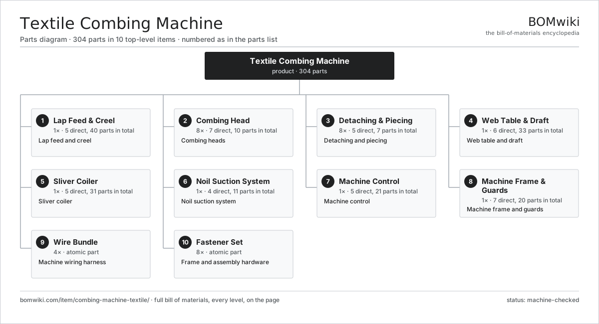
| # | Part | Qty | What it does |
|---|---|---|---|
| 1 | Lap Feed & Creel 5 parts | 1× | Lap feed and creel |
| 2 | Combing Head 7 parts | 8× | Combing heads |
| 3 | Detaching & Piecing 5 parts | 8× | Detaching and piecing |
| 4 | Web Table & Draft 6 parts | 1× | Web table and draft |
| 5 | Sliver Coiler 5 parts | 1× | Sliver coiler |
| 6 | Noil Suction System 4 parts | 1× | Noil suction system |
| 7 | Machine Control 5 parts | 1× | Machine control |
| 8 | Machine Frame & Guards 7 parts | 1× | Machine frame and guards |
| 9 | Wire Bundle | 4× | Machine wiring harness |
| 10 | Fastener Set | 8× | Frame and assembly hardware |
3D model
No 3D model yet. Have a CAD file of this? Add a 3D model. STL renders right on this page; STEP, FreeCAD, and OpenSCAD sources are welcome too (openly licensed, like all 3D models on BOMwiki).
Build & assembly graph
expand / collapse · shared sub-assemblies converge · links to related products · est. labourTap an assembly to expand/collapse · tap a part to open it · use “Open page” for any node · drag to pan, scroll to zoom.
Bill of materials for Textile Combing Machine
10 top-level lines · 66 rows shown · 304 parts total · indented to 3 levels| # | Item / sub-assembly | Part no. | Qty/assy | Ext. qty | Parts | Type |
|---|---|---|---|---|---|---|
| 1 | Lap Feed & Creel 5 parts | combing-machine-textile-lap-feed | 1× | 1 | 40 | assembly |
| 1.1 | Lap Unwind Roller | combing-machine-textile-lap-roller | 8× | 8 | · | part |
| 1.2 | Feed Roller | combing-machine-textile-feed-roller | 8× | 8 | · | part |
| 1.3 | Feed Advance Pawl | combing-machine-textile-feed-pawl | 8× | 8 | · | part |
| 1.4 | Lap Spindle | combing-machine-textile-lap-spindle | 8× | 8 | · | part |
| 1.5 | Ball Bearing | ball-bearing | 8× | 8 | · | part |
| 2 | Combing Head 7 parts | combing-machine-textile-comb-head | 8× | 8 | 10 | assembly |
| 2.1 | Nipper Plate Assembly | combing-machine-textile-nipper | 1× | 8 | · | part |
| 2.2 | Circular Comb Cylinder | combing-machine-textile-circular-comb | 1× | 8 | · | part |
| 2.3 | Top Comb | combing-machine-textile-top-comb | 1× | 8 | · | part |
| 2.4 | Comb Needle Segment | combing-machine-textile-comb-segment | 1× | 8 | · | part |
| 2.5 | Cushion Plate | combing-machine-textile-cushion-plate | 1× | 8 | · | part |
| 2.6 | Comb Cylinder Shaft | combing-machine-textile-comb-shaft | 1× | 8 | · | part |
| 2.7 | Ball Bearing | ball-bearing | 4× | 32 | · | part |
| 3 | Detaching & Piecing 5 parts | combing-machine-textile-detaching | 8× | 8 | 7 | assembly |
| 3.1 | Detaching Roller | combing-machine-textile-detaching-roller | 2× | 16 | · | part |
| 3.2 | Detaching Motion Cam | combing-machine-textile-detaching-cam | 1× | 8 | · | part |
| 3.3 | Piecing Support Plate | combing-machine-textile-piecing-plate | 1× | 8 | · | part |
| 3.4 | Indexing Gear | combing-machine-textile-index-gear | 1× | 8 | · | part |
| 3.5 | Helical Gear Pair | gear-pair | 2× | 16 | · | part |
| 4 | Web Table & Draft 6 parts | combing-machine-textile-web-table | 1× | 1 | 33 | assembly |
| 4.1 | Web Guide Plate | combing-machine-textile-web-plate | 1× | 1 | · | part |
| 4.2 | Table Drafting Unit | combing-machine-textile-table-draft | 1× | 1 | · | part |
| 4.3 | Web Condensing Trumpet | combing-machine-textile-web-trumpet | 1× | 1 | · | part |
| 4.4 | Calender Roller | combing-machine-textile-calender-roller | 2× | 2 | · | part |
| 4.5 | Servo Motor 4 parts | servo-motor | 1× | 1 | 24 | assembly |
| 4.5.1 | Stator Assembly 3 parts + deeper › | stator-assembly | 1× | 1 | 3 | assembly |
| 4.5.2 | Rotor Assembly 4 parts + deeper › | rotor-assembly | 1× | 1 | 19 | assembly |
| 4.5.3 | Encoder | encoder | 1× | 1 | · | part |
| 4.5.4 | Motor Housing | motor-housing | 1× | 1 | · | part |
| 4.6 | Ball Bearing | ball-bearing | 4× | 4 | · | part |
| 5 | Sliver Coiler 5 parts | combing-machine-textile-coiler | 1× | 1 | 31 | assembly |
| 5.1 | Coiler Tube | combing-machine-textile-coiler-tube | 1× | 1 | · | part |
| 5.2 | Coiler Plate | combing-machine-textile-coiler-plate | 1× | 1 | · | part |
| 5.3 | Can Turntable | combing-machine-textile-can-turntable | 1× | 1 | · | part |
| 5.4 | Servo Motor 4 parts | servo-motor | 1× | 1 | 24 | assembly |
| 5.4.1 | Stator Assembly 3 parts + deeper › | stator-assembly | 1× | 1 | 3 | assembly |
| 5.4.2 | Rotor Assembly 4 parts + deeper › | rotor-assembly | 1× | 1 | 19 | assembly |
| 5.4.3 | Encoder | encoder | 1× | 1 | · | part |
| 5.4.4 | Motor Housing | motor-housing | 1× | 1 | · | part |
| 5.5 | Ball Bearing | ball-bearing | 4× | 4 | · | part |
| 6 | Noil Suction System 4 parts | combing-machine-textile-noil-suction | 1× | 1 | 11 | assembly |
| 6.1 | Noil Suction Fan | combing-machine-textile-noil-fan | 1× | 1 | · | part |
| 6.2 | Noil Ducting | combing-machine-textile-noil-duct | 1× | 1 | · | part |
| 6.3 | Noil Collection Box | combing-machine-textile-noil-box | 1× | 1 | · | part |
| 6.4 | Comb Cleaning Brush | combing-machine-textile-comb-cleaner | 8× | 8 | · | part |
| 7 | Machine Control 5 parts | combing-machine-textile-control | 1× | 1 | 21 | assembly |
| 7.1 | Main Controller 4 parts | combing-machine-textile-controller | 1× | 1 | 7 | assembly |
| 7.1.1 | Bare PCB | pcb-bare | 1× | 1 | · | part |
| 7.1.2 | Microcontroller | mcu | 1× | 1 | · | part |
| 7.1.3 | SMD Passive (R/C/L) | smd-passives | 1× | 1 | · | part |
| 7.1.4 | Connector | connector | 4× | 4 | · | part |
| 7.2 | LCD Panel | lcd-panel | 1× | 1 | · | part |
| 7.3 | Power Supply | power-supply | 1× | 1 | · | part |
| 7.4 | Relay | relay | 4× | 4 | · | part |
| 7.5 | Connector | connector | 8× | 8 | · | part |
| 8 | Machine Frame & Guards 7 parts | combing-machine-textile-frame | 1× | 1 | 20 | assembly |
| 8.1 | Cast Base | combing-machine-textile-base | 1× | 1 | · | part |
| 8.2 | Main Camshaft | combing-machine-textile-camshaft | 1× | 1 | · | part |
| 8.3 | Comb Head Guard | combing-machine-textile-guard | 6× | 6 | · | part |
| 8.4 | Gearbox Housing | gearbox-housing | 1× | 1 | · | part |
| 8.5 | Helical Gear Pair | gear-pair | 4× | 4 | · | part |
| 8.6 | Sheet Metal Panel | sheet-panel | 6× | 6 | · | part |
| 8.7 | Drive Belt | drive-belt | 1× | 1 | · | part |
| 9 | Wire Bundle | wire-bundle | 4× | 4 | · | part |
| 10 | Fastener Set | fastener-set | 8× | 8 | · | part |
Related products
same domain, ranked by shared parts Automatic Fabric Cutting Machine
1,695 parts · shares 5 with this page
Automatic Winding Machine
288 parts · shares 5 with this page
Fabric Coating Machine
316 parts · shares 5 with this page
FDY Filament Spinning Line
679 parts · shares 5 with this page
Automatic Fabric Cutting Machine
1,695 parts · shares 5 with this page
Automatic Winding Machine
288 parts · shares 5 with this page
Fabric Coating Machine
316 parts · shares 5 with this page
FDY Filament Spinning Line
679 parts · shares 5 with this page
 Industrial Quilting Machine
1,090 parts · shares 5 with this page
Industrial Quilting Machine
1,090 parts · shares 5 with this page
Sourcing: possible vendors
Browse the supplier directory → Prices, MOQ, and lead times are algorithmic estimates, not quotes, and not claims about these companies. Company mappings are curated by keyword; est. price band $10k–$1M. How estimates work| Vendor | HQ | Specialty | MOQ | Lead time |
|---|---|---|---|---|
|
🇨🇭Rieter
rieter.com ↗
|
Winterthur, CH | Spinning machinery | 10 units | 14–24 wks |
| truetzschler.com ↗ | Mönchengladbach, DE | Textile machinery | 10 units | 14–24 wks |
|
🇧🇪Picanol
picanol.be ↗
|
Ypres, BE | Weaving machines | 10 units | 14–24 wks |
| karlmayer.com ↗ | Obertshausen, DE | Warp knitting machines | 10 units | 14–24 wks |
|
🇨🇭Saurer
saurer.com ↗
|
Arbon, CH | Spinning & embroidery | 10 units | 14–24 wks |
851-word article