Wind Farm Service Boat
ProductOverview
A wind farm service boat, known in the industry as a crew transfer vessel or CTV, is a fast aluminium catamaran that carries wind technicians and their equipment from shore or a base port out to offshore wind turbines and back. Its whole design is shaped by one demanding maneuver: pushing its bow firmly against the ladder on a turbine foundation and holding it there by engine thrust alone while technicians step across, in open sea, often in significant waves. The major systems are the Catamaran Hull, the twin Propulsion Train trains, the Bow Transfer Fender System used for transfers, the Wheelhouse, the Technician Cabin for technicians, and the Cargo Deck for spares.
Supporting these are the Electrical System system, the Safety Systems that the offshore environment demands, and the Auxiliary Systems handling fuel, water and bilge. The boat balances two conflicting needs: high speed to cross open water quickly during short weather windows, and fine, stable control to sit against a turbine without crashing into it.
Catamaran hull
The Catamaran Hull is a catamaran, two slender aluminium Demihull hulls joined by a Wet Deck (Bridge Structure) bridging structure held high above the water to clear wave slamming. Two hulls spaced apart give a wide, stable platform that rolls far less than a single hull of the same size, which matters both for technician comfort on the transit and for steadiness during transfer. Aluminium keeps the boat light and fast and resists corrosion in salt water.
The hulls are subdivided by Watertight Bulkhead walls and stiffened by Transverse Frame members, with reinforced Transfer Bow Section structures built to take the repeated thrust loads of pushing against a turbine landing. That bow reinforcement is not incidental: a CTV may make dozens of push-ons in a working day, each one a controlled collision.
Propulsion
Each Propulsion Train train pairs a high-speed Main Diesel Engine with a Waterjet Unit. The engine is a common-rail marine diesel built on an Engine Block with a Crankshaft, several Piston & Conrod units, twin Turbocharger boosting, and a Common-Rail Fuel System fuel system for clean, responsive power. It drives a Jet Reduction Gearbox and then the waterjet.
The waterjet is chosen over a propeller for good reasons offshore. Water enters through a Jet Intake Duct, a Jet Impeller accelerates it, a Stator Vane Ring ring straightens the flow, and the stream leaves through a Steering Nozzle that vectors thrust for steering, with a Reverse Bucket that deflects the jet forward for braking and astern thrust. The result is precise, instantaneous thrust control in any direction with no exposed propeller, letting the pilot hold the boat steady against a turbine and run safely in shallow water around foundations.
Transfer fender and wheelhouse
The defining feature is the Bow Transfer Fender System. A large High-Friction Bow Fender with replaceable Friction Pad faces is pressed against the turbine boat-landing, and its grip is what lets the boat hold position by thrust alone, the bow effectively clamped to the ladder by friction. Integrated Access Step steps and Transfer Handrail rails let a technician cross from the bow onto the turbine ladder.
Above, the Wheelhouse gives the pilot a clear forward view over the bow for the push-on. The Helm Console carries throttle levers and a single Manoeuvring Joystick that blends jet steering and thrust, a Navigation Suite of radar, chart plotter, AIS and VHF, and suspension Suspension Helm Seat seats to spare the crew from wave-impact shock.
Cabin and cargo
Technicians ride in the Technician Cabin, where shock-mitigating Shock-Mitigating Seat seats with belts and dampers absorb the slamming of a fast catamaran in a seaway, a heated Cabin HVAC Unit keeps the space comfortable, and racks hold their gear. The Cargo Deck aft carries spare parts and tools out to the turbines, with a Deck Crane for lifting loads up to the turbine platform, lashing points, and deck tanks for transferring fuel or fluids.
Power, safety and auxiliaries
The Electrical System system runs on a diesel Diesel Generator Set feeding a Main Switchboard, a battery bank, navigation lights and deck floodlights for night work. Because the boat operates far offshore with people moving between vessel and structure, the Safety Systems are extensive: life rafts, a Man-Overboard Recovery System with davit and scramble net, engine-room fire suppression, an EPIRB Beacon beacon, and lifejackets for everyone aboard. The Auxiliary Systems round out the boat with fuel storage and transfer, bilge pumps, fresh water, sea-chest cooling intakes and the steering hydraulics for the waterjets.
Use and operation
A CTV works to weather windows. On a suitable morning it loads technicians and gear at the base port, crosses to the wind farm at speed, then visits turbines in turn, pushing on at each so crews can transfer up, and standing by or shuttling between machines through the day before bringing everyone home. The whole vessel is optimized for that rhythm: fast enough to make use of short calm spells, stable and controllable enough to transfer people safely in the chop that remains, and rugged enough to do it day after day. As offshore wind farms have moved farther from shore, larger service operation vessels increasingly act as floating bases, but the CTV remains the workhorse that puts technicians on the turbines.
Wind Farm Service Boat parts and their functions
9 top-level parts · 797 parts in total · full bill of materials below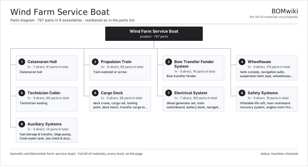
| # | Part | Qty | What it does |
|---|---|---|---|
| 1 | Catamaran Hull 7 parts | 1× | Catamaran hull |
| 2 | Propulsion Train 6 parts | 2× | Twin waterjet or screw |
| 3 | Bow Transfer Fender System 5 parts | 1× | Bow transfer fender |
| 4 | Wheelhouse 5 parts | 1× | Forward-looking helm with full visibility over the bow for the precise push-on maneuver against a turbine. |
| 5 | Technician Cabin 5 parts | 1× | Technician seating |
| 6 | Cargo Deck 5 parts | 1× | Open aft deck with a crane and lashing points for ferrying spare parts and tools out to the turbines. |
| 7 | Electrical System 7 parts | 1× | |
| 8 | Safety Systems 5 parts | 1× | |
| 9 | Auxiliary Systems 5 parts | 1× |
3D model
No 3D model yet. Have a CAD file of this? Add a 3D model — STL renders right on this page; STEP, FreeCAD, and OpenSCAD sources are welcome too (openly licensed, like all 3D models on BOMwiki).
Build & assembly graph
expand / collapse · shared sub-assemblies converge · links to related products · est. labourTap an assembly to expand/collapse · tap a part to open it · use “Open page” for any node · drag to pan, scroll to zoom.
Bill of materials for Wind Farm Service Boat
9 top-level lines · 117 rows shown · 797 parts total · indented to 3 levels| # | Item / sub-assembly | Part no. | Qty/assy | Ext. qty | Parts | Type |
|---|---|---|---|---|---|---|
| 1 | Catamaran Hull 7 parts | wfsb-hull | 1× | 1 | 81 | assembly |
| 1.1 | Demihull | wfsb-demihull | 2× | 2 | · | part |
| 1.2 | Wet Deck (Bridge Structure) | wfsb-wet-deck | 1× | 1 | · | part |
| 1.3 | Watertight Bulkhead | wfsb-bulkhead | 8× | 8 | · | part |
| 1.4 | Transverse Frame | wfsb-frame | 30× | 30 | · | part |
| 1.5 | Keel Bar | wfsb-keel-bar | 2× | 2 | · | part |
| 1.6 | Transfer Bow Section | wfsb-bow-section | 2× | 2 | · | part |
| 1.7 | Sheet Metal Panel | sheet-panel | 36× | 36 | · | part |
| 2 | Propulsion Train 6 parts | wfsb-propulsion | 2× | 2 | 89 | assembly |
| 2.1 | Main Diesel Engine 7 parts | wfsb-main-engine | 1× | 2 | 66 | assembly |
| 2.1.1 | Engine Block | wfsb-engine-block | 1× | 2 | · | part |
| 2.1.2 | Crankshaft | wfsb-crankshaft | 1× | 2 | · | part |
| 2.1.3 | Piston & Conrod 4 parts + deeper › | wfsb-piston-assembly | 8× | 16 | 6 | assembly |
| 2.1.4 | Cylinder Head | wfsb-cylinder-head | 2× | 4 | · | part |
| 2.1.5 | Turbocharger | wfsb-turbocharger | 2× | 4 | · | part |
| 2.1.6 | Common-Rail Fuel System 3 parts + deeper › | wfsb-common-rail | 1× | 2 | 11 | assembly |
| 2.1.7 | Engine Heat Exchanger | wfsb-engine-cooler | 1× | 2 | · | part |
| 2.2 | Jet Reduction Gearbox 4 parts | wfsb-jet-gearbox | 1× | 2 | 8 | assembly |
| 2.2.1 | Helical Gear Pair | gear-pair | 1× | 2 | · | part |
| 2.2.2 | Gearbox Housing | gearbox-housing | 1× | 2 | · | part |
| 2.2.3 | Ball Bearing | ball-bearing | 4× | 8 | · | part |
| 2.2.4 | Oil Seal | oil-seal | 2× | 4 | · | part |
| 2.3 | Waterjet Unit 7 parts | wfsb-waterjet | 1× | 2 | 9 | assembly |
| 2.3.1 | Jet Impeller | wfsb-jet-impeller | 1× | 2 | · | part |
| 2.3.2 | Jet Shaft | wfsb-jet-shaft | 1× | 2 | · | part |
| 2.3.3 | Stator Vane Ring | wfsb-stator-vane | 1× | 2 | · | part |
| 2.3.4 | Steering Nozzle | wfsb-steering-nozzle | 1× | 2 | · | part |
| 2.3.5 | Reverse Bucket | wfsb-reverse-bucket | 1× | 2 | · | part |
| 2.3.6 | Ball Bearing | ball-bearing | 2× | 4 | · | part |
| 2.3.7 | Oil Seal | oil-seal | 2× | 4 | · | part |
| 2.4 | Jet Intake Duct | wfsb-jet-intake | 1× | 2 | · | part |
| 2.5 | Jet Control Actuator | wfsb-control-actuator | 1× | 2 | · | part |
| 2.6 | Ball Bearing | ball-bearing | 4× | 8 | · | part |
| 3 | Bow Transfer Fender System 5 parts | wfsb-fender-system | 1× | 1 | 16 | assembly |
| 3.1 | High-Friction Bow Fender | wfsb-bow-fender | 1× | 1 | · | part |
| 3.2 | Fender Mounting Frame | wfsb-fender-mount | 1× | 1 | · | part |
| 3.3 | Access Step | wfsb-access-step | 4× | 4 | · | part |
| 3.4 | Transfer Handrail | wfsb-handrail | 2× | 2 | · | part |
| 3.5 | Friction Pad | wfsb-friction-pad | 8× | 8 | · | part |
| 4 | Wheelhouse 5 parts | wfsb-wheelhouse | 1× | 1 | 215 | assembly |
| 4.1 | Helm Console 6 parts | wfsb-helm-console | 1× | 1 | 189 | assembly |
| 4.1.1 | Bare PCB | pcb-bare | 2× | 2 | · | part |
| 4.1.2 | Microcontroller | mcu | 2× | 2 | · | part |
| 4.1.3 | LCD Panel | lcd-panel | 2× | 2 | · | part |
| 4.1.4 | Throttle Lever | wfsb-throttle-lever | 2× | 2 | · | part |
| 4.1.5 | Manoeuvring Joystick | wfsb-joystick | 1× | 1 | · | part |
| 4.1.6 | SMD Passive (R/C/L) | smd-passives | 180× | 180 | · | part |
| 4.2 | Navigation Suite 5 parts | wfsb-navigation-suite | 1× | 1 | 6 | assembly |
| 4.2.1 | Radar Scanner | wfsb-radar | 1× | 1 | · | part |
| 4.2.2 | GPS Chart Plotter | wfsb-gps-plotter | 1× | 1 | · | part |
| 4.2.3 | VHF Radio | wfsb-vhf-radio | 2× | 2 | · | part |
| 4.2.4 | AIS Transponder | wfsb-ais | 1× | 1 | · | part |
| 4.2.5 | Depth Sounder | wfsb-depth-sounder | 1× | 1 | · | part |
| 4.3 | Suspension Helm Seat 3 parts | wfsb-helm-seat | 2× | 2 | 4 | assembly |
| 4.3.1 | Seat Frame | wfsb-seat-frame | 1× | 2 | · | part |
| 4.3.2 | Coil Spring | coil-spring | 2× | 4 | · | part |
| 4.3.3 | Seat Cushion | wfsb-seat-cushion | 1× | 2 | · | part |
| 4.4 | Wheelhouse Window | wfsb-window | 8× | 8 | · | part |
| 4.5 | Window Wiper | wfsb-wiper | 4× | 4 | · | part |
| 5 | Technician Cabin 5 parts | wfsb-cabin | 1× | 1 | 86 | assembly |
| 5.1 | Shock-Mitigating Seat 5 parts | wfsb-shock-seat | 12× | 12 | 6 | assembly |
| 5.1.1 | Seat Frame | wfsb-seat-frame | 1× | 12 | · | part |
| 5.1.2 | Coil Spring | coil-spring | 2× | 24 | · | part |
| 5.1.3 | Seat Damper | wfsb-seat-damper | 1× | 12 | · | part |
| 5.1.4 | Seat Cushion | wfsb-seat-cushion | 1× | 12 | · | part |
| 5.1.5 | Seatbelt | wfsb-seatbelt | 1× | 12 | · | part |
| 5.2 | Cabin HVAC Unit 3 parts | wfsb-cabin-hvac | 1× | 1 | 3 | assembly |
| 5.2.1 | Heating Element | heating-element | 1× | 1 | · | part |
| 5.2.2 | Blower Fan | wfsb-blower | 1× | 1 | · | part |
| 5.2.3 | Air Filter | wfsb-air-filter | 1× | 1 | · | part |
| 5.3 | Cabin Window | wfsb-cabin-window | 8× | 8 | · | part |
| 5.4 | Luggage Rack | wfsb-luggage-rack | 2× | 2 | · | part |
| 5.5 | Marine Toilet Module | wfsb-toilet-module | 1× | 1 | · | part |
| 6 | Cargo Deck 5 parts | wfsb-cargo-deck | 1× | 1 | 28 | assembly |
| 6.1 | Deck Crane 5 parts | wfsb-deck-crane | 1× | 1 | 8 | assembly |
| 6.1.1 | Crane Boom | wfsb-crane-boom | 1× | 1 | · | part |
| 6.1.2 | Crane Winch | wfsb-crane-winch | 1× | 1 | · | part |
| 6.1.3 | Crane Hydraulic Pack | wfsb-crane-hydraulics | 1× | 1 | · | part |
| 6.1.4 | Helical Gear Pair | gear-pair | 1× | 1 | · | part |
| 6.1.5 | Ball Bearing | ball-bearing | 4× | 4 | · | part |
| 6.2 | Cargo Rail | wfsb-cargo-rail | 4× | 4 | · | part |
| 6.3 | Lashing Point | wfsb-lashing-point | 12× | 12 | · | part |
| 6.4 | Deck Hatch | wfsb-deck-hatch | 2× | 2 | · | part |
| 6.5 | Transfer Cargo Tank | wfsb-cargo-tank | 2× | 2 | · | part |
| 7 | Electrical System 7 parts | wfsb-electrical | 1× | 1 | 160 | assembly |
| 7.1 | Diesel Generator Set 3 parts | wfsb-generator-set | 1× | 1 | 23 | assembly |
| 7.1.1 | Generator Diesel Engine | wfsb-genset-engine | 1× | 1 | · | part |
| 7.1.2 | Stator Assembly 3 parts + deeper › | stator-assembly | 1× | 1 | 3 | assembly |
| 7.1.3 | Rotor Assembly 4 parts + deeper › | rotor-assembly | 1× | 1 | 19 | assembly |
| 7.2 | Main Switchboard 4 parts | wfsb-switchboard | 1× | 1 | 93 | assembly |
| 7.2.1 | Bare PCB | pcb-bare | 1× | 1 | · | part |
| 7.2.2 | Relay | relay | 12× | 12 | · | part |
| 7.2.3 | Circuit Breaker | wfsb-breaker | 10× | 10 | · | part |
| 7.2.4 | SMD Passive (R/C/L) | smd-passives | 70× | 70 | · | part |
| 7.3 | Battery Bank | wfsb-battery-bank | 1× | 1 | · | part |
| 7.4 | Navigation Light | wfsb-nav-light | 8× | 8 | · | part |
| 7.5 | Deck Floodlight | wfsb-deck-floodlight | 4× | 4 | · | part |
| 7.6 | Wire Bundle | wire-bundle | 1× | 1 | · | part |
| 7.7 | Connector | connector | 30× | 30 | · | part |
| 8 | Safety Systems 5 parts | wfsb-safety-systems | 1× | 1 | 19 | assembly |
| 8.1 | Inflatable Life Raft | wfsb-life-raft | 2× | 2 | · | part |
| 8.2 | Man-Overboard Recovery System | wfsb-man-overboard-system | 1× | 1 | · | part |
| 8.3 | Engine Room Fire Suppression | wfsb-fire-suppression | 1× | 1 | · | part |
| 8.4 | EPIRB Beacon | wfsb-epirb | 1× | 1 | · | part |
| 8.5 | Lifejacket | wfsb-lifejacket | 14× | 14 | · | part |
| 9 | Auxiliary Systems 5 parts | wfsb-auxiliary-systems | 1× | 1 | 14 | assembly |
| 9.1 | Fuel Storage & Transfer 3 parts | wfsb-fuel-system | 1× | 1 | 4 | assembly |
| 9.1.1 | Fuel Tank | wfsb-fuel-tank | 2× | 2 | · | part |
| 9.1.2 | Fuel Transfer Pump | wfsb-fuel-transfer-pump | 1× | 1 | · | part |
| 9.1.3 | Fuel Filter | wfsb-fuel-filter | 1× | 1 | · | part |
| 9.2 | Bilge Pump | wfsb-bilge-pump | 2× | 2 | · | part |
| 9.3 | Fresh Water Tank | wfsb-fresh-water-tank | 1× | 1 | · | part |
| 9.4 | Sea Chest & Strainer | wfsb-cooling-seachest | 2× | 2 | · | part |
| 9.5 | Steering Hydraulic Pack 3 parts | wfsb-steering-hydraulics | 1× | 1 | 5 | assembly |
| 9.5.1 | Steering Hydraulic Pump | wfsb-steering-pump | 1× | 1 | · | part |
| 9.5.2 | O-Ring Set | oring-set | 3× | 3 | · | part |
| 9.5.3 | Pressure Sensor | pressure-sensor | 1× | 1 | · | part |
Related products
same domain, ranked by shared parts Crewed Submersible
2,830 parts · shares 21 with this page
Crewed Submersible
2,830 parts · shares 21 with this page
 Anchor Windlass
79 parts · shares 19 with this page
Anchor Windlass
79 parts · shares 19 with this page
 Container Feeder Ship
2,496 parts · shares 21 with this page
Container Feeder Ship
2,496 parts · shares 21 with this page
 Crab Fishing Boat
8,775 parts · shares 21 with this page
Crab Fishing Boat
8,775 parts · shares 21 with this page
 Floating Crane Barge
1,501 parts · shares 21 with this page
Floating Crane Barge
1,501 parts · shares 21 with this page
 Heavy-Lift Ship
40,014 parts · shares 21 with this page
Heavy-Lift Ship
40,014 parts · shares 21 with this page
Sourcing: possible vendors
Prices, MOQ, and lead times are algorithmic estimates, not quotes, and not claims about these companies. Company mappings are curated by keyword; est. price band $2k–$500M. How estimates work| Vendor | HQ | Specialty | MOQ | Lead time |
|---|---|---|---|---|
| hd.com ↗ | Ulsan, KR | Shipbuilder | made to order | 52–104 wks |
| fincantieri.com ↗ | Trieste, IT | Shipbuilder | made to order | 52–104 wks |
| damen.com ↗ | Gorinchem, NL | Shipbuilder | made to order | 52–104 wks |
| brunswick.com ↗ | Mettawa, US | Marine & boats | made to order | 52–104 wks |
|
🇨🇳CSSC
cssc.net.cn ↗
|
Shanghai, CN | Shipbuilding conglomerate | made to order | 52–104 wks |
905-word article