Sewer Jetting Truck
ProductOverview
A sewer jetting truck, often called a combination unit, clears blocked and silted sewers and storm drains using two tools at once. A high-pressure water jet scours the pipe and breaks up the blockage, and a powerful vacuum lifts the loosened sludge and water out of the line into an onboard tank. Carrying both functions on one chassis lets a crew flush a pipe and immediately recover the debris, rather than washing it downstream. The truck carries a clean water supply for jetting and a debris tank for the recovered material.
The vehicle joins the Cab and Chassis, a heavy tandem-axle cab and frame, with the Chassis Powertrain, whose diesel engine both drives the truck and powers the work equipment through a split-shaft PTO. The Clean Water Tank holds clean water, the Jetting System pressurizes it, the Vacuum System recovers the spoil into the Debris Tank, and the Vacuum Boom and Reels positions the vacuum over the access point. The crew runs the work from the Control System.
Chassis and powertrain
The Main Frame is a heavy box-section steel frame rated for the combined weight of the water and debris tanks, which together can exceed 30,000 lb when full. A conventional Cab seats the crew ahead of the equipment body. The Chassis Engine is an 11 L inline-six diesel producing 450 hp from a cast iron Engine Block with wet liners, sized for sustained high-power pump duty rather than peak road performance. The Automatic Transmission drives the wheels in transit, and the Cooling System system is oversized because the engine runs at high load while standing still during jetting.
The defining drivetrain feature is the Split-Shaft PTO, a split-shaft power take-off in the driveline. Its air-engaged PTO Clutch diverts engine power from the wheels to the PTO Shaft, which drives both the high-pressure water pump and the vacuum blower when the truck is parked at a work site.
Clean water supply
The Clean Water Tank is a Water Tank Shell of about 1,500-gallon capacity holding the clean water for jetting. Internal Water Baffle panels limit surge so the loaded truck stays stable, a Fill Connection connection with a backflow preventer allows hydrant refilling, and a Outlet Strainer keeps grit out of the pump. The water volume sets how long the crew can jet before refilling, since the jet consumes water continuously.
Jetting system
The Jetting System centers on a Triplex Plunger Pump, a three-plunger positive-displacement pump. Three ceramic Ceramic Plunger units driven by a Pump Crankshaft reciprocate through Pump Check Valve check valves to pressurize water to 2,500 psi at roughly 80 gallons per minute. The pressurized water travels down a thermoplastic Jet Hose to a rear-firing Jet Nozzle whose angled jets both propel the hose forward through the pipe and scour the walls. A Pressure Relief Valve valve dumps flow back to the tank if the nozzle blocks, protecting the pump.
Vacuum system and debris tank
The Vacuum System uses a positive-displacement Vacuum Blower to create the vacuum that lifts sludge and water into the tank. A Cyclone Separator separates heavy debris from the airflow, a Vacuum Filter protects the blower from fines, and a Blower Silencer cuts the exhaust noise. The recovered material collects in the Debris Tank, a Debris Tank Shell of about 2,000-gallon capacity with a full-diameter hydraulic Rear Door and Dump Cylinder units that tilt it for disposal. A Level Float Shutoff closes the vacuum inlet when the tank fills so sludge cannot reach the blower.
Boom, reels, and controls
The Vacuum Boom and Reels carries an articulating Vacuum Boom that positions the Vacuum Tube Set over a manhole or catch basin, plus a powered Jet Hose Reel driven by a Reel Motor that pays out and retrieves the jet hose. The Control System include a rear Control Panel showing pump pressure and tank level, a belt-pack Wireless Remote so an operator at the manhole can run the pump and reel, and a Pipe Inspection Camera for inspecting the pipe before and after cleaning.
Chassis systems and use
The Chassis Systems provide the road functions. The Air Brake System are dual-circuit air brakes with an engine-driven Air Compressor, Air Reservoir reservoirs, and S-cam Drum Brake units. The Suspension uses leaf-sprung front and tandem rear axles to carry the heavy tanks, and the Steering System is hydraulic power steering. In service, a crew positions the truck over an access point, lowers the vacuum boom, feeds the jet hose into the pipe, and works the nozzle upstream while the vacuum recovers the loosened material. When the debris tank fills, the crew dumps it at a disposal site and refills the clean water tank before resuming.
Sewer Jetting Truck parts and their functions
9 top-level parts · 257 parts in total · full bill of materials below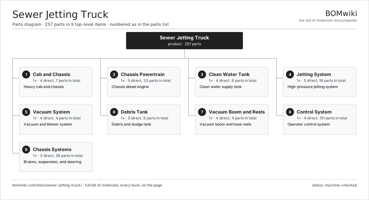
| # | Part | Qty | What it does |
|---|---|---|---|
| 1 | Cab and Chassis 4 parts | 1× | Heavy cab and chassis |
| 2 | Chassis Powertrain 5 parts | 1× | Chassis diesel engine |
| 3 | Clean Water Tank 4 parts | 1× | Clean water supply tank |
| 4 | Jetting System 5 parts | 1× | High-pressure jetting system |
| 5 | Vacuum System 4 parts | 1× | Vacuum and blower system |
| 6 | Debris Tank 5 parts | 1× | Debris and sludge tank |
| 7 | Vacuum Boom and Reels 4 parts | 1× | Vacuum boom and hose reels |
| 8 | Control System 4 parts | 1× | Operator control system |
| 9 | Chassis Systems 3 parts | 1× | Brakes, suspension, and steering |
3D model
No 3D model yet. Have a CAD file of this? Add a 3D model. STL renders right on this page; STEP, FreeCAD, and OpenSCAD sources are welcome too (openly licensed, like all 3D models on BOMwiki).
Build & assembly graph
expand / collapse · shared sub-assemblies converge · links to related products · est. labourTap an assembly to expand/collapse · tap a part to open it · use “Open page” for any node · drag to pan, scroll to zoom.
Bill of materials for Sewer Jetting Truck
9 top-level lines · 86 rows shown · 257 parts total · indented to 3 levels| # | Item / sub-assembly | Part no. | Qty/assy | Ext. qty | Parts | Type |
|---|---|---|---|---|---|---|
| 1 | Cab and Chassis 4 parts | sewer-jet-chassis | 1× | 1 | 7 | assembly |
| 1.1 | Main Frame | sewer-jet-frame | 1× | 1 | · | part |
| 1.2 | Cab | sewer-jet-cab | 1× | 1 | · | part |
| 1.3 | Sheet Metal Panel | sheet-panel | 4× | 4 | · | part |
| 1.4 | Fastener Set | fastener-set | 1× | 1 | · | part |
| 2 | Chassis Powertrain 5 parts | sewer-jet-powertrain | 1× | 1 | 33 | assembly |
| 2.1 | Chassis Engine 6 parts | sewer-jet-engine | 1× | 1 | 14 | assembly |
| 2.1.1 | Engine Block | sewer-jet-engine-block | 1× | 1 | · | part |
| 2.1.2 | Cylinder Head | sewer-jet-cylinder-head | 1× | 1 | · | part |
| 2.1.3 | Crankshaft | sewer-jet-crankshaft | 1× | 1 | · | part |
| 2.1.4 | Piston and Rod | sewer-jet-piston-set | 6× | 6 | · | part |
| 2.1.5 | Turbocharger | sewer-jet-turbo | 1× | 1 | · | part |
| 2.1.6 | Oil Seal | oil-seal | 4× | 4 | · | part |
| 2.2 | Automatic Transmission 3 parts | sewer-jet-transmission | 1× | 1 | 6 | assembly |
| 2.2.1 | Gearbox Housing | gearbox-housing | 1× | 1 | · | part |
| 2.2.2 | Helical Gear Pair | gear-pair | 4× | 4 | · | part |
| 2.2.3 | Torque Converter | sewer-jet-torque-converter | 1× | 1 | · | part |
| 2.3 | Split-Shaft PTO 3 parts | sewer-jet-pto | 1× | 1 | 3 | assembly |
| 2.3.1 | Helical Gear Pair | gear-pair | 1× | 1 | · | part |
| 2.3.2 | PTO Clutch | sewer-jet-pto-clutch | 1× | 1 | · | part |
| 2.3.3 | PTO Shaft | sewer-jet-pto-shaft | 1× | 1 | · | part |
| 2.4 | Cooling System 2 parts | sewer-jet-cooling | 1× | 1 | 2 | assembly |
| 2.4.1 | Radiator | sewer-jet-radiator | 1× | 1 | · | part |
| 2.4.2 | Cooling Fan | sewer-jet-fan | 1× | 1 | · | part |
| 2.5 | Fuel System 3 parts | sewer-jet-fuel-system | 1× | 1 | 8 | assembly |
| 2.5.1 | Fuel Tank | sewer-jet-fuel-tank | 1× | 1 | · | part |
| 2.5.2 | Injection Pump | sewer-jet-fuel-pump | 1× | 1 | · | part |
| 2.5.3 | Fuel Injector | sewer-jet-injector | 6× | 6 | · | part |
| 3 | Clean Water Tank 4 parts | sewer-jet-water-tank | 1× | 1 | 6 | assembly |
| 3.1 | Water Tank Shell | sewer-jet-water-shell | 1× | 1 | · | part |
| 3.2 | Water Baffle | sewer-jet-water-baffle | 3× | 3 | · | part |
| 3.3 | Fill Connection | sewer-jet-water-fill | 1× | 1 | · | part |
| 3.4 | Outlet Strainer | sewer-jet-water-strainer | 1× | 1 | · | part |
| 4 | Jetting System 5 parts | sewer-jet-jetting-system | 1× | 1 | 18 | assembly |
| 4.1 | Triplex Plunger Pump 4 parts | sewer-jet-triplex-pump | 1× | 1 | 11 | assembly |
| 4.1.1 | Ceramic Plunger | sewer-jet-plunger | 3× | 3 | · | part |
| 4.1.2 | Pump Crankshaft | sewer-jet-pump-crank | 1× | 1 | · | part |
| 4.1.3 | Pump Check Valve | sewer-jet-pump-valve | 6× | 6 | · | part |
| 4.1.4 | O-Ring Set | oring-set | 1× | 1 | · | part |
| 4.2 | Jet Hose | sewer-jet-jet-hose | 1× | 1 | · | part |
| 4.3 | Jet Nozzle | sewer-jet-jet-nozzle | 4× | 4 | · | part |
| 4.4 | Pressure Relief Valve | sewer-jet-pressure-relief | 1× | 1 | · | part |
| 4.5 | Pressure Sensor | pressure-sensor | 1× | 1 | · | part |
| 5 | Vacuum System 4 parts | sewer-jet-vacuum-system | 1× | 1 | 4 | assembly |
| 5.1 | Vacuum Blower | sewer-jet-blower | 1× | 1 | · | part |
| 5.2 | Cyclone Separator | sewer-jet-cyclone | 1× | 1 | · | part |
| 5.3 | Vacuum Filter | sewer-jet-vacuum-filter | 1× | 1 | · | part |
| 5.4 | Blower Silencer | sewer-jet-blower-silencer | 1× | 1 | · | part |
| 6 | Debris Tank 5 parts | sewer-jet-debris-tank | 1× | 1 | 6 | assembly |
| 6.1 | Debris Tank Shell | sewer-jet-debris-shell | 1× | 1 | · | part |
| 6.2 | Rear Door | sewer-jet-rear-door | 1× | 1 | · | part |
| 6.3 | Dump Cylinder | sewer-jet-dump-cylinder | 2× | 2 | · | part |
| 6.4 | Level Float Shutoff | sewer-jet-level-float | 1× | 1 | · | part |
| 6.5 | O-Ring Set | oring-set | 1× | 1 | · | part |
| 7 | Vacuum Boom and Reels 4 parts | sewer-jet-boom | 1× | 1 | 4 | assembly |
| 7.1 | Vacuum Boom | sewer-jet-vac-boom | 1× | 1 | · | part |
| 7.2 | Vacuum Tube Set | sewer-jet-vac-tube | 1× | 1 | · | part |
| 7.3 | Jet Hose Reel | sewer-jet-hose-reel | 1× | 1 | · | part |
| 7.4 | Reel Motor | sewer-jet-reel-motor | 1× | 1 | · | part |
| 8 | Control System 4 parts | sewer-jet-controls | 1× | 1 | 151 | assembly |
| 8.1 | Control Panel 4 parts | sewer-jet-control-panel | 1× | 1 | 143 | assembly |
| 8.1.1 | Bare PCB | pcb-bare | 1× | 1 | · | part |
| 8.1.2 | Microcontroller | mcu | 1× | 1 | · | part |
| 8.1.3 | LCD Panel | lcd-panel | 1× | 1 | · | part |
| 8.1.4 | SMD Passive (R/C/L) | smd-passives | 140× | 140 | · | part |
| 8.2 | Wireless Remote 3 parts | sewer-jet-remote | 1× | 1 | 6 | assembly |
| 8.2.1 | Bare PCB | pcb-bare | 1× | 1 | · | part |
| 8.2.2 | Microcontroller | mcu | 1× | 1 | · | part |
| 8.2.3 | Connector | connector | 4× | 4 | · | part |
| 8.3 | Pipe Inspection Camera | sewer-jet-camera | 1× | 1 | · | part |
| 8.4 | Wire Bundle | wire-bundle | 1× | 1 | · | part |
| 9 | Chassis Systems 3 parts | sewer-jet-chassis-systems | 1× | 1 | 28 | assembly |
| 9.1 | Air Brake System 5 parts | sewer-jet-brakes | 1× | 1 | 17 | assembly |
| 9.1.1 | Air Compressor | sewer-jet-air-compressor | 1× | 1 | · | part |
| 9.1.2 | Air Reservoir | sewer-jet-air-tank | 2× | 2 | · | part |
| 9.1.3 | Brake Chamber | sewer-jet-brake-chamber | 6× | 6 | · | part |
| 9.1.4 | Drum Brake | sewer-jet-drum-brake | 6× | 6 | · | part |
| 9.1.5 | Relay | relay | 2× | 2 | · | part |
| 9.2 | Suspension 3 parts | sewer-jet-suspension | 1× | 1 | 7 | assembly |
| 9.2.1 | Front Leaf Spring | sewer-jet-front-leaf | 2× | 2 | · | part |
| 9.2.2 | Tandem Rear Suspension | sewer-jet-rear-suspension | 1× | 1 | · | part |
| 9.2.3 | Shock Absorber | sewer-jet-shock | 4× | 4 | · | part |
| 9.3 | Steering System 3 parts | sewer-jet-steering | 1× | 1 | 4 | assembly |
| 9.3.1 | Steering Gear | sewer-jet-steering-gear | 1× | 1 | · | part |
| 9.3.2 | Power Steering Pump | sewer-jet-steering-pump | 1× | 1 | · | part |
| 9.3.3 | Tie Rod | sewer-jet-tie-rod | 2× | 2 | · | part |
Related products
same domain, ranked by shared parts Bulk Feed Truck
237 parts · shares 7 with this page
Bulk Feed Truck
237 parts · shares 7 with this page
 Hook-Lift Truck
252 parts · shares 6 with this page
Hook-Lift Truck
252 parts · shares 6 with this page
 Self-Loading Log Truck
313 parts · shares 6 with this page
Self-Loading Log Truck
313 parts · shares 6 with this page
 Milk Tanker Truck
147 parts · shares 6 with this page
Milk Tanker Truck
147 parts · shares 6 with this page
 Water Truck
123 parts · shares 6 with this page
Water Truck
123 parts · shares 6 with this page
 Electric Car
2,677 parts · shares 6 with this page
Electric Car
2,677 parts · shares 6 with this page
Sourcing: possible vendors
Browse the supplier directory → Prices, MOQ, and lead times are algorithmic estimates, not quotes, and not claims about these companies. Company mappings are curated by keyword; est. price band $8k–$90k. How estimates work| Vendor | HQ | Specialty | MOQ | Lead time |
|---|---|---|---|---|
|
🇯🇵Toyota
global.toyota ↗
|
Toyota City, JP | Automaker | made to order | 16–28 wks |
| volkswagen-group.com ↗ | Wolfsburg, DE | Automaker | made to order | 16–28 wks |
| gm.com ↗ | Detroit, US | Automaker | made to order | 16–28 wks |
| hyundai.com ↗ | Seoul, KR | Automaker | made to order | 16–28 wks |
|
🇨🇳BYD
byd.com ↗
|
Shenzhen, CN | EV & battery manufacturer | made to order | 16–28 wks |
882-word article