Pneumatic Tanker Truck
ProductOverview
A pneumatic tanker truck transports dry bulk powders and granules, such as cement, fly ash, lime, flour, sugar, or plastic pellets, and discharges them by fluidizing the product and blowing it under air pressure into a customer's storage silo. Unlike a liquid tanker, which simply lets gravity or a pump empty it, a powder cannot be poured reliably: fine powder packs, bridges, and refuses to flow. The pneumatic tanker solves this by turning the tank into a pressure vessel, fluidizing the powder with air through aeration pads, and carrying it as an air-suspended stream up a discharge line.
The truck is a standard rigid or articulated chassis with a diesel driveline, topped by a pressure-rated tank and the air-handling equipment that drives discharge. A control panel sequences the fluidizing and air supply systems during unloading.
Pressure vessel
The tank is a welded aluminium pressure vessel, typically alloy 5454, rated to around 2 bar and built to a pressure-vessel code such as ASME or PED. It has a cylindrical barrel closed by dished end heads, and underneath it tapers into two discharge cones where the fluidized powder collects and flows out. Product is loaded from the top through manholes. The tank rests on the chassis through saddle mounts. Because the vessel is pressurized, spring relief valves protect it from overpressure and a pressure gauge lets the operator watch tank pressure during discharge.
Fluidizing system
Powder will not flow out of a cone on its own. The fluidizing system injects low-pressure air through porous aeration pads lining the cones. Air seeps up through the fabric and lifts the powder grains apart so the bulk behaves like a fluid and slides toward the outlet. Air reaches the pads through distribution pipes and valves, and cone vibrators help dislodge any product that packs against the walls.
Air supply
The driving force for discharge comes from the air supply system. A positive-displacement roots blower, driven by the engine power take-off, delivers a large volume of air at about 2 bar. Intake air passes through a filter and the compressed air may pass an aftercooler before entering the tank. A check valve stops powder-laden air flowing back into the blower. The blower's lobe rotors are timed by a gear set so they run without contact.
Discharge piping
Fluidized powder leaves the cones and enters the discharge piping. The product line carries the air-and-powder mixture, with butterfly valves controlling which cone discharges and isolating the line. At the customer site the operator connects a flexible discharge hose through a cam-lock coupling to the silo inlet, then opens the valves and lets tank pressure push the product up to 30 m or more into the silo. Hoses stow in a hose cabinet between deliveries.
Driveline and chassis
The driveline is an inline-6 turbo diesel near 11 L with a 12-speed automated transmission. The power take-off drives the blower during discharge while the truck is stationary. The chassis uses air suspension for a stable platform under the heavy tank.
Controls and instruments
The control panel sequences the discharge so the operator does not have to juggle several systems by hand. It starts the blower, opens the aeration valves to fluidize a cone, then opens the product valves to begin the blow, watching tank pressure against the relief valve setting. The operator display shows tank pressure, blower status, and which cone is discharging. Pressure sensors on the air and product sides feed back to the control unit so it can stall the blow if pressure climbs too high, which protects both the tank and the customer's silo.
Materials and safety
The tank alloy is chosen for the pressure duty and the product. Aluminium 5454 is light, which raises payload, and it resists the alkaline attack of cement and lime. Because the vessel is a pressurized container, it is built and certified to a pressure-vessel code, fitted with redundant relief valves, and periodically inspected. Food-grade loads such as flour and sugar use tanks and hoses kept separate from cement service to avoid contamination. Static can build up while fine powder blows through the line, so the system is bonded and earthed to the silo before discharge.
Variants
The main variants are rigid versus articulated. A rigid pneumatic tanker carries a smaller load but is more manoeuvrable on tight sites, while a tractor-and-trailer combination maximizes payload for trunk hauls between plant and depot. Tank shape varies too: a single barrel with two cones is common, but some designs use a tipping tank that raises one end to help heavy powders flow to the rear cone. Blower size and aeration coverage scale with the bulk density of the typical product.
Controls, braking and use
A dual-circuit air brake system with disc brakes stops the loaded vehicle. In service the truck loads powder at a plant, drives to the customer, connects to the silo, and blows the load out in under an hour, then drives away empty with no manual handling of the product.
Pneumatic Tanker Truck parts and their functions
8 top-level parts · 207 parts in total · full bill of materials below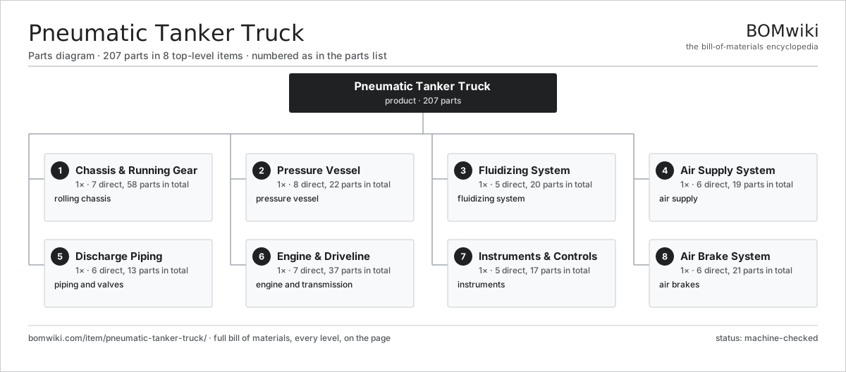
| # | Part | Qty | What it does |
|---|---|---|---|
| 1 | Chassis & Running Gear 7 parts | 1× | rolling chassis |
| 2 | Pressure Vessel 8 parts | 1× | pressure vessel |
| 3 | Fluidizing System 5 parts | 1× | fluidizing system |
| 4 | Air Supply System 6 parts | 1× | air supply |
| 5 | Discharge Piping 6 parts | 1× | piping and valves |
| 6 | Engine & Driveline 7 parts | 1× | engine and transmission |
| 7 | Instruments & Controls 5 parts | 1× | instruments |
| 8 | Air Brake System 6 parts | 1× | air brakes |
3D model
No 3D model yet. Have a CAD file of this? Add a 3D model. STL renders right on this page; STEP, FreeCAD, and OpenSCAD sources are welcome too (openly licensed, like all 3D models on BOMwiki).
Build & assembly graph
expand / collapse · shared sub-assemblies converge · links to related products · est. labourTap an assembly to expand/collapse · tap a part to open it · use “Open page” for any node · drag to pan, scroll to zoom.
Bill of materials for Pneumatic Tanker Truck
8 top-level lines · 94 rows shown · 207 parts total · indented to 3 levels| # | Item / sub-assembly | Part no. | Qty/assy | Ext. qty | Parts | Type |
|---|---|---|---|---|---|---|
| 1 | Chassis & Running Gear 7 parts | pneumatic-tanker-truck-chassis | 1× | 1 | 58 | assembly |
| 1.1 | Main Frame Rail | pneumatic-tanker-truck-main-rail | 2× | 2 | · | part |
| 1.2 | Cross Member | pneumatic-tanker-truck-cross-member | 6× | 6 | · | part |
| 1.3 | Front Steer Axle 3 parts | pneumatic-tanker-truck-axle-front | 1× | 1 | 8 | assembly |
| 1.3.1 | Steering Knuckle | pneumatic-tanker-truck-knuckle | 2× | 2 | · | part |
| 1.3.2 | Ball Bearing | ball-bearing | 4× | 4 | · | part |
| 1.3.3 | Oil Seal | oil-seal | 2× | 2 | · | part |
| 1.4 | Rear Drive Axle 3 parts | pneumatic-tanker-truck-axle-rear | 2× | 2 | 11 | assembly |
| 1.4.1 | Helical Gear Pair | gear-pair | 1× | 2 | · | part |
| 1.4.2 | Ball Bearing | ball-bearing | 6× | 12 | · | part |
| 1.4.3 | Oil Seal | oil-seal | 4× | 8 | · | part |
| 1.5 | Air Suspension Bellows | pneumatic-tanker-truck-air-spring | 4× | 4 | · | part |
| 1.6 | Wheel & Tire | pneumatic-tanker-truck-wheel | 10× | 10 | · | part |
| 1.7 | Fastener Set | fastener-set | 6× | 6 | · | part |
| 2 | Pressure Vessel 8 parts | pneumatic-tanker-truck-tank | 1× | 1 | 22 | assembly |
| 2.1 | Tank Barrel Shell | pneumatic-tanker-truck-shell | 1× | 1 | · | part |
| 2.2 | Dished End Head | pneumatic-tanker-truck-dish-end | 2× | 2 | · | part |
| 2.3 | Discharge Cone | pneumatic-tanker-truck-cone | 2× | 2 | · | part |
| 2.4 | Top Manhole 1 parts | pneumatic-tanker-truck-manhole | 2× | 2 | · | part |
| 2.4.1 | O-Ring Set | oring-set | 1× | 2 | · | part |
| 2.5 | Tank Saddle Mount | pneumatic-tanker-truck-saddle | 4× | 4 | · | part |
| 2.6 | Pressure Relief Valve 2 parts | pneumatic-tanker-truck-relief-valve | 2× | 2 | · | part |
| 2.6.1 | Coil Spring | coil-spring | 1× | 2 | · | part |
| 2.6.2 | O-Ring Set | oring-set | 1× | 2 | · | part |
| 2.7 | Pressure Gauge | pneumatic-tanker-truck-gauge | 1× | 1 | · | part |
| 2.8 | Fastener Set | fastener-set | 6× | 6 | · | part |
| 3 | Fluidizing System 5 parts | pneumatic-tanker-truck-aeration | 1× | 1 | 20 | assembly |
| 3.1 | Aeration Pad | pneumatic-tanker-truck-aeration-pad | 8× | 8 | · | part |
| 3.2 | Aeration Distribution Pipe | pneumatic-tanker-truck-aeration-pipe | 4× | 4 | · | part |
| 3.3 | Aeration Valve 1 parts | pneumatic-tanker-truck-aeration-valve | 4× | 4 | · | part |
| 3.3.1 | O-Ring Set | oring-set | 1× | 4 | · | part |
| 3.4 | Cone Vibrator | pneumatic-tanker-truck-vibrator | 2× | 2 | · | part |
| 3.5 | O-Ring Set | oring-set | 2× | 2 | · | part |
| 4 | Air Supply System 6 parts | pneumatic-tanker-truck-compressor | 1× | 1 | 19 | assembly |
| 4.1 | Positive-Displacement Blower 5 parts | pneumatic-tanker-truck-pd-blower | 1× | 1 | 10 | assembly |
| 4.1.1 | Lobe Rotor | pneumatic-tanker-truck-blower-rotor | 2× | 2 | · | part |
| 4.1.2 | Blower Housing | pneumatic-tanker-truck-blower-housing | 1× | 1 | · | part |
| 4.1.3 | Helical Gear Pair | gear-pair | 1× | 1 | · | part |
| 4.1.4 | Ball Bearing | ball-bearing | 4× | 4 | · | part |
| 4.1.5 | Oil Seal | oil-seal | 2× | 2 | · | part |
| 4.2 | Intake Air Filter | pneumatic-tanker-truck-air-filter | 1× | 1 | · | part |
| 4.3 | Air Aftercooler | pneumatic-tanker-truck-aftercooler | 1× | 1 | · | part |
| 4.4 | Air Check Valve 1 parts | pneumatic-tanker-truck-check-valve | 1× | 1 | · | part |
| 4.4.1 | Coil Spring | coil-spring | 1× | 1 | · | part |
| 4.5 | Air Supply Pipe | pneumatic-tanker-truck-air-pipe | 4× | 4 | · | part |
| 4.6 | Pressure Sensor | pressure-sensor | 2× | 2 | · | part |
| 5 | Discharge Piping 6 parts | pneumatic-tanker-truck-discharge | 1× | 1 | 13 | assembly |
| 5.1 | Product Pipe Line | pneumatic-tanker-truck-product-line | 1× | 1 | · | part |
| 5.2 | Butterfly Valve 1 parts | pneumatic-tanker-truck-butterfly | 4× | 4 | · | part |
| 5.2.1 | O-Ring Set | oring-set | 1× | 4 | · | part |
| 5.3 | Flexible Discharge Hose | pneumatic-tanker-truck-flexhose | 2× | 2 | · | part |
| 5.4 | Cam-Lock Coupling 1 parts | pneumatic-tanker-truck-coupling | 2× | 2 | · | part |
| 5.4.1 | O-Ring Set | oring-set | 1× | 2 | · | part |
| 5.5 | Pipe Elbow | pneumatic-tanker-truck-elbow | 3× | 3 | · | part |
| 5.6 | Hose Storage Cabinet | pneumatic-tanker-truck-cabinet | 1× | 1 | · | part |
| 6 | Engine & Driveline 7 parts | pneumatic-tanker-truck-driveline | 1× | 1 | 37 | assembly |
| 6.1 | Diesel Engine 5 parts | pneumatic-tanker-truck-engine | 1× | 1 | 14 | assembly |
| 6.1.1 | Cylinder Block | pneumatic-tanker-truck-block | 1× | 1 | · | part |
| 6.1.2 | Crankshaft | pneumatic-tanker-truck-crankshaft | 1× | 1 | · | part |
| 6.1.3 | Engine Piston | pneumatic-tanker-truck-piston-eng | 6× | 6 | · | part |
| 6.1.4 | Turbocharger 1 parts + deeper › | pneumatic-tanker-truck-turbo | 1× | 1 | · | part |
| 6.1.5 | Oil Seal | oil-seal | 4× | 4 | · | part |
| 6.2 | Automated Manual Transmission 4 parts | pneumatic-tanker-truck-transmission | 1× | 1 | 18 | assembly |
| 6.2.1 | Gearbox Housing | gearbox-housing | 1× | 1 | · | part |
| 6.2.2 | Helical Gear Pair | gear-pair | 6× | 6 | · | part |
| 6.2.3 | Ball Bearing | ball-bearing | 8× | 8 | · | part |
| 6.2.4 | Oil Seal | oil-seal | 3× | 3 | · | part |
| 6.3 | Power Take-Off 1 parts | pneumatic-tanker-truck-pto | 1× | 1 | · | part |
| 6.3.1 | Helical Gear Pair | gear-pair | 1× | 1 | · | part |
| 6.4 | Clutch Assembly | pneumatic-tanker-truck-clutch | 1× | 1 | · | part |
| 6.5 | Propeller Shaft | pneumatic-tanker-truck-prop-shaft | 1× | 1 | · | part |
| 6.6 | Radiator | pneumatic-tanker-truck-radiator | 1× | 1 | · | part |
| 6.7 | Fuel Tank | pneumatic-tanker-truck-fuel-tank | 1× | 1 | · | part |
| 7 | Instruments & Controls 5 parts | pneumatic-tanker-truck-controls | 1× | 1 | 17 | assembly |
| 7.1 | Discharge Control Panel 3 parts | pneumatic-tanker-truck-control-panel | 1× | 1 | · | part |
| 7.1.1 | Bare PCB | pcb-bare | 1× | 1 | · | part |
| 7.1.2 | Microcontroller | mcu | 1× | 1 | · | part |
| 7.1.3 | SMD Passive (R/C/L) | smd-passives | 1× | 1 | · | part |
| 7.2 | Operator Display 1 parts | pneumatic-tanker-truck-display | 1× | 1 | · | part |
| 7.2.1 | LCD Panel | lcd-panel | 1× | 1 | · | part |
| 7.3 | Wire Bundle | wire-bundle | 1× | 1 | · | part |
| 7.4 | Relay | relay | 4× | 4 | · | part |
| 7.5 | Connector | connector | 8× | 8 | · | part |
| 8 | Air Brake System 6 parts | pneumatic-tanker-truck-brakes | 1× | 1 | 21 | assembly |
| 8.1 | Brake Air Compressor 2 parts | pneumatic-tanker-truck-brake-compressor | 1× | 1 | · | part |
| 8.1.1 | Ball Bearing | ball-bearing | 2× | 2 | · | part |
| 8.1.2 | O-Ring Set | oring-set | 1× | 1 | · | part |
| 8.2 | Brake Air Reservoir | pneumatic-tanker-truck-air-tank | 3× | 3 | · | part |
| 8.3 | Brake Chamber 1 parts | pneumatic-tanker-truck-brake-chamber | 6× | 6 | · | part |
| 8.3.1 | Coil Spring | coil-spring | 1× | 6 | · | part |
| 8.4 | Brake Disc | pneumatic-tanker-truck-disc | 6× | 6 | · | part |
| 8.5 | Foot Brake Valve 1 parts | pneumatic-tanker-truck-valve-foot | 1× | 1 | · | part |
| 8.5.1 | O-Ring Set | oring-set | 1× | 1 | · | part |
| 8.6 | Pressure Sensor | pressure-sensor | 2× | 2 | · | part |
Related products
same domain, ranked by shared parts Bulk Feed Truck
237 parts · shares 7 with this page
Bulk Feed Truck
237 parts · shares 7 with this page
 Coupe Car
1,617 parts · shares 7 with this page
Coupe Car
1,617 parts · shares 7 with this page
 Crew Cab Pickup
1,009 parts · shares 7 with this page
Crew Cab Pickup
1,009 parts · shares 7 with this page
 Rally Car
424 parts · shares 7 with this page
Rally Car
424 parts · shares 7 with this page
 Station Wagon
1,657 parts · shares 7 with this page
Station Wagon
1,657 parts · shares 7 with this page
 Parcel Delivery Van
429 parts · shares 6 with this page
Parcel Delivery Van
429 parts · shares 6 with this page
Sourcing: possible vendors
Browse the supplier directory → Prices, MOQ, and lead times are algorithmic estimates, not quotes, and not claims about these companies. Company mappings are curated by keyword; est. price band $8k–$90k. How estimates work| Vendor | HQ | Specialty | MOQ | Lead time |
|---|---|---|---|---|
|
🇯🇵Toyota
global.toyota ↗
|
Toyota City, JP | Automaker | made to order | 16–28 wks |
| volkswagen-group.com ↗ | Wolfsburg, DE | Automaker | made to order | 16–28 wks |
| gm.com ↗ | Detroit, US | Automaker | made to order | 16–28 wks |
| hyundai.com ↗ | Seoul, KR | Automaker | made to order | 16–28 wks |
|
🇨🇳BYD
byd.com ↗
|
Shenzhen, CN | EV & battery manufacturer | made to order | 16–28 wks |
1,058-word article