Street Sweeper Truck
ProductOverview
A street sweeper truck cleans paved road surfaces by sweeping debris with rotating brooms into a vacuum pickup that carries it to an onboard hopper. The machine combines a road chassis with a dedicated sweeping system: side gutter brooms pull debris from the curb to the center, a wide main broom lifts it into the airflow, and a suction fan draws the debris into the hopper while a water system keeps dust down. Most designs use two engines, one to drive the truck and a second to power the sweeping equipment independently of road speed.
The vehicle joins the Cab and Chassis, a medium-duty cab and ladder frame, with the Chassis Powertrain that propels the truck and the Auxiliary Engine that runs the sweeping system. The Broom System and Vacuum System do the cleaning, the Debris Hopper holds the collected debris, the Water System suppresses dust, and the Sweeper Controls let the operator manage everything from a dual-control cab.
Chassis and propulsion
The Ladder Frame is a box-section steel ladder carrying the hopper, brooms, and auxiliary engine. The Dual-Control Cab has dual controls, with left and right steering and pedals, so the operator can sweep against either curb without crossing lanes. The Chassis Engine is a 6.7 L diesel producing 260 hp from a cast iron Engine Block under boost from a Turbocharger. The Automatic Transmission is a six-speed automatic whose Torque Converter gives smooth control at the 5 to 8 mph sweeping pace, and the Cooling System system uses a reversing Cooling Fan that periodically blows debris off the cooling fins.
Auxiliary engine and hydraulics
The Auxiliary Engine is a separate four-cylinder diesel that drives the sweeping system so broom and fan speed stay constant regardless of road speed. Its Hydraulic Pump draws from a Hydraulic Reservoir reservoir and feeds a Hydraulic Valve Bank bank that distributes flow to the broom, lift, and fan motors. Splitting propulsion from sweeping lets the operator slow for heavy debris without starving the brooms or speed up on a clean stretch without overspinning them.
Broom system
The Broom System starts with two angled Gutter Broom discs. Each uses a steel Broom Disc hub carrying a replaceable Bristle Set that sweeps debris from the gutter toward the center of the truck. The cylindrical Main Broom then lifts that debris into the pickup path, driven by a hydraulic Broom Drive Motor on its Broom Core. Hydraulic Broom Lift Cylinder cylinders lower each broom to the road for work and raise it for transit, and bristles are swapped on a wear schedule.
Vacuum and hopper
The Vacuum System uses a high-volume Suction Fan driven by a Fan Drive Motor to draw air through a ground-following Pickup Head. The debris-laden air travels up a flexible Suction Duct into the Debris Hopper. The Hopper Shell holds roughly five cubic yards, a Dust Filter traps fine dust in the fan exhaust so it does not blow back into the air, and hydraulic Dump Cylinder units tilt the hopper to empty it through the Discharge Door into a transfer bin.
Water and dust suppression
The Water System keeps airborne dust within legal limits. A polyethylene Water Tank feeds an electric Water Pump that supplies a set of fine-mist Spray Nozzle outputs at the brooms and the pickup head. Wetting the debris as it is disturbed holds the dust down, which matters for both air-quality rules and operator visibility.
Controls and chassis systems
The Sweeper Controls center on a Control Panel with a status display, a Broom Joystick that positions the gutter brooms and sets their down pressure, and Broom Camera views so the operator watches the broom path against the curb. The Chassis Systems provide the road functions: Air Brake System are dual-circuit air brakes with an engine-driven Air Compressor and Drum Brake units, the Suspension uses leaf springs and dampers, and the Steering System is hydraulic power steering serving both control positions. The dual controls let the operator drive from whichever side faces the curb being swept, which keeps the broom path in clear view and avoids reaching across the cab.
In service, sweepers run scheduled routes at low speed, dump the hopper at a transfer site when full, and refill the water tank between passes. The two-engine layout, the gutter-to-center broom path, and the vacuum pickup are the features that separate a mechanical sweeper from a simple brush attachment, and each addresses part of the job: holding broom speed steady, gathering debris from the curb line, and lifting it into the hopper rather than scattering it. Operators match broom down-pressure and water flow to the debris they encounter, easing off on a clean stretch and bearing down on packed leaves or sand. Crews replace worn bristles often, since the broom is the highest-wear part, and clean the dust filter to keep airflow and pickup performance up. Regenerative-style routes that sweep the same streets repeatedly stress the brooms and the hopper dump mechanism most, so those components set the service schedule.
Street Sweeper Truck parts and their functions
9 top-level parts · 223 parts in total · full bill of materials below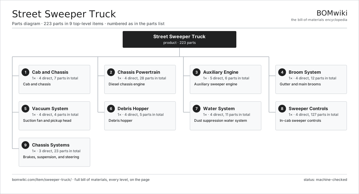
| # | Part | Qty | What it does |
|---|---|---|---|
| 1 | Cab and Chassis 4 parts | 1× | Cab and chassis |
| 2 | Chassis Powertrain 4 parts | 1× | Diesel chassis engine |
| 3 | Auxiliary Engine 5 parts | 1× | Auxiliary sweeper engine |
| 4 | Broom System 4 parts | 1× | Gutter and main brooms |
| 5 | Vacuum System 4 parts | 1× | Suction fan and pickup head |
| 6 | Debris Hopper 4 parts | 1× | Debris hopper |
| 7 | Water System 4 parts | 1× | Dust suppression water system |
| 8 | Sweeper Controls 4 parts | 1× | In-cab sweeper controls |
| 9 | Chassis Systems 3 parts | 1× | Brakes, suspension, and steering |
3D model
No 3D model yet. Have a CAD file of this? Add a 3D model. STL renders right on this page; STEP, FreeCAD, and OpenSCAD sources are welcome too (openly licensed, like all 3D models on BOMwiki).
Build & assembly graph
expand / collapse · shared sub-assemblies converge · links to related products · est. labourTap an assembly to expand/collapse · tap a part to open it · use “Open page” for any node · drag to pan, scroll to zoom.
Bill of materials for Street Sweeper Truck
9 top-level lines · 75 rows shown · 223 parts total · indented to 3 levels| # | Item / sub-assembly | Part no. | Qty/assy | Ext. qty | Parts | Type |
|---|---|---|---|---|---|---|
| 1 | Cab and Chassis 4 parts | sweeper-truck-chassis | 1× | 1 | 7 | assembly |
| 1.1 | Ladder Frame | sweeper-truck-frame | 1× | 1 | · | part |
| 1.2 | Dual-Control Cab | sweeper-truck-cab | 1× | 1 | · | part |
| 1.3 | Sheet Metal Panel | sheet-panel | 4× | 4 | · | part |
| 1.4 | Fastener Set | fastener-set | 1× | 1 | · | part |
| 2 | Chassis Powertrain 4 parts | sweeper-truck-powertrain | 1× | 1 | 28 | assembly |
| 2.1 | Chassis Engine 5 parts | sweeper-truck-engine | 1× | 1 | 13 | assembly |
| 2.1.1 | Engine Block | sweeper-truck-engine-block | 1× | 1 | · | part |
| 2.1.2 | Cylinder Head | sweeper-truck-cylinder-head | 1× | 1 | · | part |
| 2.1.3 | Piston and Rod | sweeper-truck-piston-set | 6× | 6 | · | part |
| 2.1.4 | Turbocharger | sweeper-truck-turbo | 1× | 1 | · | part |
| 2.1.5 | Oil Seal | oil-seal | 4× | 4 | · | part |
| 2.2 | Automatic Transmission 3 parts | sweeper-truck-transmission | 1× | 1 | 5 | assembly |
| 2.2.1 | Gearbox Housing | gearbox-housing | 1× | 1 | · | part |
| 2.2.2 | Helical Gear Pair | gear-pair | 3× | 3 | · | part |
| 2.2.3 | Torque Converter | sweeper-truck-torque-converter | 1× | 1 | · | part |
| 2.3 | Cooling System 2 parts | sweeper-truck-cooling | 1× | 1 | 2 | assembly |
| 2.3.1 | Radiator | sweeper-truck-radiator | 1× | 1 | · | part |
| 2.3.2 | Cooling Fan | sweeper-truck-fan | 1× | 1 | · | part |
| 2.4 | Fuel System 3 parts | sweeper-truck-fuel-system | 1× | 1 | 8 | assembly |
| 2.4.1 | Fuel Tank | sweeper-truck-fuel-tank | 1× | 1 | · | part |
| 2.4.2 | Fuel Pump | sweeper-truck-fuel-pump | 1× | 1 | · | part |
| 2.4.3 | Fuel Injector | sweeper-truck-injector | 6× | 6 | · | part |
| 3 | Auxiliary Engine 5 parts | sweeper-truck-aux-engine | 1× | 1 | 6 | assembly |
| 3.1 | Auxiliary Engine Block | sweeper-truck-aux-block | 1× | 1 | · | part |
| 3.2 | Hydraulic Pump | sweeper-truck-hydraulic-pump | 1× | 1 | · | part |
| 3.3 | Hydraulic Reservoir | sweeper-truck-hydraulic-tank | 1× | 1 | · | part |
| 3.4 | Hydraulic Valve Bank | sweeper-truck-hydraulic-valve | 1× | 1 | · | part |
| 3.5 | Oil Seal | oil-seal | 2× | 2 | · | part |
| 4 | Broom System 4 parts | sweeper-truck-broom-system | 1× | 1 | 12 | assembly |
| 4.1 | Gutter Broom 2 parts | sweeper-truck-gutter-broom | 2× | 2 | 2 | assembly |
| 4.1.1 | Broom Disc | sweeper-truck-broom-disc | 1× | 2 | · | part |
| 4.1.2 | Bristle Set | sweeper-truck-bristle-set | 1× | 2 | · | part |
| 4.2 | Main Broom 2 parts | sweeper-truck-main-broom | 1× | 1 | 2 | assembly |
| 4.2.1 | Broom Core | sweeper-truck-broom-core | 1× | 1 | · | part |
| 4.2.2 | Bristle Set | sweeper-truck-bristle-set | 1× | 1 | · | part |
| 4.3 | Broom Drive Motor | sweeper-truck-broom-motor | 3× | 3 | · | part |
| 4.4 | Broom Lift Cylinder | sweeper-truck-broom-lift | 3× | 3 | · | part |
| 5 | Vacuum System 4 parts | sweeper-truck-vacuum-system | 1× | 1 | 4 | assembly |
| 5.1 | Suction Fan | sweeper-truck-suction-fan | 1× | 1 | · | part |
| 5.2 | Pickup Head | sweeper-truck-pickup-head | 1× | 1 | · | part |
| 5.3 | Suction Duct | sweeper-truck-suction-duct | 1× | 1 | · | part |
| 5.4 | Fan Drive Motor | sweeper-truck-fan-motor | 1× | 1 | · | part |
| 6 | Debris Hopper 4 parts | sweeper-truck-hopper | 1× | 1 | 5 | assembly |
| 6.1 | Hopper Shell | sweeper-truck-hopper-shell | 1× | 1 | · | part |
| 6.2 | Dust Filter | sweeper-truck-dust-filter | 1× | 1 | · | part |
| 6.3 | Dump Cylinder | sweeper-truck-dump-cylinder | 2× | 2 | · | part |
| 6.4 | Discharge Door | sweeper-truck-hopper-door | 1× | 1 | · | part |
| 7 | Water System 4 parts | sweeper-truck-water-system | 1× | 1 | 11 | assembly |
| 7.1 | Water Tank | sweeper-truck-water-tank | 1× | 1 | · | part |
| 7.2 | Water Pump | sweeper-truck-water-pump | 1× | 1 | · | part |
| 7.3 | Spray Nozzle | sweeper-truck-spray-nozzle | 8× | 8 | · | part |
| 7.4 | O-Ring Set | oring-set | 1× | 1 | · | part |
| 8 | Sweeper Controls 4 parts | sweeper-truck-controls | 1× | 1 | 127 | assembly |
| 8.1 | Control Panel 4 parts | sweeper-truck-control-panel | 1× | 1 | 123 | assembly |
| 8.1.1 | Bare PCB | pcb-bare | 1× | 1 | · | part |
| 8.1.2 | Microcontroller | mcu | 1× | 1 | · | part |
| 8.1.3 | LCD Panel | lcd-panel | 1× | 1 | · | part |
| 8.1.4 | SMD Passive (R/C/L) | smd-passives | 120× | 120 | · | part |
| 8.2 | Broom Joystick | sweeper-truck-joystick | 1× | 1 | · | part |
| 8.3 | Broom Camera | sweeper-truck-camera | 2× | 2 | · | part |
| 8.4 | Wire Bundle | wire-bundle | 1× | 1 | · | part |
| 9 | Chassis Systems 3 parts | sweeper-truck-chassis-systems | 1× | 1 | 23 | assembly |
| 9.1 | Air Brake System 4 parts | sweeper-truck-brakes | 1× | 1 | 11 | assembly |
| 9.1.1 | Air Compressor | sweeper-truck-air-compressor | 1× | 1 | · | part |
| 9.1.2 | Brake Chamber | sweeper-truck-brake-chamber | 4× | 4 | · | part |
| 9.1.3 | Drum Brake | sweeper-truck-drum-brake | 4× | 4 | · | part |
| 9.1.4 | Relay | relay | 2× | 2 | · | part |
| 9.2 | Suspension 2 parts | sweeper-truck-suspension | 1× | 1 | 8 | assembly |
| 9.2.1 | Leaf Spring | sweeper-truck-leaf-spring | 4× | 4 | · | part |
| 9.2.2 | Shock Absorber | sweeper-truck-shock | 4× | 4 | · | part |
| 9.3 | Steering System 3 parts | sweeper-truck-steering | 1× | 1 | 4 | assembly |
| 9.3.1 | Steering Gear | sweeper-truck-steering-gear | 1× | 1 | · | part |
| 9.3.2 | Power Steering Pump | sweeper-truck-steering-pump | 1× | 1 | · | part |
| 9.3.3 | Tie Rod | sweeper-truck-tie-rod | 2× | 2 | · | part |
Related products
same domain, ranked by shared parts Bulk Feed Truck
237 parts · shares 6 with this page
Bulk Feed Truck
237 parts · shares 6 with this page
 Electric Car
2,677 parts · shares 6 with this page
Electric Car
2,677 parts · shares 6 with this page
 Plug-In Hybrid Car
1,523 parts · shares 6 with this page
Sewer Jetting Truck
257 parts · shares 6 with this page
Plug-In Hybrid Car
1,523 parts · shares 6 with this page
Sewer Jetting Truck
257 parts · shares 6 with this page
 Hook-Lift Truck
252 parts · shares 5 with this page
Hook-Lift Truck
252 parts · shares 5 with this page
 Self-Loading Log Truck
313 parts · shares 5 with this page
Self-Loading Log Truck
313 parts · shares 5 with this page
Sourcing: possible vendors
Browse the supplier directory → Prices, MOQ, and lead times are algorithmic estimates, not quotes, and not claims about these companies. Company mappings are curated by keyword; est. price band $8k–$90k. How estimates work| Vendor | HQ | Specialty | MOQ | Lead time |
|---|---|---|---|---|
|
🇯🇵Toyota
global.toyota ↗
|
Toyota City, JP | Automaker | made to order | 16–28 wks |
| volkswagen-group.com ↗ | Wolfsburg, DE | Automaker | made to order | 16–28 wks |
| gm.com ↗ | Detroit, US | Automaker | made to order | 16–28 wks |
| hyundai.com ↗ | Seoul, KR | Automaker | made to order | 16–28 wks |
|
🇨🇳BYD
byd.com ↗
|
Shenzhen, CN | EV & battery manufacturer | made to order | 16–28 wks |
936-word article