Sand Rail Buggy
ProductOverview
A sand rail buggy, often just called a rail, is a vehicle stripped to the parts that move it across loose sand and nothing else. It has no doors, no roof, and almost no body panels. What remains is a welded tube skeleton, an engine, suspension, and tires, which is why it weighs a fraction of a normal car and accelerates hard even on a surface that swallows ordinary tires. The whole design is shaped around dune driving: light weight to float over soft sand, long suspension travel to absorb jumps, and rear tires that grip a surface with no firm footing.
The Space Frame is the foundation, a tubular cage that serves as chassis and rollover protection in one. Behind the cockpit sits the Powertrain, an air-cooled engine and combined transaxle. Each wheel hangs from long-travel suspension, the Front Suspension using double A-arms and the Rear Suspension using trailing arms. The driver controls the rail through the Steering and Brakes, rides in the Cockpit, and the Wheels & Tires convert engine torque into forward motion on sand. A small Electrical System system and a Fuel System round out the build.
Space frame and structure
Everything bolts to the space frame. It is made from 4130 chromoly tubing, bent and welded into a triangulated structure that resists twisting far better than its light weight suggests. The Main Roll Hoop arches over the driver as the main rollover member, and the Side Tube tie it into a rigid cell. Flat Gusset Plate inserts are welded into the tube junctions to spread load where bending would otherwise concentrate at a single joint.
A welded Floor Pan closes the lower cockpit and adds shear stiffness, while the Engine Cradle at the rear carries the heavy powertrain and feeds its loads into the frame. A Skid Plate underneath protects the belly when the rail bottoms out over a ridge. Because there is no body to add rigidity, the tube frame alone has to carry every load from the suspension, engine, and crash forces, so the tube routing is as much a structural design as a packaging one.
Powertrain
Most rails use an air-cooled flat-four Air-Cooled Engine mounted behind the seats. Air cooling avoids the radiator and plumbing of a liquid system, which matters in sand where a radiator clogs quickly, and the flat layout sits low for a low center of gravity. The Cooling Fan forces air through shrouds over the finned Cylinder Barrel barrels, and an Oil Cooler handles the heat the air cannot carry off during sustained climbs.
Power flows through the Clutch into the Transaxle, a single unit that combines the gearbox and final drive between the rear wheels. Inside, several Helical Gear Pair sets ride on bearings, and a Differential splits torque to the two CV Drive Axle shafts. The CV joints let the axles flex with the long suspension travel while still delivering smooth torque. A tuned Exhaust Header header and dual Carburetor units help the engine breathe for the sharp throttle response a dune climb demands.
Suspension and tires
Suspension travel is the defining feature of a rail. The Front Suspension uses Upper Control Arm and Lower Control Arm links with a Coilover Shock at each corner, giving the front wheels long, controlled movement. The Rear Suspension uses a Trailing Arm per side with twin coilovers and a Bump Stop that absorbs the final inches of travel during a hard landing. A Torsion Bar limits body roll so the rail stays planted in turns.
The Wheels & Tires are matched to the surface. Front Rib Tire units have raised guide ribs that knife into the sand for steering bite, while rear Paddle Tire units carry molded scoops that paddle against the loose surface to put power down. The wheels are Beadlock Wheel rims that clamp the tire bead mechanically, letting the driver run very low pressure for a large contact patch without the tire unseating.
Steering, brakes, and cockpit
Steering is direct and quick. A Steering Rack converts the wheel input from the Steering Column into Tie Rod motion at the spindles, and the gearing is fast so small inputs turn the wheels sharply on a surface that resists steering. Braking uses Brake Disc rotors at all four corners gripped by Brake Caliper units, with two Master Cylinder units and a Balance Bar that lets the driver bias braking front to rear.
Inside, the Cockpit holds Bucket Seat shells with five-point Safety Harness belts to keep occupants in place during jumps and the occasional roll. The Pedal Box, Shifter, and a small Gauge Cluster make up the controls. The fuel comes from a foam-filled Fuel Cell that resists slosh and leaks, and a minimal Electrical System system with a Kill Switch keeps weight and complexity down.
Variants and use
Rails range from small single-seat machines built around a 1600 cc engine to wide two-seat dune cars with turbocharged engines making well over 200 horsepower. Some builders favor pure dune use with extreme paddle tires and long travel, while others build dual-purpose rails that can also run hard-packed desert trails. They are recreational vehicles first, used at sand recreation areas and in amateur desert events, and they are rarely street legal because they lack the lights, signals, and bodywork that road registration requires.
Sand Rail Buggy parts and their functions
10 top-level parts · 197 parts in total · full bill of materials below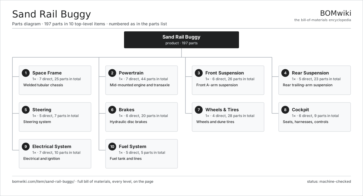
| # | Part | Qty | What it does |
|---|---|---|---|
| 1 | Space Frame 7 parts | 1× | Welded tubular chassis |
| 2 | Powertrain 7 parts | 1× | Mid-mounted engine and transaxle |
| 3 | Front Suspension 6 parts | 1× | Front A-arm suspension |
| 4 | Rear Suspension 5 parts | 1× | Rear trailing-arm suspension |
| 5 | Steering 5 parts | 1× | Steering system |
| 6 | Brakes 6 parts | 1× | Hydraulic disc brakes |
| 7 | Wheels & Tires 4 parts | 1× | Wheels and dune tires |
| 8 | Cockpit 6 parts | 1× | Seats, harnesses, controls |
| 9 | Electrical System 7 parts | 1× | Electrical and ignition |
| 10 | Fuel System 5 parts | 1× | Fuel tank and lines |
3D model
No 3D model yet. Have a CAD file of this? Add a 3D model. STL renders right on this page; STEP, FreeCAD, and OpenSCAD sources are welcome too (openly licensed, like all 3D models on BOMwiki).
Build & assembly graph
expand / collapse · shared sub-assemblies converge · links to related products · est. labourTap an assembly to expand/collapse · tap a part to open it · use “Open page” for any node · drag to pan, scroll to zoom.
Bill of materials for Sand Rail Buggy
10 top-level lines · 89 rows shown · 197 parts total · indented to 3 levels| # | Item / sub-assembly | Part no. | Qty/assy | Ext. qty | Parts | Type |
|---|---|---|---|---|---|---|
| 1 | Space Frame 7 parts | srb-space-frame | 1× | 1 | 25 | assembly |
| 1.1 | Main Roll Hoop | srb-main-hoop | 1× | 1 | · | part |
| 1.2 | Side Tube | srb-side-tubes | 8× | 8 | · | part |
| 1.3 | Floor Pan | srb-floor-pan | 1× | 1 | · | part |
| 1.4 | Engine Cradle | srb-engine-cradle | 1× | 1 | · | part |
| 1.5 | Gusset Plate | srb-gusset-plate | 12× | 12 | · | part |
| 1.6 | Skid Plate | srb-skid-plate | 1× | 1 | · | part |
| 1.7 | Fastener Set | fastener-set | 1× | 1 | · | part |
| 2 | Powertrain 7 parts | srb-powertrain | 1× | 1 | 44 | assembly |
| 2.1 | Air-Cooled Engine 8 parts | srb-engine | 1× | 1 | 16 | assembly |
| 2.1.1 | Crankcase | srb-engine-block | 1× | 1 | · | part |
| 2.1.2 | Cylinder Barrel | srb-cylinder | 4× | 4 | · | part |
| 2.1.3 | Piston | srb-piston | 4× | 4 | · | part |
| 2.1.4 | Crankshaft | srb-crankshaft | 1× | 1 | · | part |
| 2.1.5 | Cylinder Head | srb-cylinder-head | 2× | 2 | · | part |
| 2.1.6 | Cooling Fan | srb-cooling-fan | 1× | 1 | · | part |
| 2.1.7 | Carburetor | srb-carburetor | 2× | 2 | · | part |
| 2.1.8 | O-Ring Set | oring-set | 1× | 1 | · | part |
| 2.2 | Transaxle 7 parts | srb-transaxle | 1× | 1 | 20 | assembly |
| 2.2.1 | Gearbox Housing | gearbox-housing | 1× | 1 | · | part |
| 2.2.2 | Helical Gear Pair | gear-pair | 4× | 4 | · | part |
| 2.2.3 | Shift Fork | srb-shift-fork | 3× | 3 | · | part |
| 2.2.4 | Differential | srb-differential | 1× | 1 | · | part |
| 2.2.5 | Ball Bearing | ball-bearing | 6× | 6 | · | part |
| 2.2.6 | Oil Seal | oil-seal | 4× | 4 | · | part |
| 2.2.7 | Gear Oil | srb-gear-oil | 1× | 1 | · | part |
| 2.3 | Clutch | srb-clutch | 1× | 1 | · | part |
| 2.4 | CV Drive Axle | srb-cv-axle | 2× | 2 | · | part |
| 2.5 | Exhaust Header | srb-exhaust | 1× | 1 | · | part |
| 2.6 | Oil Cooler | srb-oil-cooler | 1× | 1 | · | part |
| 2.7 | Engine Mount | srb-engine-mount | 3× | 3 | · | part |
| 3 | Front Suspension 6 parts | srb-front-suspension | 1× | 1 | 26 | assembly |
| 3.1 | Upper Control Arm | srb-upper-arm | 2× | 2 | · | part |
| 3.2 | Lower Control Arm | srb-lower-arm | 2× | 2 | · | part |
| 3.3 | Coilover Shock | srb-coilover | 2× | 2 | · | part |
| 3.4 | Spindle | srb-spindle | 2× | 2 | · | part |
| 3.5 | Ball Joint | srb-ball-joint | 4× | 4 | · | part |
| 3.6 | Wheel Hub 3 parts | wheel-hub | 2× | 2 | 7 | assembly |
| 3.6.1 | Wheel Hub Bearing | hub-bearing | 1× | 2 | · | part |
| 3.6.2 | Hub Flange | hub-flange | 1× | 2 | · | part |
| 3.6.3 | Wheel Stud | wheel-stud | 5× | 10 | · | part |
| 4 | Rear Suspension 5 parts | srb-rear-suspension | 1× | 1 | 23 | assembly |
| 4.1 | Trailing Arm | srb-trailing-arm | 2× | 2 | · | part |
| 4.2 | Coilover Shock | srb-coilover | 4× | 4 | · | part |
| 4.3 | Bump Stop | srb-bump-stop | 2× | 2 | · | part |
| 4.4 | Wheel Hub 3 parts | wheel-hub | 2× | 2 | 7 | assembly |
| 4.4.1 | Wheel Hub Bearing | hub-bearing | 1× | 2 | · | part |
| 4.4.2 | Hub Flange | hub-flange | 1× | 2 | · | part |
| 4.4.3 | Wheel Stud | wheel-stud | 5× | 10 | · | part |
| 4.5 | Torsion Bar | srb-torsion-bar | 1× | 1 | · | part |
| 5 | Steering 5 parts | srb-steering | 1× | 1 | 7 | assembly |
| 5.1 | Steering Rack | srb-steering-rack | 1× | 1 | · | part |
| 5.2 | Tie Rod | srb-tie-rod | 2× | 2 | · | part |
| 5.3 | Steering Column | srb-steering-column | 1× | 1 | · | part |
| 5.4 | Steering Wheel | srb-steering-wheel | 1× | 1 | · | part |
| 5.5 | Universal Joint | srb-u-joint | 2× | 2 | · | part |
| 6 | Brakes 6 parts | srb-brakes | 1× | 1 | 20 | assembly |
| 6.1 | Brake Disc | srb-brake-disc | 4× | 4 | · | part |
| 6.2 | Brake Caliper | srb-brake-caliper | 4× | 4 | · | part |
| 6.3 | Master Cylinder | srb-master-cylinder | 2× | 2 | · | part |
| 6.4 | Balance Bar | srb-balance-bar | 1× | 1 | · | part |
| 6.5 | Brake Lines | srb-brake-line | 1× | 1 | · | part |
| 6.6 | Brake Pad | srb-brake-pad | 8× | 8 | · | part |
| 7 | Wheels & Tires 4 parts | srb-wheels-tires | 1× | 1 | 28 | assembly |
| 7.1 | Beadlock Wheel | srb-beadlock-wheel | 4× | 4 | · | part |
| 7.2 | Paddle Tire | srb-paddle-tire | 2× | 2 | · | part |
| 7.3 | Rib Tire | srb-rib-tire | 2× | 2 | · | part |
| 7.4 | Lug Nut | srb-lug-nut | 20× | 20 | · | part |
| 8 | Cockpit 6 parts | srb-cockpit | 1× | 1 | 9 | assembly |
| 8.1 | Bucket Seat | srb-bucket-seat | 2× | 2 | · | part |
| 8.2 | Safety Harness | srb-harness | 2× | 2 | · | part |
| 8.3 | Pedal Box | srb-pedal-box | 1× | 1 | · | part |
| 8.4 | Shifter | srb-shifter | 1× | 1 | · | part |
| 8.5 | Gauge Cluster | srb-gauge-cluster | 1× | 1 | · | part |
| 8.6 | Grab Handle | srb-grab-handle | 2× | 2 | · | part |
| 9 | Electrical System 7 parts | srb-electrical | 1× | 1 | 10 | assembly |
| 9.1 | Battery | srb-battery | 1× | 1 | · | part |
| 9.2 | Alternator | srb-alternator | 1× | 1 | · | part |
| 9.3 | Ignition Coil | srb-ignition-coil | 1× | 1 | · | part |
| 9.4 | Wiring Harness | srb-wiring-harness | 1× | 1 | · | part |
| 9.5 | Light Set | srb-light-set | 1× | 1 | · | part |
| 9.6 | Relay | relay | 4× | 4 | · | part |
| 9.7 | Kill Switch | srb-kill-switch | 1× | 1 | · | part |
| 10 | Fuel System 5 parts | srb-fuel-system | 1× | 1 | 5 | assembly |
| 10.1 | Fuel Cell | srb-fuel-cell | 1× | 1 | · | part |
| 10.2 | Fuel Pump | srb-fuel-pump | 1× | 1 | · | part |
| 10.3 | Fuel Filter | srb-fuel-filter | 1× | 1 | · | part |
| 10.4 | Fuel Lines | srb-fuel-line | 1× | 1 | · | part |
| 10.5 | Fuel Cap | srb-fuel-cap | 1× | 1 | · | part |
Related products
same domain, ranked by shared parts Convertible Car
1,727 parts · shares 6 with this page
Convertible Car
1,727 parts · shares 6 with this page
 Coupe Car
1,617 parts · shares 6 with this page
Coupe Car
1,617 parts · shares 6 with this page
 Crossover SUV
1,653 parts · shares 6 with this page
Crossover SUV
1,653 parts · shares 6 with this page
 Funeral Coach
539 parts · shares 6 with this page
Funeral Coach
539 parts · shares 6 with this page
 Gasoline Car
1,190 parts · shares 6 with this page
Gasoline Car
1,190 parts · shares 6 with this page
 Hatchback Car
18,053 parts · shares 6 with this page
Hatchback Car
18,053 parts · shares 6 with this page
Sourcing: possible vendors
Browse the supplier directory → Prices, MOQ, and lead times are algorithmic estimates, not quotes, and not claims about these companies. Company mappings are curated by keyword; est. price band $8k–$90k. How estimates work| Vendor | HQ | Specialty | MOQ | Lead time |
|---|---|---|---|---|
|
🇯🇵Toyota
global.toyota ↗
|
Toyota City, JP | Automaker | made to order | 16–28 wks |
| volkswagen-group.com ↗ | Wolfsburg, DE | Automaker | made to order | 16–28 wks |
| gm.com ↗ | Detroit, US | Automaker | made to order | 16–28 wks |
| hyundai.com ↗ | Seoul, KR | Automaker | made to order | 16–28 wks |
|
🇨🇳BYD
byd.com ↗
|
Shenzhen, CN | EV & battery manufacturer | made to order | 16–28 wks |
936-word article