Interface and I/O Board
AssemblyLink-layer board with the GigE PHY or USB3 controller, locking connectors, and opto-isolated trigger I/O. A full specification article for this item is being written. Meanwhile its bill of materials and connections are below.
Interface and I/O Board parts and their functions
7 top-level parts · 77 parts in total · full bill of materials below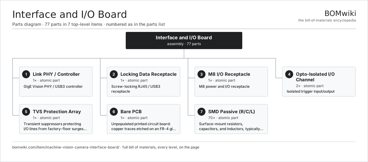
| # | Part | Qty | What it does |
|---|---|---|---|
| 1 | Link PHY / Controller | 1× | GigE Vision PHY / USB3 controller |
| 2 | Locking Data Receptacle | 1× | Screw-locking RJ45 / USB3 receptacle |
| 3 | M8 I/O Receptacle | 1× | M8 power and I/O receptacle |
| 4 | Opto-Isolated I/O Channel | 2× | Isolated trigger input/output |
| 5 | TVS Protection Array | 1× | Transient suppressors protecting I/O lines from factory-floor surges and ESD. |
| 6 | Bare PCB | 1× | Unpopulated printed circuit board: copper traces etched on an FR-4 glass-epoxy laminate that carry current between the components later soldered to it. |
| 7 | SMD Passive (R/C/L) | 70× | Surface-mount resistors, capacitors, and inductors, typically in 0402 to 1206 packages, that set voltages, filter noise, and time signals on a circuit board. |
3D model
No 3D model yet. Have a CAD file of this? Add a 3D model. STL renders right on this page; STEP, FreeCAD, and OpenSCAD sources are welcome too (openly licensed, like all 3D models on BOMwiki).
Build & assembly graph
expand / collapse · shared sub-assemblies converge · links to related products · est. labour
product / assembly
shared across products
atomic part
related product
Tap an assembly to expand/collapse · tap a part to open it · use “Open page” for any node · drag to pan, scroll to zoom.
Bill of materials for Interface and I/O Board
7 top-level lines · 7 rows shown · 77 parts total · indented to 3 levels| # | Item / sub-assembly | Part no. | Qty/assy | Ext. qty | Parts | Type |
|---|---|---|---|---|---|---|
| 1 | Link PHY / Controller | machine-vision-camera-phy | 1× | 1 | · | part |
| 2 | Locking Data Receptacle | machine-vision-camera-rj45 | 1× | 1 | · | part |
| 3 | M8 I/O Receptacle | machine-vision-camera-m8-io | 1× | 1 | · | part |
| 4 | Opto-Isolated I/O Channel | machine-vision-camera-optocoupler | 2× | 2 | · | part |
| 5 | TVS Protection Array | machine-vision-camera-tvs-array | 1× | 1 | · | part |
| 6 | Bare PCB | pcb-bare | 1× | 1 | · | part |
| 7 | SMD Passive (R/C/L) | smd-passives | 70× | 70 | · | part |
Something wrong in this list? Report a problem with this BOM.
Where the interface and I/O board is used
1 product across 1 domain contain it, directly or inside a sub-assemblyUsed in 1 assembly
Sourcing: possible vendors
Browse the supplier directory → Prices, MOQ, and lead times are algorithmic estimates, not quotes, and not claims about these companies. Company mappings are curated by keyword; est. price band $1–$200. How estimates work| Vendor | HQ | Specialty | MOQ | Lead time |
|---|---|---|---|---|
|
🇨🇳JLCPCB
jlcpcb.com ↗
|
Shenzhen, CN | PCB fabrication | 100 pcs | 2–4 wks |
|
🇨🇳PCBWay
pcbway.com ↗
|
Shenzhen, CN | PCB fab & assembly | 100 pcs | 2–4 wks |
| scc.com.cn ↗ | Shenzhen, CN | PCB manufacturer | 100 pcs | 2–4 wks |
| shogini.com ↗ | Mumbai, IN | PCB manufacturer | 100 pcs | 2–4 wks |
| venture.com.sg ↗ | Singapore | Electronics contract mfg | 100 pcs | 2–4 wks |