Industrial 3D Scanner
ProductOverview
An industrial 3D scanner captures the surface of a physical part as a dense cloud of measured 3D points, usually millions of them, and turns that cloud into a polygon mesh. Manufacturers use it to check whether a machined or molded part matches its CAD model, to digitize a part that has no drawing, and to inspect tooling and castings. This scanner uses structured light: it projects a known pattern of stripes onto the part and watches how the surface bends that pattern. Because the geometry between the projector and the cameras is fixed and known, the bending of each stripe encodes the depth at every pixel.
The machine is built around eight subsystems. The Fringe Projector Unit casts the stripe patterns. The Stereo Camera Pair records how the part deforms them. The Sensor Head Frame holds the projector and cameras in a rigid, temperature-stable frame. The Processing Computer turns raw images into a point cloud and mesh. The Rotary and Tilt Stage indexes the part through a set of poses for automated capture. The Calibration Kit holds the certified artifacts that set and verify accuracy. The Stand and Robot Interface positions the head on a tripod or a robot. The Trigger and Sync Board triggers the projector and both cameras in lockstep.
How it works
The Blue LED Light Engine sends 460 nm blue light through the DMD Projection Chip, a grid of about two million tiny mirrors. The chip switches the mirrors to draw a sinusoidal stripe pattern, and the Telecentric Projection Lens focuses it onto the part. The projector shows a timed sequence of patterns, each shifted in phase, while the Industrial CMOS Camera pair records every frame through the Blue Bandpass Filter that blocks room light.
Software then runs phase shifting. For each camera pixel it reads the brightness across the pattern sequence and computes the phase of the stripe falling on that point. Phase maps directly to a line of sight from the projector. Combining that with the two camera views, each looking from a slightly different angle through the Machine Vision Lens, gives three rays that intersect at one surface point. Doing this for every pixel produces millions of points. The GPU Compute Board runs this per-pixel math in parallel, which is why a full frame finishes in well under a second.
Why the frame and calibration matter
Triangulation only works if the angle between projector and cameras stays exactly as calibrated. A shift of a few microns throws off accuracy across the whole field. The Invar Baseplate is machined from Invar 36, an alloy whose length barely changes with temperature, so the optics hold their geometry from a cold morning to a warm afternoon on the shop floor. The Frame Temperature Sensor readings feed a compensation model that trims the remaining drift.
Calibration uses the Calibration Plate, a ceramic plate with chrome dots at certified spacing. The scanner measures it from many angles, and the solver works back to the lens distortion and the projector-to-camera geometry. The Reference Sphere bars then verify the result: the scanner measures a known sphere diameter and center distance, and any error shows the calibration has drifted.
Materials and construction
The sensor head splits into a precision core and a protective shell. The core is the Invar baseplate carrying ceramic and glass optics. The Sensor Head Cover is formed sheet metal with a matte black interior to kill stray reflections, sealed by the Front Optical Window up front. Heat is the enemy of stability, so the LED Heatsink and the Housing Cooling Fan hold temperatures steady while a Servo Motor drives each axis of the Precision Rotary Table through hardened Helical Gear Pair sets on Ball Bearing supports.
Automation and variants
For one-off parts the head sits on the Machine Vision Tripod and the operator runs scans from the Operator Panel. For repeat work the part goes on the rotary and tilt stage, which steps it through poses logged by the Axis Encoder so partial scans register cleanly into one model. For inline inspection the head bolts to a robot through the Robot Mounting Flange. Variants differ mainly by field of view: a 100 mm setup reaches the finest point spacing for small machined parts, while a 500 mm setup covers castings and body panels at coarser resolution.
Use in measurement
This scanner sits alongside contact metrology rather than replacing it. A Coordinate Measuring Machine probes a few precise points and is the reference for tight tolerances, while the 3D scanner gives a dense surface map in seconds and catches form errors a probe would miss between points. On very large structures a Laser Tracker establishes a global frame, and scan patches from this machine fill in surface detail. Typical jobs are first-article inspection of machined parts, wear measurement on tooling and dies, reverse engineering of legacy parts into CAD, and comparing a production part against its nominal model with a color deviation map.
Industrial 3D Scanner parts and their functions
8 top-level parts · 149 parts in total · full bill of materials below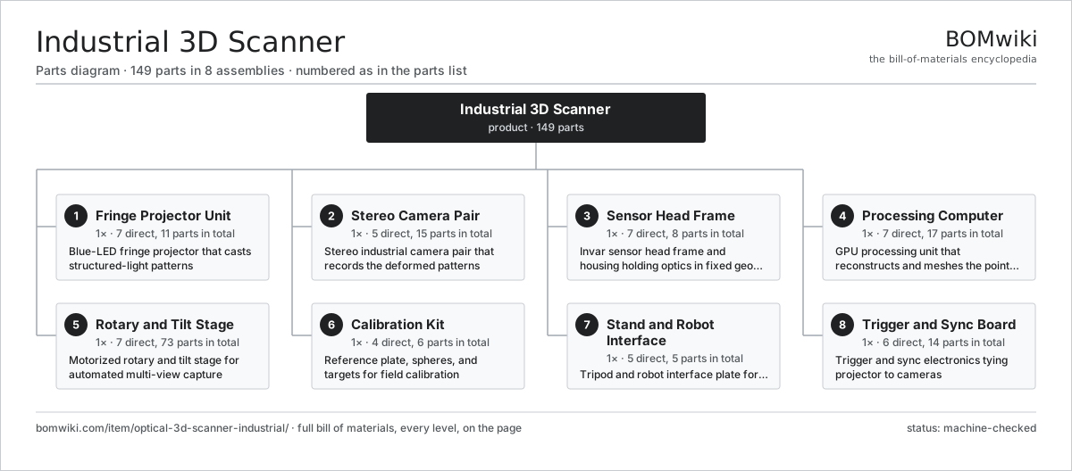
| # | Part | Qty | What it does |
|---|---|---|---|
| 1 | Fringe Projector Unit 7 parts | 1× | Blue-LED fringe projector that casts structured-light patterns |
| 2 | Stereo Camera Pair 5 parts | 1× | Stereo industrial camera pair that records the deformed patterns |
| 3 | Sensor Head Frame 7 parts | 1× | Invar sensor head frame and housing holding optics in fixed geometry |
| 4 | Processing Computer 7 parts | 1× | GPU processing unit that reconstructs and meshes the point cloud |
| 5 | Rotary and Tilt Stage 7 parts | 1× | Motorized rotary and tilt stage for automated multi-view capture |
| 6 | Calibration Kit 4 parts | 1× | Reference plate, spheres, and targets for field calibration |
| 7 | Stand and Robot Interface 5 parts | 1× | Tripod and robot interface plate for positioning the head |
| 8 | Trigger and Sync Board 6 parts | 1× | Trigger and sync electronics tying projector to cameras |
3D model
No 3D model yet. Have a CAD file of this? Add a 3D model — STL renders right on this page; STEP, FreeCAD, and OpenSCAD sources are welcome too (openly licensed, like all 3D models on BOMwiki).
Build & assembly graph
expand / collapse · shared sub-assemblies converge · links to related products · est. labourTap an assembly to expand/collapse · tap a part to open it · use “Open page” for any node · drag to pan, scroll to zoom.
Bill of materials for Industrial 3D Scanner
8 top-level lines · 92 rows shown · 149 parts total · indented to 3 levels| # | Item / sub-assembly | Part no. | Qty/assy | Ext. qty | Parts | Type |
|---|---|---|---|---|---|---|
| 1 | Fringe Projector Unit 7 parts | optical-3d-scanner-industrial-projector-unit | 1× | 1 | 11 | assembly |
| 1.1 | Blue LED Light Engine | optical-3d-scanner-industrial-led-engine | 1× | 1 | · | part |
| 1.2 | DMD Projection Chip | optical-3d-scanner-industrial-dmd-chip | 1× | 1 | · | part |
| 1.3 | Telecentric Projection Lens | optical-3d-scanner-industrial-projection-lens | 1× | 1 | · | part |
| 1.4 | Projector Driver Board 4 parts | optical-3d-scanner-industrial-projector-driver | 1× | 1 | 5 | assembly |
| 1.4.1 | Bare PCB | pcb-bare | 1× | 1 | · | part |
| 1.4.2 | Microcontroller | mcu | 1× | 1 | · | part |
| 1.4.3 | SMD Passive (R/C/L) | smd-passives | 1× | 1 | · | part |
| 1.4.4 | Connector | connector | 2× | 2 | · | part |
| 1.5 | LED Heatsink | optical-3d-scanner-industrial-led-heatsink | 1× | 1 | · | part |
| 1.6 | O-Ring Set | oring-set | 1× | 1 | · | part |
| 1.7 | Fastener Set | fastener-set | 1× | 1 | · | part |
| 2 | Stereo Camera Pair 5 parts | optical-3d-scanner-industrial-camera-pair | 1× | 1 | 15 | assembly |
| 2.1 | Industrial CMOS Camera 4 parts | optical-3d-scanner-industrial-camera-module | 2× | 2 | 4 | assembly |
| 2.1.1 | 12 MP CMOS Image Sensor | optical-3d-scanner-industrial-cmos-sensor | 1× | 2 | · | part |
| 2.1.2 | Bare PCB | pcb-bare | 1× | 2 | · | part |
| 2.1.3 | SMD Passive (R/C/L) | smd-passives | 1× | 2 | · | part |
| 2.1.4 | Connector | connector | 1× | 2 | · | part |
| 2.2 | Machine Vision Lens | optical-3d-scanner-industrial-camera-lens | 2× | 2 | · | part |
| 2.3 | Convergence Mount | optical-3d-scanner-industrial-camera-mount | 2× | 2 | · | part |
| 2.4 | Blue Bandpass Filter | optical-3d-scanner-industrial-bandpass-filter | 2× | 2 | · | part |
| 2.5 | Fastener Set | fastener-set | 1× | 1 | · | part |
| 3 | Sensor Head Frame 7 parts | optical-3d-scanner-industrial-sensor-head | 1× | 1 | 8 | assembly |
| 3.1 | Invar Baseplate | optical-3d-scanner-industrial-invar-baseplate | 1× | 1 | · | part |
| 3.2 | Sensor Head Cover | optical-3d-scanner-industrial-head-cover | 1× | 1 | · | part |
| 3.3 | Front Optical Window | optical-3d-scanner-industrial-optical-window | 1× | 1 | · | part |
| 3.4 | Frame Temperature Sensor | optical-3d-scanner-industrial-temp-sensor | 2× | 2 | · | part |
| 3.5 | Housing Cooling Fan | optical-3d-scanner-industrial-cooling-fan | 1× | 1 | · | part |
| 3.6 | O-Ring Set | oring-set | 1× | 1 | · | part |
| 3.7 | Fastener Set | fastener-set | 1× | 1 | · | part |
| 4 | Processing Computer 7 parts | optical-3d-scanner-industrial-compute-unit | 1× | 1 | 17 | assembly |
| 4.1 | GPU Compute Board 3 parts | optical-3d-scanner-industrial-gpu-board | 1× | 1 | 4 | assembly |
| 4.1.1 | Bare PCB | pcb-bare | 1× | 1 | · | part |
| 4.1.2 | SMD Passive (R/C/L) | smd-passives | 1× | 1 | · | part |
| 4.1.3 | Connector | connector | 2× | 2 | · | part |
| 4.2 | Host Mainboard 4 parts | optical-3d-scanner-industrial-mainboard | 1× | 1 | 7 | assembly |
| 4.2.1 | Bare PCB | pcb-bare | 1× | 1 | · | part |
| 4.2.2 | Microcontroller | mcu | 1× | 1 | · | part |
| 4.2.3 | SMD Passive (R/C/L) | smd-passives | 1× | 1 | · | part |
| 4.2.4 | Connector | connector | 4× | 4 | · | part |
| 4.3 | Power Supply | power-supply | 1× | 1 | · | part |
| 4.4 | NVMe Scan Storage | optical-3d-scanner-industrial-storage | 1× | 1 | · | part |
| 4.5 | Frame Grabber Board | optical-3d-scanner-industrial-frame-grabber | 1× | 1 | · | part |
| 4.6 | Chassis Cooling Fan | optical-3d-scanner-industrial-compute-fan | 2× | 2 | · | part |
| 4.7 | Wire Bundle | wire-bundle | 1× | 1 | · | part |
| 5 | Rotary and Tilt Stage 7 parts | optical-3d-scanner-industrial-rotary-stage | 1× | 1 | 73 | assembly |
| 5.1 | Precision Rotary Table 4 parts | optical-3d-scanner-industrial-rotary-table | 1× | 1 | 5 | assembly |
| 5.1.1 | Turntable Platter | optical-3d-scanner-industrial-table-platter | 1× | 1 | · | part |
| 5.1.2 | Ball Bearing | ball-bearing | 2× | 2 | · | part |
| 5.1.3 | Helical Gear Pair | gear-pair | 1× | 1 | · | part |
| 5.1.4 | Fastener Set | fastener-set | 1× | 1 | · | part |
| 5.2 | Tilt Axis Assembly 3 parts | optical-3d-scanner-industrial-tilt-axis | 1× | 1 | 4 | assembly |
| 5.2.1 | Tilt Cradle | optical-3d-scanner-industrial-tilt-cradle | 1× | 1 | · | part |
| 5.2.2 | Ball Bearing | ball-bearing | 2× | 2 | · | part |
| 5.2.3 | Helical Gear Pair | gear-pair | 1× | 1 | · | part |
| 5.3 | Servo Motor 4 parts | servo-motor | 2× | 2 | 24 | assembly |
| 5.3.1 | Stator Assembly 3 parts + deeper › | stator-assembly | 1× | 2 | 3 | assembly |
| 5.3.2 | Rotor Assembly 4 parts + deeper › | rotor-assembly | 1× | 2 | 19 | assembly |
| 5.3.3 | Encoder | encoder | 1× | 2 | · | part |
| 5.3.4 | Motor Housing | motor-housing | 1× | 2 | · | part |
| 5.4 | Helical Gear Pair | gear-pair | 2× | 2 | · | part |
| 5.5 | Ball Bearing | ball-bearing | 4× | 4 | · | part |
| 5.6 | Axis Encoder | optical-3d-scanner-industrial-encoder | 2× | 2 | · | part |
| 5.7 | Stage Motion Board 5 parts | optical-3d-scanner-industrial-stage-driver | 1× | 1 | 8 | assembly |
| 5.7.1 | Bare PCB | pcb-bare | 1× | 1 | · | part |
| 5.7.2 | Microcontroller | mcu | 1× | 1 | · | part |
| 5.7.3 | SMD Passive (R/C/L) | smd-passives | 1× | 1 | · | part |
| 5.7.4 | Relay | relay | 2× | 2 | · | part |
| 5.7.5 | Connector | connector | 3× | 3 | · | part |
| 6 | Calibration Kit 4 parts | optical-3d-scanner-industrial-calibration-kit | 1× | 1 | 6 | assembly |
| 6.1 | Calibration Plate | optical-3d-scanner-industrial-cal-plate | 1× | 1 | · | part |
| 6.2 | Reference Sphere | optical-3d-scanner-industrial-reference-sphere | 3× | 3 | · | part |
| 6.3 | Photogrammetry Targets | optical-3d-scanner-industrial-photo-targets | 1× | 1 | · | part |
| 6.4 | Calibration Case | optical-3d-scanner-industrial-cal-case | 1× | 1 | · | part |
| 7 | Stand and Robot Interface 5 parts | optical-3d-scanner-industrial-stand | 1× | 1 | 5 | assembly |
| 7.1 | Machine Vision Tripod | optical-3d-scanner-industrial-tripod | 1× | 1 | · | part |
| 7.2 | Pan and Tilt Head | optical-3d-scanner-industrial-pan-tilt-head | 1× | 1 | · | part |
| 7.3 | Robot Mounting Flange | optical-3d-scanner-industrial-robot-flange | 1× | 1 | · | part |
| 7.4 | Quick-Release Plate | optical-3d-scanner-industrial-quick-mount | 1× | 1 | · | part |
| 7.5 | Fastener Set | fastener-set | 1× | 1 | · | part |
| 8 | Trigger and Sync Board 6 parts | optical-3d-scanner-industrial-control-board | 1× | 1 | 14 | assembly |
| 8.1 | Bare PCB | pcb-bare | 1× | 1 | · | part |
| 8.2 | Microcontroller | mcu | 1× | 1 | · | part |
| 8.3 | SMD Passive (R/C/L) | smd-passives | 1× | 1 | · | part |
| 8.4 | Connector | connector | 4× | 4 | · | part |
| 8.5 | Wire Bundle | wire-bundle | 1× | 1 | · | part |
| 8.6 | Operator Panel 5 parts | optical-3d-scanner-industrial-operator-panel | 1× | 1 | 6 | assembly |
| 8.6.1 | LCD Panel | lcd-panel | 1× | 1 | · | part |
| 8.6.2 | Bare PCB | pcb-bare | 1× | 1 | · | part |
| 8.6.3 | SMD Passive (R/C/L) | smd-passives | 1× | 1 | · | part |
| 8.6.4 | Connector | connector | 2× | 2 | · | part |
| 8.6.5 | Sheet Metal Panel | sheet-panel | 1× | 1 | · | part |
Related products
same domain, ranked by shared parts Slide Projector
182 parts · shares 19 with this page
Slide Projector
182 parts · shares 19 with this page
 Digital Cinema Projector
383 parts · shares 18 with this page
Digital Cinema Projector
383 parts · shares 18 with this page
 Photo Minilab
454 parts · shares 17 with this page
Photo Minilab
454 parts · shares 17 with this page
 Laser Tracker
142 parts · shares 18 with this page
Laser Tracker
142 parts · shares 18 with this page
 Microfilm Scanner
348 parts · shares 17 with this page
Terrestrial Laser Scanner
570 parts · shares 16 with this page
Microfilm Scanner
348 parts · shares 17 with this page
Terrestrial Laser Scanner
570 parts · shares 16 with this page
Sourcing: possible vendors
Prices, MOQ, and lead times are algorithmic estimates, not quotes, and not claims about these companies. Company mappings are curated by keyword; est. price band $100–$8k. How estimates work| Vendor | HQ | Specialty | MOQ | Lead time |
|---|---|---|---|---|
|
🇯🇵Canon
canon.com ↗
|
Tokyo, JP | Imaging & optics | 500 units | 10–16 wks |
|
🇯🇵Nikon
nikon.com ↗
|
Tokyo, JP | Imaging & optics | 500 units | 10–16 wks |
|
🇩🇪ZEISS
zeiss.com ↗
|
Oberkochen, DE | Optics & optoelectronics | 500 units | 10–16 wks |
| leica-camera.com ↗ | Wetzlar, DE | Cameras & optics | 500 units | 10–16 wks |
| flir.com ↗ | Wilsonville, US | Thermal imaging | 500 units | 10–16 wks |
918-word article