Laser Tracker
ProductOverview
A laser tracker measures the position of points on large objects by aiming a laser beam at a moving reflective target and reading both the direction the beam points and the distance it travels. The instrument reports each point in spherical coordinates: two angles and one range, which it converts into Cartesian XYZ. The angles come from the Angle Encoder System, the range from the Laser Distance Unit, and the Position-Sensitive Tracking Unit keeps the beam locked on the target while it moves. The Beam-Steering Gimbal Head does the physical aiming, the Environment Compensation Unit corrects for the air the beam passes through, and the Controller and Processing Electronics combines everything into a measured coordinate. The operator works with a Retroreflector Target Set, and the whole instrument sits on an Instrument Stand and Mount inside a sealed Housing and Covers.
The reason a laser tracker exists is reach. A bridge-type CMM measures parts that fit on its table; a tracker measures things that do not move to a machine, like aircraft wings, ship sections, machine tool beds, and antenna dishes. One person walks a reflector over the part while the tracker follows.
Measuring distance
The Laser Distance Unit uses two methods at once. The HeNe Laser Source feeds an interferometer: the beam splits at a Beam Splitter into a measurement path and a Reference Path Optics, and the Interferometer Detector counts interference fringes as the target moves. Fringe counting gives sub-micrometre resolution, but it only measures change, not absolute distance, so if the beam is broken the count is lost.
That is why the Absolute Distance Meter sits alongside it. The absolute distance meter reads the full range directly by timing a modulated diode beam, so the system can re-acquire a target and know how far away it is without returning to a home position. The optics ride on a low-expansion Optical Bench Plate in Fiber Coupler connected paths, and a Quarter-Wave Plate manages polarization so the outgoing and returning beams stay separate. The standard target is a Spherically Mounted Retroreflector, a corner cube set in a steel ball whose optical centre coincides with the centre of the sphere, so the reading does not change as the operator rotates it in a nest.
Aiming and tracking
The Beam-Steering Gimbal Head points the beam on two axes. The Azimuth Axis Assembly swings the head horizontally and the Elevation Axis Assembly tilts it vertically, each driven by a direct-drive torque Servo Motor running on precision Ball Bearing spindles. A Steering Mirror folds the beam out through the Exit Window, and a Slip Ring carries power and signals across the azimuth axis so it can rotate without a cable limit.
Tracking is what makes the instrument follow a moving target. Part of the returned beam falls on the Position-Sensitive Detector through the Tracking Lens. When the target moves, the spot drifts off centre, the Detector Amplifier Board turns that offset into a position signal, and the Tracking Servo Board commands the two motors to re-centre it. The loop runs fast enough that an operator can walk a reflector at normal speed and the beam stays locked.
Reading angle
Distance is only half of a coordinate; the other half is direction. The Angle Encoder System reads both axes with glass Encoder Disc scales and paired Read Head units. Two heads per axis sit opposite each other so that any eccentricity of the disc averages out, which is the dominant systematic error in a rotary encoder. The Encoder Interpolation Board interpolates the analog read-head signals into fine angle counts. Because the angular term is multiplied by the range, a small angle error becomes a large position error far from the tracker, so the angular specification is quoted per metre.
Correcting for the air
A laser measures distance in wavelengths, and the wavelength of light depends on the air it travels through. The Environment Compensation Unit measures the conditions that change it: a Air Temperature Probe for air temperature, a Pressure Sensor for barometric pressure, and a Humidity Sensor for moisture. The Environment Sensor Board computes the refractive index of air and scales the raw distance accordingly. A separate Material Temperature Probe reads the temperature of the part itself, so a measurement taken on a warm shop floor can be reported as it would be at 20 degrees C. Without these corrections the distance reading drifts by several micrometres per metre as the weather changes.
Electronics, targets, and support
The Controller and Processing Electronics ties the subsystems together. The Main Processor Board fuses angle, distance, and environment data into a point; the Communications Board sends it to the measurement PC over Ethernet or wireless; the Power Supply and Battery Pack let the instrument run on site. The Retroreflector Target Set gives the operator a choice of reflectors: an Spherically Mounted Retroreflector for general use, a bare Corner-Cube Prism for fixed points, and Magnetic Target Nest seats that hold the ball at a repeatable position. The Instrument Stand and Mount holds the head steady, since any drift of the Heavy Tripod shows up directly in the data, and the Housing and Covers keeps shop dust off the optics.
Use and variants
Laser trackers are used in aircraft and ship assembly, machine tool alignment, antenna and telescope setup, and any task where the part is too large for a room CMM such as a Coordinate Measuring Machine. Where a CMM brings the part to a fixed machine, the tracker is carried to the part. Some trackers add a 6DoF camera probe that reads the orientation of a hand-held stylus, so an operator can probe hidden features and edges that a plain reflector cannot reach. Accuracy in the field depends as much on stable setup and good environment compensation as on the instrument itself.
Laser Tracker parts and their functions
9 top-level parts · 142 parts in total · full bill of materials below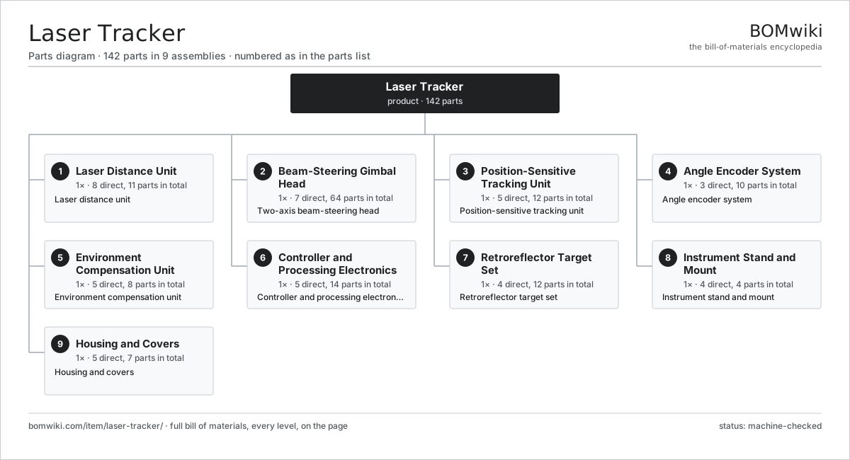
| # | Part | Qty | What it does |
|---|---|---|---|
| 1 | Laser Distance Unit 8 parts | 1× | Laser distance unit |
| 2 | Beam-Steering Gimbal Head 7 parts | 1× | Two-axis beam-steering head |
| 3 | Position-Sensitive Tracking Unit 5 parts | 1× | Position-sensitive tracking unit |
| 4 | Angle Encoder System 3 parts | 1× | Angle encoder system |
| 5 | Environment Compensation Unit 5 parts | 1× | Environment compensation unit |
| 6 | Controller and Processing Electronics 5 parts | 1× | Controller and processing electronics |
| 7 | Retroreflector Target Set 4 parts | 1× | Retroreflector target set |
| 8 | Instrument Stand and Mount 4 parts | 1× | Instrument stand and mount |
| 9 | Housing and Covers 5 parts | 1× | Housing and covers |
3D model
No 3D model yet. Have a CAD file of this? Add a 3D model — STL renders right on this page; STEP, FreeCAD, and OpenSCAD sources are welcome too (openly licensed, like all 3D models on BOMwiki).
Build & assembly graph
expand / collapse · shared sub-assemblies converge · links to related products · est. labourTap an assembly to expand/collapse · tap a part to open it · use “Open page” for any node · drag to pan, scroll to zoom.
Bill of materials for Laser Tracker
9 top-level lines · 84 rows shown · 142 parts total · indented to 3 levels| # | Item / sub-assembly | Part no. | Qty/assy | Ext. qty | Parts | Type |
|---|---|---|---|---|---|---|
| 1 | Laser Distance Unit 8 parts | laser-tracker-distance-unit | 1× | 1 | 11 | assembly |
| 1.1 | HeNe Laser Source | laser-tracker-hene-source | 1× | 1 | · | part |
| 1.2 | Absolute Distance Meter | laser-tracker-adm-module | 1× | 1 | · | part |
| 1.3 | Beam Splitter | laser-tracker-beam-splitter | 3× | 3 | · | part |
| 1.4 | Interferometer Detector | laser-tracker-ifm-detector | 1× | 1 | · | part |
| 1.5 | Reference Path Optics | laser-tracker-reference-arm | 1× | 1 | · | part |
| 1.6 | Fiber Coupler | laser-tracker-fiber-coupler | 2× | 2 | · | part |
| 1.7 | Optical Bench Plate | laser-tracker-optical-bench | 1× | 1 | · | part |
| 1.8 | Quarter-Wave Plate | laser-tracker-quarter-wave-plate | 1× | 1 | · | part |
| 2 | Beam-Steering Gimbal Head 7 parts | laser-tracker-gimbal-head | 1× | 1 | 64 | assembly |
| 2.1 | Azimuth Axis Assembly 4 parts | laser-tracker-azimuth-axis | 1× | 1 | 28 | assembly |
| 2.1.1 | Azimuth Spindle | laser-tracker-azimuth-spindle | 1× | 1 | · | part |
| 2.1.2 | Servo Motor 4 parts + deeper › | servo-motor | 1× | 1 | 24 | assembly |
| 2.1.3 | Ball Bearing | ball-bearing | 2× | 2 | · | part |
| 2.1.4 | Axis Housing | laser-tracker-axis-housing | 1× | 1 | · | part |
| 2.2 | Elevation Axis Assembly 4 parts | laser-tracker-elevation-axis | 1× | 1 | 28 | assembly |
| 2.2.1 | Elevation Spindle | laser-tracker-elevation-spindle | 1× | 1 | · | part |
| 2.2.2 | Servo Motor 4 parts + deeper › | servo-motor | 1× | 1 | 24 | assembly |
| 2.2.3 | Ball Bearing | ball-bearing | 2× | 2 | · | part |
| 2.2.4 | Elevation Yoke | laser-tracker-yoke | 1× | 1 | · | part |
| 2.3 | Steering Mirror | laser-tracker-steering-mirror | 1× | 1 | · | part |
| 2.4 | Exit Window | laser-tracker-exit-window | 1× | 1 | · | part |
| 2.5 | Mirror Mount | laser-tracker-mirror-mount | 1× | 1 | · | part |
| 2.6 | Slip Ring | laser-tracker-slip-ring | 1× | 1 | · | part |
| 2.7 | Ball Bearing | ball-bearing | 4× | 4 | · | part |
| 3 | Position-Sensitive Tracking Unit 5 parts | laser-tracker-tracking-detector | 1× | 1 | 12 | assembly |
| 3.1 | Position-Sensitive Detector | laser-tracker-psd-sensor | 1× | 1 | · | part |
| 3.2 | Detector Amplifier Board 3 parts | laser-tracker-psd-board | 1× | 1 | 3 | assembly |
| 3.2.1 | Bare PCB | pcb-bare | 1× | 1 | · | part |
| 3.2.2 | SMD Passive (R/C/L) | smd-passives | 1× | 1 | · | part |
| 3.2.3 | Connector | connector | 1× | 1 | · | part |
| 3.3 | Tracking Lens | laser-tracker-tracking-lens | 1× | 1 | · | part |
| 3.4 | Tracking Servo Board 4 parts | laser-tracker-servo-board | 1× | 1 | 5 | assembly |
| 3.4.1 | Bare PCB | pcb-bare | 1× | 1 | · | part |
| 3.4.2 | Microcontroller | mcu | 1× | 1 | · | part |
| 3.4.3 | SMD Passive (R/C/L) | smd-passives | 1× | 1 | · | part |
| 3.4.4 | Connector | connector | 2× | 2 | · | part |
| 3.5 | Connector | connector | 2× | 2 | · | part |
| 4 | Angle Encoder System 3 parts | laser-tracker-encoder-system | 1× | 1 | 10 | assembly |
| 4.1 | Encoder Disc | laser-tracker-encoder-disc | 2× | 2 | · | part |
| 4.2 | Read Head | laser-tracker-read-head | 4× | 4 | · | part |
| 4.3 | Encoder Interpolation Board 3 parts | laser-tracker-encoder-board | 1× | 1 | 4 | assembly |
| 4.3.1 | Bare PCB | pcb-bare | 1× | 1 | · | part |
| 4.3.2 | SMD Passive (R/C/L) | smd-passives | 1× | 1 | · | part |
| 4.3.3 | Connector | connector | 2× | 2 | · | part |
| 5 | Environment Compensation Unit 5 parts | laser-tracker-environment-unit | 1× | 1 | 8 | assembly |
| 5.1 | Air Temperature Probe | laser-tracker-temp-probe | 1× | 1 | · | part |
| 5.2 | Pressure Sensor | pressure-sensor | 1× | 1 | · | part |
| 5.3 | Humidity Sensor | laser-tracker-humidity-sensor | 1× | 1 | · | part |
| 5.4 | Material Temperature Probe | laser-tracker-material-probe | 1× | 1 | · | part |
| 5.5 | Environment Sensor Board 4 parts | laser-tracker-env-board | 1× | 1 | 4 | assembly |
| 5.5.1 | Bare PCB | pcb-bare | 1× | 1 | · | part |
| 5.5.2 | Microcontroller | mcu | 1× | 1 | · | part |
| 5.5.3 | SMD Passive (R/C/L) | smd-passives | 1× | 1 | · | part |
| 5.5.4 | Connector | connector | 1× | 1 | · | part |
| 6 | Controller and Processing Electronics 5 parts | laser-tracker-controller | 1× | 1 | 14 | assembly |
| 6.1 | Main Processor Board 4 parts | laser-tracker-main-board | 1× | 1 | 7 | assembly |
| 6.1.1 | Bare PCB | pcb-bare | 1× | 1 | · | part |
| 6.1.2 | Microcontroller | mcu | 1× | 1 | · | part |
| 6.1.3 | SMD Passive (R/C/L) | smd-passives | 1× | 1 | · | part |
| 6.1.4 | Connector | connector | 4× | 4 | · | part |
| 6.2 | Power Supply | power-supply | 1× | 1 | · | part |
| 6.3 | Communications Board 3 parts | laser-tracker-comms-board | 1× | 1 | 4 | assembly |
| 6.3.1 | Bare PCB | pcb-bare | 1× | 1 | · | part |
| 6.3.2 | SMD Passive (R/C/L) | smd-passives | 1× | 1 | · | part |
| 6.3.3 | Connector | connector | 2× | 2 | · | part |
| 6.4 | Battery Pack | laser-tracker-battery-pack | 1× | 1 | · | part |
| 6.5 | Wire Bundle | wire-bundle | 1× | 1 | · | part |
| 7 | Retroreflector Target Set 4 parts | laser-tracker-target-set | 1× | 1 | 12 | assembly |
| 7.1 | Spherically Mounted Retroreflector | laser-tracker-smr | 3× | 3 | · | part |
| 7.2 | Corner-Cube Prism | laser-tracker-corner-cube | 3× | 3 | · | part |
| 7.3 | Magnetic Target Nest | laser-tracker-target-nest | 5× | 5 | · | part |
| 7.4 | Target Carry Case | laser-tracker-target-case | 1× | 1 | · | part |
| 8 | Instrument Stand and Mount 4 parts | laser-tracker-stand | 1× | 1 | 4 | assembly |
| 8.1 | Heavy Tripod | laser-tracker-tripod | 1× | 1 | · | part |
| 8.2 | Instrument Mount Interface | laser-tracker-mount-interface | 1× | 1 | · | part |
| 8.3 | Bull-Eye Level | laser-tracker-level | 1× | 1 | · | part |
| 8.4 | Fastener Set | fastener-set | 1× | 1 | · | part |
| 9 | Housing and Covers 5 parts | laser-tracker-enclosure | 1× | 1 | 7 | assembly |
| 9.1 | Body Shell | laser-tracker-body-shell | 1× | 1 | · | part |
| 9.2 | Sheet Metal Panel | sheet-panel | 2× | 2 | · | part |
| 9.3 | Carry Handle | laser-tracker-carry-handle | 2× | 2 | · | part |
| 9.4 | O-Ring Set | oring-set | 1× | 1 | · | part |
| 9.5 | Fastener Set | fastener-set | 1× | 1 | · | part |
Related products
same domain, ranked by shared parts Photo Minilab
454 parts · shares 17 with this page
Photo Minilab
454 parts · shares 17 with this page
 Industrial 3D Scanner
149 parts · shares 18 with this page
Industrial 3D Scanner
149 parts · shares 18 with this page
 Microfilm Scanner
348 parts · shares 17 with this page
Microfilm Scanner
348 parts · shares 17 with this page
 Slide Projector
182 parts · shares 17 with this page
Slide Projector
182 parts · shares 17 with this page
 Digital Cinema Projector
383 parts · shares 17 with this page
Terrestrial Laser Scanner
570 parts · shares 16 with this page
Digital Cinema Projector
383 parts · shares 17 with this page
Terrestrial Laser Scanner
570 parts · shares 16 with this page
Sourcing: possible vendors
Prices, MOQ, and lead times are algorithmic estimates, not quotes, and not claims about these companies. Company mappings are curated by keyword; est. price band $100–$8k. How estimates work| Vendor | HQ | Specialty | MOQ | Lead time |
|---|---|---|---|---|
|
🇯🇵Canon
canon.com ↗
|
Tokyo, JP | Imaging & optics | 500 units | 10–16 wks |
|
🇯🇵Nikon
nikon.com ↗
|
Tokyo, JP | Imaging & optics | 500 units | 10–16 wks |
|
🇩🇪ZEISS
zeiss.com ↗
|
Oberkochen, DE | Optics & optoelectronics | 500 units | 10–16 wks |
| leica-camera.com ↗ | Wetzlar, DE | Cameras & optics | 500 units | 10–16 wks |
| flir.com ↗ | Wilsonville, US | Thermal imaging | 500 units | 10–16 wks |
1,028-word article