Camera Gimbal Stabilizer
ProductOverview
A camera gimbal stabilizer holds a camera steady against the operator's unwanted motion using three motorised axes. An inertial sensor measures how the camera is moving, and three brushless motors counter-rotate pan, tilt, and roll fast enough to cancel shake, drift, and walking bounce. The result is fluid, tripod-smooth footage from a handheld rig, with the same motors able to execute deliberate moves on command.
How it works
A 6-axis Camera Tray carries the camera and the reference IMU that senses orientation hundreds of times per second. The Main Control Board runs the stabilization loop, comparing the measured orientation against the target and commanding three direct-drive motors: the Pan BLDC Motor for yaw, the Tilt BLDC Motor for pitch, and the Roll BLDC Motor for roll. Each motor carries an absolute magnetic encoder so the controller always knows its joint angle, and hollow shafts with slip rings route power and signal across continuously rotating axes without tangling wires.
The motors are linked by the Pan Arm and roll arm into a nested yoke, so a correction on one axis stays mechanically independent of the others. The operator holds the Handle Grip, an overmoulded grip housing the removable battery and the tripod-thread base, and steers through the Control Board and its joystick, trigger, mode wheel, and touchscreen.
Because the motors must hold the rig in balance with minimum effort, the camera is first mechanically balanced on the dovetail quick-release plate before power-up; well-balanced loads draw little current and run cooler and quieter. A wireless module links to a phone app and to the camera itself for shutter and focus control, and an external focus wheel drives the lens. Combined, these parts turn a shaky handheld shot into a controlled, repeatable camera move.
Camera Gimbal Stabilizer parts and their functions
16 top-level parts · 177 parts in total · full bill of materials below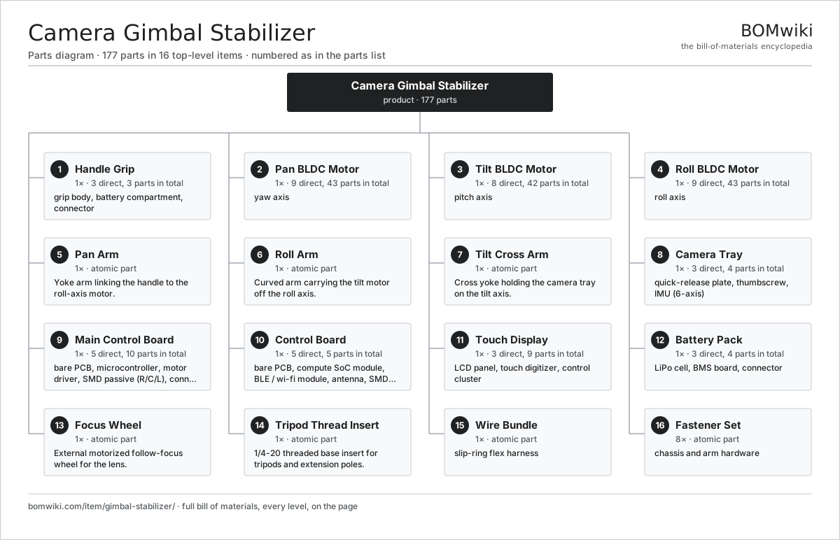
| # | Part | Qty | What it does |
|---|---|---|---|
| 1 | Handle Grip 3 parts | 1× | Ergonomic grip body housing the battery compartment and tripod base. |
| 2 | Pan BLDC Motor 9 parts | 1× | yaw axis |
| 3 | Tilt BLDC Motor 8 parts | 1× | pitch axis |
| 4 | Roll BLDC Motor 9 parts | 1× | roll axis |
| 5 | Pan Arm | 1× | Yoke arm linking the handle to the roll-axis motor. |
| 6 | Roll Arm | 1× | Curved arm carrying the tilt motor off the roll axis. |
| 7 | Tilt Cross Arm | 1× | Cross yoke holding the camera tray on the tilt axis. |
| 8 | Camera Tray 3 parts | 1× | Tilt-axis tray carrying the quick-release plate and the gimbal IMU. |
| 9 | Main Control Board 5 parts | 1× | Motor-drive board running the stabilization loop and driving the three axes. |
| 10 | Control Board 5 parts | 1× | Application board running the UI and wireless link to phone and camera. |
| 11 | Touch Display 3 parts | 1× | Small touchscreen on the handle for status and menu control. |
| 12 | Battery Pack 3 parts | 1× | Removable Li-ion pack powering the gimbal and accessories. |
| 13 | Focus Wheel | 1× | External motorized follow-focus wheel for the lens. |
| 14 | Tripod Thread Insert | 1× | 1/4-20 threaded base insert for tripods and extension poles. |
| 15 | Wire Bundle | 1× | slip-ring flex harness |
| 16 | Fastener Set | 8× | chassis and arm hardware |
3D model
No 3D model yet. Have a CAD file of this? Add a 3D model. STL renders right on this page; STEP, FreeCAD, and OpenSCAD sources are welcome too (openly licensed, like all 3D models on BOMwiki).
Build & assembly graph
expand / collapse · shared sub-assemblies converge · links to related products · est. labourTap an assembly to expand/collapse · tap a part to open it · use “Open page” for any node · drag to pan, scroll to zoom.
Bill of materials for Camera Gimbal Stabilizer
16 top-level lines · 89 rows shown · 177 parts total · indented to 3 levels| # | Item / sub-assembly | Part no. | Qty/assy | Ext. qty | Parts | Type |
|---|---|---|---|---|---|---|
| 1 | Handle Grip 3 parts | gimbal-stabilizer-handle | 1× | 1 | 3 | assembly |
| 1.1 | Grip Body | gimbal-stabilizer-grip-body | 1× | 1 | · | part |
| 1.2 | Battery Compartment | gimbal-stabilizer-battery-compartment | 1× | 1 | · | part |
| 1.3 | Connector | connector | 1× | 1 | · | part |
| 2 | Pan BLDC Motor 9 parts | gimbal-stabilizer-pan-motor | 1× | 1 | 43 | assembly |
| 2.1 | Stator Assembly 3 parts | stator-assembly | 1× | 1 | 3 | assembly |
| 2.1.1 | Stator Core (laminations) | stator-core | 1× | 1 | · | part |
| 2.1.2 | Copper Winding | copper-winding | 1× | 1 | · | part |
| 2.1.3 | Slot Insulation | stator-insulation | 1× | 1 | · | part |
| 2.2 | Rotor Assembly 4 parts | rotor-assembly | 1× | 1 | 19 | assembly |
| 2.2.1 | Rotor Shaft | rotor-shaft | 1× | 1 | · | part |
| 2.2.2 | Rotor Core | rotor-core | 1× | 1 | · | part |
| 2.2.3 | Neodymium Magnet | neodymium-magnet | 16× | 16 | · | part |
| 2.2.4 | Ball Bearing | ball-bearing | 1× | 1 | · | part |
| 2.3 | Copper Winding | copper-winding | 1× | 1 | · | part |
| 2.4 | Neodymium Magnet | neodymium-magnet | 14× | 14 | · | part |
| 2.5 | Ball Bearing | ball-bearing | 2× | 2 | · | part |
| 2.6 | Hollow Shaft | gimbal-stabilizer-hollow-shaft | 1× | 1 | · | part |
| 2.7 | Slip Ring | gimbal-stabilizer-slip-ring | 1× | 1 | · | part |
| 2.8 | Hall Sensor | hall-sensor | 1× | 1 | · | part |
| 2.9 | Magnetic Encoder | gimbal-stabilizer-rotor-encoder | 1× | 1 | · | part |
| 3 | Tilt BLDC Motor 8 parts | gimbal-stabilizer-tilt-motor | 1× | 1 | 42 | assembly |
| 3.1 | Stator Assembly 3 parts | stator-assembly | 1× | 1 | 3 | assembly |
| 3.1.1 | Stator Core (laminations) | stator-core | 1× | 1 | · | part |
| 3.1.2 | Copper Winding | copper-winding | 1× | 1 | · | part |
| 3.1.3 | Slot Insulation | stator-insulation | 1× | 1 | · | part |
| 3.2 | Rotor Assembly 4 parts | rotor-assembly | 1× | 1 | 19 | assembly |
| 3.2.1 | Rotor Shaft | rotor-shaft | 1× | 1 | · | part |
| 3.2.2 | Rotor Core | rotor-core | 1× | 1 | · | part |
| 3.2.3 | Neodymium Magnet | neodymium-magnet | 16× | 16 | · | part |
| 3.2.4 | Ball Bearing | ball-bearing | 1× | 1 | · | part |
| 3.3 | Copper Winding | copper-winding | 1× | 1 | · | part |
| 3.4 | Neodymium Magnet | neodymium-magnet | 14× | 14 | · | part |
| 3.5 | Ball Bearing | ball-bearing | 2× | 2 | · | part |
| 3.6 | Hollow Shaft | gimbal-stabilizer-hollow-shaft | 1× | 1 | · | part |
| 3.7 | Hall Sensor | hall-sensor | 1× | 1 | · | part |
| 3.8 | Magnetic Encoder | gimbal-stabilizer-rotor-encoder | 1× | 1 | · | part |
| 4 | Roll BLDC Motor 9 parts | gimbal-stabilizer-roll-motor | 1× | 1 | 43 | assembly |
| 4.1 | Stator Assembly 3 parts | stator-assembly | 1× | 1 | 3 | assembly |
| 4.1.1 | Stator Core (laminations) | stator-core | 1× | 1 | · | part |
| 4.1.2 | Copper Winding | copper-winding | 1× | 1 | · | part |
| 4.1.3 | Slot Insulation | stator-insulation | 1× | 1 | · | part |
| 4.2 | Rotor Assembly 4 parts | rotor-assembly | 1× | 1 | 19 | assembly |
| 4.2.1 | Rotor Shaft | rotor-shaft | 1× | 1 | · | part |
| 4.2.2 | Rotor Core | rotor-core | 1× | 1 | · | part |
| 4.2.3 | Neodymium Magnet | neodymium-magnet | 16× | 16 | · | part |
| 4.2.4 | Ball Bearing | ball-bearing | 1× | 1 | · | part |
| 4.3 | Copper Winding | copper-winding | 1× | 1 | · | part |
| 4.4 | Neodymium Magnet | neodymium-magnet | 14× | 14 | · | part |
| 4.5 | Ball Bearing | ball-bearing | 2× | 2 | · | part |
| 4.6 | Hollow Shaft | gimbal-stabilizer-hollow-shaft | 1× | 1 | · | part |
| 4.7 | Slip Ring | gimbal-stabilizer-slip-ring | 1× | 1 | · | part |
| 4.8 | Hall Sensor | hall-sensor | 1× | 1 | · | part |
| 4.9 | Magnetic Encoder | gimbal-stabilizer-rotor-encoder | 1× | 1 | · | part |
| 5 | Pan Arm | gimbal-stabilizer-pan-arm | 1× | 1 | · | part |
| 6 | Roll Arm | gimbal-stabilizer-roll-arm | 1× | 1 | · | part |
| 7 | Tilt Cross Arm | gimbal-stabilizer-tilt-cross | 1× | 1 | · | part |
| 8 | Camera Tray 3 parts | gimbal-stabilizer-camera-tray | 1× | 1 | 4 | assembly |
| 8.1 | Quick-Release Plate | gimbal-stabilizer-quick-release-plate | 1× | 1 | · | part |
| 8.2 | Thumbscrew | gimbal-stabilizer-thumbscrew | 2× | 2 | · | part |
| 8.3 | IMU (6-axis) | imu | 1× | 1 | · | part |
| 9 | Main Control Board 5 parts | gimbal-stabilizer-main-board | 1× | 1 | 10 | assembly |
| 9.1 | Bare PCB | pcb-bare | 1× | 1 | · | part |
| 9.2 | Microcontroller | mcu | 1× | 1 | · | part |
| 9.3 | Motor Driver | gimbal-stabilizer-motor-driver | 3× | 3 | · | part |
| 9.4 | SMD Passive (R/C/L) | smd-passives | 1× | 1 | · | part |
| 9.5 | Connector | connector | 4× | 4 | · | part |
| 10 | Control Board 5 parts | gimbal-stabilizer-control-board | 1× | 1 | 5 | assembly |
| 10.1 | Bare PCB | pcb-bare | 1× | 1 | · | part |
| 10.2 | Compute SoC Module | soc-module | 1× | 1 | · | part |
| 10.3 | BLE / Wi-Fi Module | gimbal-stabilizer-wireless-module | 1× | 1 | · | part |
| 10.4 | Antenna | gimbal-stabilizer-antenna | 1× | 1 | · | part |
| 10.5 | SMD Passive (R/C/L) | smd-passives | 1× | 1 | · | part |
| 11 | Touch Display 3 parts | gimbal-stabilizer-display | 1× | 1 | 9 | assembly |
| 11.1 | LCD Panel | lcd-panel | 1× | 1 | · | part |
| 11.2 | Touch Digitizer | touch-digitizer | 1× | 1 | · | part |
| 11.3 | Control Cluster 4 parts | gimbal-stabilizer-control-cluster | 1× | 1 | 7 | assembly |
| 11.3.1 | Joystick | gimbal-stabilizer-joystick | 1× | 1 | · | part |
| 11.3.2 | Push Button | gimbal-stabilizer-button | 4× | 4 | · | part |
| 11.3.3 | Trigger | gimbal-stabilizer-trigger | 1× | 1 | · | part |
| 11.3.4 | Mode Wheel | gimbal-stabilizer-mode-wheel | 1× | 1 | · | part |
| 12 | Battery Pack 3 parts | gimbal-stabilizer-battery | 1× | 1 | 4 | assembly |
| 12.1 | LiPo Cell | lipo-cell | 2× | 2 | · | part |
| 12.2 | BMS Board | bms-board | 1× | 1 | · | part |
| 12.3 | Connector | connector | 1× | 1 | · | part |
| 13 | Focus Wheel | gimbal-stabilizer-focus-wheel | 1× | 1 | · | part |
| 14 | Tripod Thread Insert | gimbal-stabilizer-tripod-thread | 1× | 1 | · | part |
| 15 | Wire Bundle | wire-bundle | 1× | 1 | · | part |
| 16 | Fastener Set | fastener-set | 8× | 8 | · | part |
Something wrong in this list? Report a problem with this BOM.
Related products
same domain, ranked by shared parts DSLR Camera
553 parts · shares 17 with this page
 Action Camera
271 parts · shares 9 with this page
 Digital Microscope
88 parts · shares 15 with this page
Profile Projector
94 parts · shares 15 with this page
 Optical Comparator
94 parts · shares 14 with this page
 Dashcam
221 parts · shares 8 with this page
Sourcing: possible vendors
Browse the supplier directory → Prices, MOQ, and lead times are algorithmic estimates, not quotes, and not claims about these companies. Company mappings are curated by keyword; est. price band $100–$8k. How estimates work| Vendor | HQ | Specialty | MOQ | Lead time |
|---|---|---|---|---|
|
🇯🇵Canon
canon.com ↗
|
Tokyo, JP | Imaging & optics | 500 units | 10–16 wks |
|
🇯🇵Nikon
nikon.com ↗
|
Tokyo, JP | Imaging & optics | 500 units | 10–16 wks |
|
🇩🇪ZEISS
zeiss.com ↗
|
Oberkochen, DE | Optics & optoelectronics | 500 units | 10–16 wks |
| leica-camera.com ↗ | Wetzlar, DE | Cameras & optics | 500 units | 10–16 wks |
| flir.com ↗ | Wilsonville, US | Thermal imaging | 500 units | 10–16 wks |
312-word article