Anhydrous Ammonia Applicator
ProductOverview
An anhydrous ammonia applicator injects pressurized liquid ammonia, the most concentrated nitrogen fertilizer at 82% N, directly into the soil. Ammonia boils at minus 33 degrees Celsius at atmospheric pressure, so it is stored and carried as a liquid under pressure in a nurse tank and must be placed below the surface, where soil moisture binds it before it can flash off as gas. The applicator is a toolbar of knife-equipped row units pulled behind a tractor, with a nurse tank trailing in line to supply the ammonia.
The engineering centers on three things: cutting a clean slot and sealing ammonia into the soil at every row, metering the right nitrogen rate as ground speed varies, and managing a product that is toxic, caustic and stored under pressure. Safety is not an add-on here; it shapes the plumbing, the couplings and the operator equipment.
Toolbar Frame
The Toolbar Frame carries the row units across the field. A heavy Center Toolbar clamps the center units and the hitch, with two folding Wing Section sections on Fold Hinge pivots that bring the machine down to road width. A Gauge Wheel set holds the bar at a constant height so injection depth stays even, and a Transport Wheel set carries the weight on the road. Row units clamp anywhere along the bar with a Fastener Set to match crop row spacing.
Injection Row Unit
Each Injection Row Unit does the actual work. A Coulter disc slices through residue ahead of a hardened Injection Shank that drives a replaceable Knife Point point through the soil to 15-20 cm. The knife carries the delivery tube to its tip, releasing ammonia at depth. Behind it, angled Closing Wheel units press the slot shut so soil moisture traps the nitrogen and little escapes to the air. A Parallel Linkage holds the knife angle constant as the unit rides over contour, a Coil Spring supplies down-pressure, and a Trip Spring lets the shank swing back over a rock then reset without damage.
Ammonia Delivery System
The Ammonia Delivery System system moves ammonia from the nurse tank to every knife. A pressure-rated Supply Hose feeds the toolbar, passing through a Heat Exchanger that keeps the ammonia liquid rather than a froth, because vapor and liquid split unevenly at the manifold. A Distribution Manifold manifold then splits the flow equally to a Delivery Tube for each row, each ending in a Check Valve that stops drip when the unit lifts. A Master Shutoff cuts all flow at the headland and serves as the first emergency stop.
Rate Metering
The Rate Metering System system sets the nitrogen rate. A positive-displacement Metering Pump or a controlled orifice sets flow, measured by an Flow Meter and trimmed by a proportional Rate Valve. A Pressure Sensor and a Pressure Gauge track line pressure for setup and to confirm the heat exchanger is keeping the product liquid. Holding rate accurately matters because ammonia is the cheapest nitrogen per unit but easy to over- or under-apply if metering drifts.
Safety System
The Safety System system reflects ammonia's hazard. A Breakaway Coupling coupling seals both ends if the supply hose is yanked apart, an Excess-Flow Valve excess-flow valve closes automatically if a line ruptures and flow spikes, and a Emergency Water Tank of fresh water lets the operator flush skin or eyes immediately after contact. A Hazard Placard placard marks the hazard for road and yard, and a PPE Box stores the goggles and gloves required to handle the product.
Control, Hydraulics and Hitch
The Rate Control Electronics electronics run variable-rate nitrogen: a Rate Controller on an Microcontroller reads a GNSS Receiver receiver and drives the rate valve from speed and prescription, with the operator working an in-cab In-Cab Terminal over a Wire Bundle harness. The Hydraulic System system folds the wings with a Fold Cylinder pair and raises the bar with a Lift Cylinder pair, plumbed through an Hydraulic Hoses set sealed with an O-Ring Set. The Tractor Hitch couples through a forged Drawbar and Hitch Pin, with a Parking Jack for parking, and the nurse tank trails in line behind the toolbar.
Use and Variants
Ammonia is applied pre-plant in spring or fall, often with a nitrogen stabilizer, and placement depth and slot sealing decide how much stays in the soil. Variants include single-disc low-disturbance openers for no-till fields, strip-till bars that build a fertilized berm for the next crop's row, and sectional shutoff that closes individual rows to avoid double-applying on overlaps. Common options are run-blockage monitoring that alarms if a knife plugs, automatic depth control, and dual-product setups that band dry or liquid starter alongside the ammonia.
Anhydrous Ammonia Applicator parts and their functions
8 top-level parts · 162 parts in total · full bill of materials below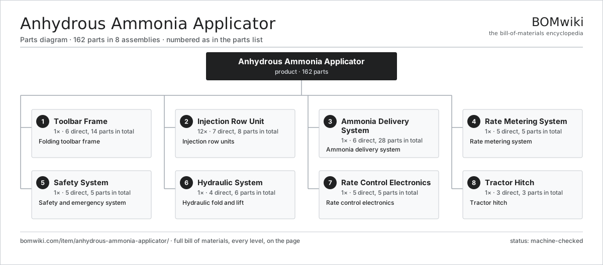
| # | Part | Qty | What it does |
|---|---|---|---|
| 1 | Toolbar Frame 6 parts | 1× | Folding toolbar frame |
| 2 | Injection Row Unit 7 parts | 12× | Injection row units |
| 3 | Ammonia Delivery System 6 parts | 1× | Ammonia delivery system |
| 4 | Rate Metering System 5 parts | 1× | Rate metering system |
| 5 | Safety System 5 parts | 1× | Safety and emergency system |
| 6 | Hydraulic System 4 parts | 1× | Hydraulic fold and lift |
| 7 | Rate Control Electronics 5 parts | 1× | Rate control electronics |
| 8 | Tractor Hitch 3 parts | 1× | Tractor hitch |
3D model
No 3D model yet. Have a CAD file of this? Add a 3D model — STL renders right on this page; STEP, FreeCAD, and OpenSCAD sources are welcome too (openly licensed, like all 3D models on BOMwiki).
Build & assembly graph
expand / collapse · shared sub-assemblies converge · links to related products · est. labourTap an assembly to expand/collapse · tap a part to open it · use “Open page” for any node · drag to pan, scroll to zoom.
Bill of materials for Anhydrous Ammonia Applicator
8 top-level lines · 49 rows shown · 162 parts total · indented to 3 levels| # | Item / sub-assembly | Part no. | Qty/assy | Ext. qty | Parts | Type |
|---|---|---|---|---|---|---|
| 1 | Toolbar Frame 6 parts | anhydrous-ammonia-applicator-toolbar | 1× | 1 | 14 | assembly |
| 1.1 | Center Toolbar | anhydrous-ammonia-applicator-main-bar | 1× | 1 | · | part |
| 1.2 | Wing Section | anhydrous-ammonia-applicator-wing | 2× | 2 | · | part |
| 1.3 | Fold Hinge | anhydrous-ammonia-applicator-fold-hinge | 2× | 2 | · | part |
| 1.4 | Gauge Wheel | anhydrous-ammonia-applicator-gauge-wheel | 4× | 4 | · | part |
| 1.5 | Transport Wheel | anhydrous-ammonia-applicator-transport-wheel | 4× | 4 | · | part |
| 1.6 | Fastener Set | fastener-set | 1× | 1 | · | part |
| 2 | Injection Row Unit 7 parts | anhydrous-ammonia-applicator-row-unit | 12× | 12 | 8 | assembly |
| 2.1 | Injection Shank | anhydrous-ammonia-applicator-shank | 1× | 12 | · | part |
| 2.2 | Knife Point | anhydrous-ammonia-applicator-knife | 1× | 12 | · | part |
| 2.3 | Coulter | anhydrous-ammonia-applicator-coulter | 1× | 12 | · | part |
| 2.4 | Closing Wheel | anhydrous-ammonia-applicator-closing-wheel | 2× | 24 | · | part |
| 2.5 | Trip Spring | anhydrous-ammonia-applicator-trip-spring | 1× | 12 | · | part |
| 2.6 | Parallel Linkage | anhydrous-ammonia-applicator-parallel-link | 1× | 12 | · | part |
| 2.7 | Coil Spring | coil-spring | 1× | 12 | · | part |
| 3 | Ammonia Delivery System 6 parts | anhydrous-ammonia-applicator-delivery | 1× | 1 | 28 | assembly |
| 3.1 | Supply Hose | anhydrous-ammonia-applicator-supply-hose | 1× | 1 | · | part |
| 3.2 | Heat Exchanger | anhydrous-ammonia-applicator-heat-exchanger | 1× | 1 | · | part |
| 3.3 | Distribution Manifold | anhydrous-ammonia-applicator-distributor | 1× | 1 | · | part |
| 3.4 | Delivery Tube | anhydrous-ammonia-applicator-delivery-tube | 12× | 12 | · | part |
| 3.5 | Check Valve | anhydrous-ammonia-applicator-check-valve | 12× | 12 | · | part |
| 3.6 | Master Shutoff | anhydrous-ammonia-applicator-shutoff-valve | 1× | 1 | · | part |
| 4 | Rate Metering System 5 parts | anhydrous-ammonia-applicator-metering | 1× | 1 | 5 | assembly |
| 4.1 | Metering Pump | anhydrous-ammonia-applicator-meter-pump | 1× | 1 | · | part |
| 4.2 | Flow Meter | anhydrous-ammonia-applicator-flow-meter | 1× | 1 | · | part |
| 4.3 | Rate Valve | anhydrous-ammonia-applicator-control-valve | 1× | 1 | · | part |
| 4.4 | Pressure Gauge | anhydrous-ammonia-applicator-pressure-gauge | 1× | 1 | · | part |
| 4.5 | Pressure Sensor | pressure-sensor | 1× | 1 | · | part |
| 5 | Safety System 5 parts | anhydrous-ammonia-applicator-safety | 1× | 1 | 5 | assembly |
| 5.1 | Breakaway Coupling | anhydrous-ammonia-applicator-breakaway | 1× | 1 | · | part |
| 5.2 | Emergency Water Tank | anhydrous-ammonia-applicator-water-tank | 1× | 1 | · | part |
| 5.3 | Excess-Flow Valve | anhydrous-ammonia-applicator-emergency-valve | 1× | 1 | · | part |
| 5.4 | Hazard Placard | anhydrous-ammonia-applicator-warning-sign | 1× | 1 | · | part |
| 5.5 | PPE Box | anhydrous-ammonia-applicator-ppe-box | 1× | 1 | · | part |
| 6 | Hydraulic System 4 parts | anhydrous-ammonia-applicator-hydraulics | 1× | 1 | 6 | assembly |
| 6.1 | Fold Cylinder | anhydrous-ammonia-applicator-fold-cylinder | 2× | 2 | · | part |
| 6.2 | Lift Cylinder | anhydrous-ammonia-applicator-lift-cylinder | 2× | 2 | · | part |
| 6.3 | Hydraulic Hoses | anhydrous-ammonia-applicator-hyd-hose | 1× | 1 | · | part |
| 6.4 | O-Ring Set | oring-set | 1× | 1 | · | part |
| 7 | Rate Control Electronics 5 parts | anhydrous-ammonia-applicator-control | 1× | 1 | 5 | assembly |
| 7.1 | Rate Controller | anhydrous-ammonia-applicator-controller | 1× | 1 | · | part |
| 7.2 | GNSS Receiver | anhydrous-ammonia-applicator-gps | 1× | 1 | · | part |
| 7.3 | In-Cab Terminal | anhydrous-ammonia-applicator-display | 1× | 1 | · | part |
| 7.4 | Microcontroller | mcu | 1× | 1 | · | part |
| 7.5 | Wire Bundle | wire-bundle | 1× | 1 | · | part |
| 8 | Tractor Hitch 3 parts | anhydrous-ammonia-applicator-hitch | 1× | 1 | 3 | assembly |
| 8.1 | Drawbar | anhydrous-ammonia-applicator-drawbar | 1× | 1 | · | part |
| 8.2 | Hitch Pin | anhydrous-ammonia-applicator-hitch-pin | 1× | 1 | · | part |
| 8.3 | Parking Jack | anhydrous-ammonia-applicator-jack | 1× | 1 | · | part |
Related products
same domain, ranked by shared parts Agricultural Spray Drone
721 parts · shares 5 with this page
Agricultural Spray Drone
721 parts · shares 5 with this page
 Articulated Tractor
1,229 parts · shares 5 with this page
Articulated Tractor
1,229 parts · shares 5 with this page
 Boom Sprayer
356 parts · shares 5 with this page
Boom Sprayer
356 parts · shares 5 with this page
 Center-Pivot Irrigator
945 parts · shares 5 with this page
Center-Pivot Irrigator
945 parts · shares 5 with this page
 Feed Grinder Mixer
368 parts · shares 5 with this page
Feed Grinder Mixer
368 parts · shares 5 with this page
 Large Round Baler
783 parts · shares 5 with this page
Large Round Baler
783 parts · shares 5 with this page
Sourcing: possible vendors
Prices, MOQ, and lead times are algorithmic estimates, not quotes, and not claims about these companies. Company mappings are curated by keyword; est. price band $5k–$800k. How estimates work| Vendor | HQ | Specialty | MOQ | Lead time |
|---|---|---|---|---|
| deere.com ↗ | Moline, US | Agriculture & turf | made to order | 14–24 wks |
| cnh.com ↗ | Basildon, GB | Agriculture (Case IH, New Holland) | made to order | 14–24 wks |
|
🇺🇸AGCO
agcocorp.com ↗
|
Duluth, US | Agriculture (Fendt, Massey Ferguson) | made to order | 14–24 wks |
|
🇩🇪Claas
claas.com ↗
|
Harsewinkel, DE | Harvesters & tractors | made to order | 14–24 wks |
|
🇯🇵Kubota
kubota.com ↗
|
Osaka, JP | Compact tractors & equipment | made to order | 14–24 wks |
903-word article