Subsurface Drip Installation Machine
ProductOverview
A subsurface drip installation machine buries thin-wall drip irrigation tape at a fixed depth below the surface so that water is delivered straight to the root zone of a crop. Drip tape laid on top of the soil works, but it is exposed to sun, machinery, rodents, and the wind, and it has to be picked up and relaid every season. Buried tape is protected, lasts many seasons, keeps the surface dry, and loses far less water to evaporation. The catch is that the tape has to be placed accurately at depth and the soil closed over it without crushing or kinking it, which is exactly what this implement does in one pass.
The machine mounts on a tractor through the Three-Point Hitch and is pulled across the field. For each tape line it carries a Injection Shank that cuts a narrow slit at depth, a Tape Feed that pays tape into the bottom of that slit, a Depth Control unit that holds the depth steady, and a Closing Assembly assembly that folds the soil back. Everything bolts to the Toolbar Frame, and a Row Marker keeps successive passes parallel.
The toolbar and how rows are set
The Toolbar Frame is a heavy Main Toolbar of square-section steel that every working unit clamps to. Each shank and tape unit fixes to the bar with a Row Clamp, so sliding the clamps along the bar sets the spacing between buried tape lines to match the crop, anywhere from close vegetable rows to wide orchard or cane rows. The Gauge Wheel Mount brackets carry the depth wheels beside each shank, and Sheet Metal Panel gussets stiffen the frame against the side loads of cutting soil. Because each row unit is independent, the machine can be built up for one line or several across a single toolbar.
Cutting the slit and feeding tape
The Injection Shank is the part that does the burying. Its Shank Leg is a narrow hardened knife that slices a clean vertical slit at the chosen depth, led by a replaceable Knife Point that takes the wear of cutting soil all day. Behind the leg, a smooth Tape Shoe forms a boot that guides the tape down to the very bottom of the slit so it is laid flat and unkinked. Hidden rocks would otherwise bend the shank, so a Shear Bolt and a Coil Spring trip let the shank swing back and reset rather than break the frame.
The tape comes off the Tape Feed. A large coil sits on the Tape Reel, turning on a lightly braked Reel Spindle so the reel cannot overrun and dump slack tape. The soft, thin-wall tape stretches easily, so a pair of Tension Roller elements hold it at a low, even tension as the Tape Guide steers it from the reel into the shoe. Stretching the tape would pull the emitters apart and change the spacing, so the feed is tuned to be gentle.
Holding the depth
Burial depth has to stay constant even though the field surface rolls. The Depth Control uses a Gauge Wheel running on the surface next to each shank, set by a Depth Screw, to reference the shank to the soil rather than to the frame. A Parallel Arm four-bar linkage lets the unit ride up and down with the ground while keeping the shank vertical and at the same depth. This is what keeps the tape at, say, 30 cm across the whole field instead of surfacing on rises and diving in hollows, which would ruin the even watering that buried tape is meant to give.
Closing the furrow
Behind each shank the Closing Assembly assembly seals the slit. A pair of angled Closing Disc elements push the loosened soil back over the tape, then a Press Wheel firms it so the slit closes and the tape stays in place. A Closing Spring loads the press wheel at a set force so the soil is firmed but not packed hard, which matters because compacted soil over the tape slows water from reaching the surface roots. Done well, the closing leaves almost no trace that tape was buried at all.
Hitch, marker, and field use
The implement couples to the tractor through the Three-Point Hitch, whose Hitch Mast takes the top link while Lower Link Pin pins carry the draft from the lower arms and a Top Link Pin sets the pitch. There is no power takeoff, since the machine needs only draft to pull the shanks through soil. To keep successive runs parallel and the tape lines evenly spaced, the Row Marker swings a Marker Arm out to the side and a Marker Disc scribes a line the driver follows on the next pass.
Subsurface drip systems installed this way suit row crops, orchards, vineyards, and cane on land that will stay in production for years, where the cost of burying tape is repaid by water saved and tape that lasts. The depth is chosen to sit just below tillage so the tape is not cut by later field work yet still within reach of the roots. The limits are practical ones: the soil must be workable enough to cut a clean slit, very stony ground wears the Knife Point fast and trips the Shear Bolt often, and the buried tape is hard to inspect, so the install pass has to be done right the first time.
Subsurface Drip Installation Machine parts and their functions
7 top-level parts · 46 parts in total · full bill of materials below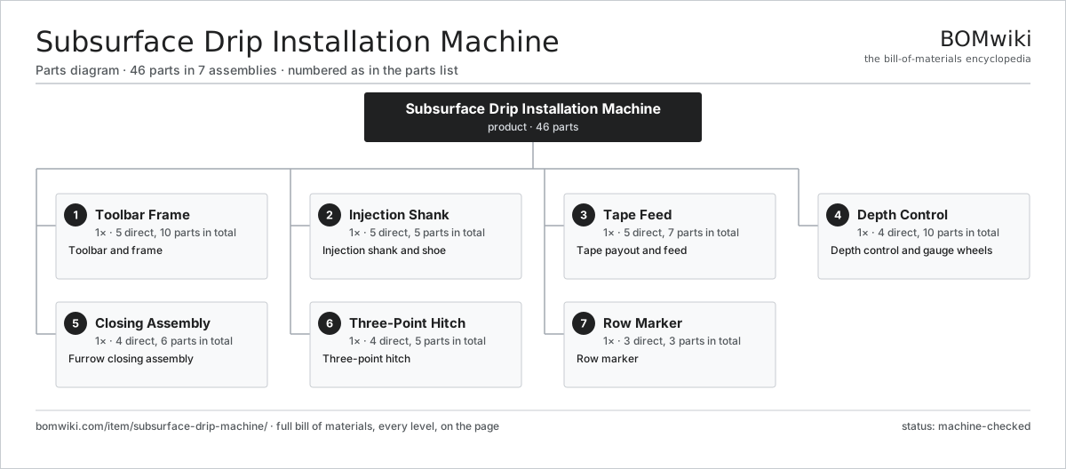
| # | Part | Qty | What it does |
|---|---|---|---|
| 1 | Toolbar Frame 5 parts | 1× | Toolbar and frame |
| 2 | Injection Shank 5 parts | 1× | Injection shank and shoe |
| 3 | Tape Feed 5 parts | 1× | Tape payout and feed |
| 4 | Depth Control 4 parts | 1× | Depth control and gauge wheels |
| 5 | Closing Assembly 4 parts | 1× | Furrow closing assembly |
| 6 | Three-Point Hitch 4 parts | 1× | Three-point hitch |
| 7 | Row Marker 3 parts | 1× | Row marker |
3D model
No 3D model yet. Have a CAD file of this? Add a 3D model — STL renders right on this page; STEP, FreeCAD, and OpenSCAD sources are welcome too (openly licensed, like all 3D models on BOMwiki).
Build & assembly graph
expand / collapse · shared sub-assemblies converge · links to related products · est. labourTap an assembly to expand/collapse · tap a part to open it · use “Open page” for any node · drag to pan, scroll to zoom.
Bill of materials for Subsurface Drip Installation Machine
7 top-level lines · 37 rows shown · 46 parts total · indented to 3 levels| # | Item / sub-assembly | Part no. | Qty/assy | Ext. qty | Parts | Type |
|---|---|---|---|---|---|---|
| 1 | Toolbar Frame 5 parts | subsurface-drip-machine-toolframe | 1× | 1 | 10 | assembly |
| 1.1 | Main Toolbar | subsurface-drip-machine-main-bar | 1× | 1 | · | part |
| 1.2 | Row Clamp | subsurface-drip-machine-row-clamp | 4× | 4 | · | part |
| 1.3 | Gauge Wheel Mount | subsurface-drip-machine-gauge-mount | 2× | 2 | · | part |
| 1.4 | Sheet Metal Panel | sheet-panel | 2× | 2 | · | part |
| 1.5 | Fastener Set | fastener-set | 1× | 1 | · | part |
| 2 | Injection Shank 5 parts | subsurface-drip-machine-shank | 1× | 1 | 5 | assembly |
| 2.1 | Shank Leg | subsurface-drip-machine-shank-leg | 1× | 1 | · | part |
| 2.2 | Knife Point | subsurface-drip-machine-knife-point | 1× | 1 | · | part |
| 2.3 | Tape Shoe | subsurface-drip-machine-tape-shoe | 1× | 1 | · | part |
| 2.4 | Shear Bolt | subsurface-drip-machine-shear-bolt | 1× | 1 | · | part |
| 2.5 | Coil Spring | coil-spring | 1× | 1 | · | part |
| 3 | Tape Feed 5 parts | subsurface-drip-machine-tape-feed | 1× | 1 | 7 | assembly |
| 3.1 | Tape Reel | subsurface-drip-machine-tape-reel | 1× | 1 | · | part |
| 3.2 | Reel Spindle | subsurface-drip-machine-tape-spindle | 1× | 1 | · | part |
| 3.3 | Tension Roller | subsurface-drip-machine-tension-roller | 2× | 2 | · | part |
| 3.4 | Tape Guide | subsurface-drip-machine-tape-guide | 1× | 1 | · | part |
| 3.5 | Ball Bearing | ball-bearing | 2× | 2 | · | part |
| 4 | Depth Control 4 parts | subsurface-drip-machine-depth-control | 1× | 1 | 10 | assembly |
| 4.1 | Gauge Wheel | subsurface-drip-machine-gauge-wheel | 2× | 2 | · | part |
| 4.2 | Depth Screw | subsurface-drip-machine-depth-screw | 2× | 2 | · | part |
| 4.3 | Parallel Arm | subsurface-drip-machine-parallel-arm | 2× | 2 | · | part |
| 4.4 | Ball Bearing | ball-bearing | 4× | 4 | · | part |
| 5 | Closing Assembly 4 parts | subsurface-drip-machine-closing | 1× | 1 | 6 | assembly |
| 5.1 | Closing Disc | subsurface-drip-machine-closing-disc | 2× | 2 | · | part |
| 5.2 | Press Wheel | subsurface-drip-machine-press-wheel | 1× | 1 | · | part |
| 5.3 | Closing Spring | subsurface-drip-machine-closing-spring | 1× | 1 | · | part |
| 5.4 | Ball Bearing | ball-bearing | 2× | 2 | · | part |
| 6 | Three-Point Hitch 4 parts | subsurface-drip-machine-hitch | 1× | 1 | 5 | assembly |
| 6.1 | Hitch Mast | subsurface-drip-machine-hitch-mast | 1× | 1 | · | part |
| 6.2 | Lower Link Pin | subsurface-drip-machine-lower-pin | 2× | 2 | · | part |
| 6.3 | Top Link Pin | subsurface-drip-machine-top-link-pin | 1× | 1 | · | part |
| 6.4 | Fastener Set | fastener-set | 1× | 1 | · | part |
| 7 | Row Marker 3 parts | subsurface-drip-machine-marker | 1× | 1 | 3 | assembly |
| 7.1 | Marker Arm | subsurface-drip-machine-marker-arm | 1× | 1 | · | part |
| 7.2 | Marker Disc | subsurface-drip-machine-marker-disc | 1× | 1 | · | part |
| 7.3 | Coil Spring | coil-spring | 1× | 1 | · | part |
Related products
same domain, ranked by shared parts Feed Grinder Mixer
368 parts · shares 2 with this page
Feed Grinder Mixer
368 parts · shares 2 with this page
 Grain Bagger
206 parts · shares 2 with this page
Grain Bagger
206 parts · shares 2 with this page
 Grape Harvester
69 parts · shares 2 with this page
Grape Harvester
69 parts · shares 2 with this page
 Mobile Grain Dryer
554 parts · shares 2 with this page
Mobile Grain Dryer
554 parts · shares 2 with this page
 Silage Trailer
185 parts · shares 2 with this page
Silage Trailer
185 parts · shares 2 with this page
 Strip-Till Implement
124 parts · shares 2 with this page
Strip-Till Implement
124 parts · shares 2 with this page
Sourcing: possible vendors
Prices, MOQ, and lead times are algorithmic estimates, not quotes, and not claims about these companies. Company mappings are curated by keyword; est. price band $5k–$800k. How estimates work| Vendor | HQ | Specialty | MOQ | Lead time |
|---|---|---|---|---|
| deere.com ↗ | Moline, US | Agriculture & turf | made to order | 14–24 wks |
| cnh.com ↗ | Basildon, GB | Agriculture (Case IH, New Holland) | made to order | 14–24 wks |
|
🇺🇸AGCO
agcocorp.com ↗
|
Duluth, US | Agriculture (Fendt, Massey Ferguson) | made to order | 14–24 wks |
|
🇩🇪Claas
claas.com ↗
|
Harsewinkel, DE | Harvesters & tractors | made to order | 14–24 wks |
|
🇯🇵Kubota
kubota.com ↗
|
Osaka, JP | Compact tractors & equipment | made to order | 14–24 wks |
1,008-word article