Bale Shredder Feeder
ProductOverview
A bale shredder feeder takes a baled crop, a round bale of straw or a square bale of silage, and tears it back into loose material so it can be spread as bedding or laid out as feed. The machine is trailed behind a farm tractor and driven from the tractor power take-off. A bale sits in a tub above a fast-spinning rotor; the Shredding Rotor flails material off the bottom of the bale, the loose straw or forage is thrown through a Discharge System chute, and a rotating deflector aims the stream into a stall, along a feed fence, or into a trough. One pass that would take a worker many minutes by hand is done in seconds, and the operator never leaves the cab.
The machine combines a holding Bale Chamber, the shredding Shredding Rotor, the Discharge System system, a PTO Driveline from the tractor, the Hydraulic System that load the bale and open the chamber, a Chassis for transport, and a Control Box box in the cab.
The bale chamber
The Bale Chamber holds the bale and feeds it steadily into the rotor. Its Tub Shell is a welded steel tub that cradles the bale above the rotor mouth. A Floor Chain carrying bolt-on Floor Slat cross bars walks the bale forward, while a set of Rotation Roller rollers spin a round bale so the rotor peels it in even layers rather than digging a hole in one spot. Sprung Bale Retainer bars press the bale down so it cannot climb out or feed in lumps. Even feed matters: a bale that drops in all at once will bog the rotor and stall the tractor, so the chamber meters the bale at a rate the rotor can clear. The rollers and floor chain ride on Ball Bearing units and are held together with a Fastener Set.
The shredding rotor
The Shredding Rotor does the work. A balanced Rotor Drum carries two dozen or more swinging Flail hammers, each hung on a Flail Pin so it folds back if it meets a stone or a frozen lump instead of snapping the drum. As the drum spins, the flails beat material off the bale face and shear it against a row of fixed Counter-Knife blades and the Shear Bar at the rotor mouth, which sets cut length and clearance. The drum runs on a Rotor Shaft in heavy Ball Bearing mounts. The rotor is the part most exposed to wear and shock, so the flails and shear bar are made to be replaced as they wear; sand baled with the crop is the main enemy and grinds hammers down over a season.
Driving the rotor
Power comes from the tractor through the PTO Driveline. A telescoping PTO Shaft with universal joints carries torque from the tractor power take-off into an angle Gearbox Housing whose Helical Gear Pair bevel set turns the drive across to the rotor. A Slip Clutch sits in the line so that if a flail jams on a wire or a frozen core the clutch slips rather than letting the gearbox or shaft break. A Flywheel stores energy between flail bites so each bite does not lug the tractor down, and a pair of Drive Belt belts couple the gearbox output to the rotor. The gearbox runs in oil sealed by two Oil Seal seals and rides on four Ball Bearing units.
Loading and hydraulics
The Hydraulic System make the machine a one-person job. A side Loading Arm reaches down, grabs a bale off the ground, and lifts it into the tub, so the operator never gets off the tractor. Two Hydraulic Cylinder rams drive the loading arm and the chamber door. Oil from the tractor remotes runs through a Valve Block manifold and a Hose Set of hoses and couplers, with an O-Ring Set sealing the joints. The same hydraulic circuit spins the Deflector Motor that aims the discharge, so the operator controls loading, shredding direction, and door from the seat.
Discharge and placement
The Discharge System system decides where the material lands. Shredded straw or forage is thrown up the Discharge Chute and out through a rotating Deflector hood that the operator swings side to side and tilts up or down to lay an even bed across a pen or to drop feed precisely along a trough. Bolt-in Wear Liner wear plates protect the chute from the constant blast of grit. For bedding work the deflector throws straw far and wide to cover stalls; for feeding it lays a tidy windrow so cattle waste less.
Chassis, controls, and use
The Chassis carries the machine on the road: a welded Main Frame ties the tub, rotor, and running gear together, a Drawbar hitches to the tractor, and a Axle on two Road Wheel tyres rolls it between yards, with a Parking Jack to support the drawbar when parked. The Control Box box runs everything from the cab through a small Bare PCB board and Microcontroller, with a Control Panel of switches and a joystick. Many machines add Load Cell weigh cells so a known weight of feed can be laid out for ration control. Bale shredders are standard kit on beef, dairy, and sheep farms with straw-bedded yards: one tractor and one operator can bed a whole shed or feed a row of pens in minutes, work that once took several hands with forks.
Bale Shredder Feeder parts and their functions
7 top-level parts · 142 parts in total · full bill of materials below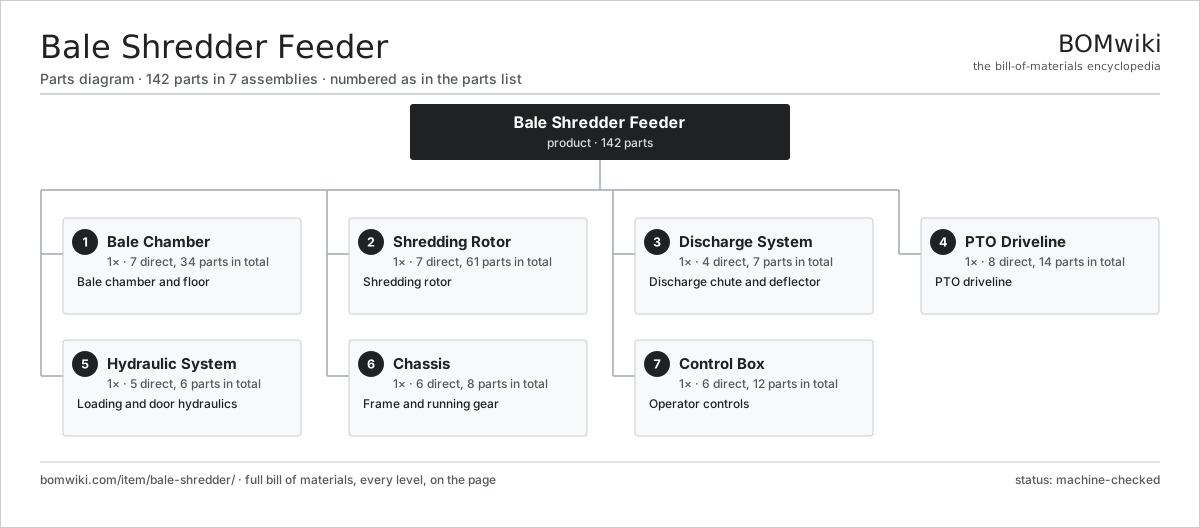
| # | Part | Qty | What it does |
|---|---|---|---|
| 1 | Bale Chamber 7 parts | 1× | Bale chamber and floor |
| 2 | Shredding Rotor 7 parts | 1× | Shredding rotor |
| 3 | Discharge System 4 parts | 1× | Discharge chute and deflector |
| 4 | PTO Driveline 8 parts | 1× | PTO driveline |
| 5 | Hydraulic System 5 parts | 1× | Loading and door hydraulics |
| 6 | Chassis 6 parts | 1× | Frame and running gear |
| 7 | Control Box 6 parts | 1× | Operator controls |
3D model
No 3D model yet. Have a CAD file of this? Add a 3D model — STL renders right on this page; STEP, FreeCAD, and OpenSCAD sources are welcome too (openly licensed, like all 3D models on BOMwiki).
Build & assembly graph
expand / collapse · shared sub-assemblies converge · links to related products · est. labourTap an assembly to expand/collapse · tap a part to open it · use “Open page” for any node · drag to pan, scroll to zoom.
Bill of materials for Bale Shredder Feeder
7 top-level lines · 50 rows shown · 142 parts total · indented to 3 levels| # | Item / sub-assembly | Part no. | Qty/assy | Ext. qty | Parts | Type |
|---|---|---|---|---|---|---|
| 1 | Bale Chamber 7 parts | bale-shredder-chamber | 1× | 1 | 34 | assembly |
| 1.1 | Tub Shell | bale-shredder-tub-shell | 1× | 1 | · | part |
| 1.2 | Floor Chain | bale-shredder-floor-chain | 1× | 1 | · | part |
| 1.3 | Floor Slat | bale-shredder-floor-slat | 18× | 18 | · | part |
| 1.4 | Rotation Roller | bale-shredder-rotation-roller | 3× | 3 | · | part |
| 1.5 | Bale Retainer | bale-shredder-retainer | 2× | 2 | · | part |
| 1.6 | Ball Bearing | ball-bearing | 8× | 8 | · | part |
| 1.7 | Fastener Set | fastener-set | 1× | 1 | · | part |
| 2 | Shredding Rotor 7 parts | bale-shredder-rotor | 1× | 1 | 61 | assembly |
| 2.1 | Rotor Drum | bale-shredder-rotor-drum | 1× | 1 | · | part |
| 2.2 | Flail | bale-shredder-flail | 24× | 24 | · | part |
| 2.3 | Flail Pin | bale-shredder-flail-pin | 24× | 24 | · | part |
| 2.4 | Counter-Knife | bale-shredder-counter-knife | 8× | 8 | · | part |
| 2.5 | Rotor Shaft | bale-shredder-rotor-shaft | 1× | 1 | · | part |
| 2.6 | Ball Bearing | ball-bearing | 2× | 2 | · | part |
| 2.7 | Shear Bar | bale-shredder-shear-bar | 1× | 1 | · | part |
| 3 | Discharge System 4 parts | bale-shredder-discharge | 1× | 1 | 7 | assembly |
| 3.1 | Discharge Chute | bale-shredder-chute | 1× | 1 | · | part |
| 3.2 | Deflector | bale-shredder-deflector | 1× | 1 | · | part |
| 3.3 | Deflector Motor | bale-shredder-deflector-motor | 1× | 1 | · | part |
| 3.4 | Wear Liner | bale-shredder-liner | 4× | 4 | · | part |
| 4 | PTO Driveline 8 parts | bale-shredder-driveline | 1× | 1 | 14 | assembly |
| 4.1 | PTO Shaft | bale-shredder-pto-shaft | 1× | 1 | · | part |
| 4.2 | Gearbox Housing | gearbox-housing | 1× | 1 | · | part |
| 4.3 | Helical Gear Pair | gear-pair | 2× | 2 | · | part |
| 4.4 | Slip Clutch | bale-shredder-slip-clutch | 1× | 1 | · | part |
| 4.5 | Flywheel | bale-shredder-flywheel | 1× | 1 | · | part |
| 4.6 | Drive Belt | drive-belt | 2× | 2 | · | part |
| 4.7 | Oil Seal | oil-seal | 2× | 2 | · | part |
| 4.8 | Ball Bearing | ball-bearing | 4× | 4 | · | part |
| 5 | Hydraulic System 5 parts | bale-shredder-hydraulics | 1× | 1 | 6 | assembly |
| 5.1 | Loading Arm | bale-shredder-loading-arm | 1× | 1 | · | part |
| 5.2 | Hydraulic Cylinder | bale-shredder-cylinder | 2× | 2 | · | part |
| 5.3 | Valve Block | bale-shredder-valve-block | 1× | 1 | · | part |
| 5.4 | Hose Set | bale-shredder-hose-set | 1× | 1 | · | part |
| 5.5 | O-Ring Set | oring-set | 1× | 1 | · | part |
| 6 | Chassis 6 parts | bale-shredder-chassis | 1× | 1 | 8 | assembly |
| 6.1 | Main Frame | bale-shredder-frame | 1× | 1 | · | part |
| 6.2 | Drawbar | bale-shredder-drawbar | 1× | 1 | · | part |
| 6.3 | Axle | bale-shredder-axle | 1× | 1 | · | part |
| 6.4 | Road Wheel | bale-shredder-wheel | 2× | 2 | · | part |
| 6.5 | Parking Jack | bale-shredder-jack | 1× | 1 | · | part |
| 6.6 | Ball Bearing | ball-bearing | 2× | 2 | · | part |
| 7 | Control Box 6 parts | bale-shredder-controls | 1× | 1 | 12 | assembly |
| 7.1 | Bare PCB | pcb-bare | 1× | 1 | · | part |
| 7.2 | Microcontroller | mcu | 1× | 1 | · | part |
| 7.3 | Control Panel | bale-shredder-control-panel | 1× | 1 | · | part |
| 7.4 | Load Cell | bale-shredder-load-cell | 2× | 2 | · | part |
| 7.5 | Connector | connector | 6× | 6 | · | part |
| 7.6 | Wire Bundle | wire-bundle | 1× | 1 | · | part |
Related products
same domain, ranked by shared parts Cotton Stripper
208 parts · shares 8 with this page
Cotton Stripper
208 parts · shares 8 with this page
 Feed Grinder Mixer
368 parts · shares 8 with this page
Feed Grinder Mixer
368 parts · shares 8 with this page
 Feed Mixer Wagon
133 parts · shares 8 with this page
Feed Mixer Wagon
133 parts · shares 8 with this page
 Grain Combine
211 parts · shares 8 with this page
Grain Combine
211 parts · shares 8 with this page
 Large Round Baler
783 parts · shares 8 with this page
Large Round Baler
783 parts · shares 8 with this page
 Mobile Grain Dryer
554 parts · shares 8 with this page
Mobile Grain Dryer
554 parts · shares 8 with this page
Sourcing: possible vendors
Prices, MOQ, and lead times are algorithmic estimates, not quotes, and not claims about these companies. Company mappings are curated by keyword; est. price band $5k–$800k. How estimates work| Vendor | HQ | Specialty | MOQ | Lead time |
|---|---|---|---|---|
| deere.com ↗ | Moline, US | Agriculture & turf | made to order | 14–24 wks |
| cnh.com ↗ | Basildon, GB | Agriculture (Case IH, New Holland) | made to order | 14–24 wks |
|
🇺🇸AGCO
agcocorp.com ↗
|
Duluth, US | Agriculture (Fendt, Massey Ferguson) | made to order | 14–24 wks |
|
🇩🇪Claas
claas.com ↗
|
Harsewinkel, DE | Harvesters & tractors | made to order | 14–24 wks |
|
🇯🇵Kubota
kubota.com ↗
|
Osaka, JP | Compact tractors & equipment | made to order | 14–24 wks |
976-word article