Lateral Move Irrigation Machine
ProductOverview
A lateral move irrigation machine, also called a linear move, is a long water boom carried on a row of wheeled towers that rolls across a field in a straight line. It waters the crop in parallel passes, covering a rectangular field from one end to the other and then returning. The machine in this article is built from Pipe Truss Span pipe truss sections joined at each Drive Tower, fed from a central Power Cart that carries the engine, generator, and water inlet.
The key difference from a center pivot is geometry. A center pivot rotates around a fixed anchor, so the outer end travels far faster than the inner end and water must be graded along the pipe to keep application even. A lateral move has no anchor: every tower travels at the same speed in the same direction, so the application rate is uniform along the whole length by design. That makes a lateral move the better fit for rectangular fields, where a pivot would leave the corners dry. The cost is that a lateral move must carry its own water with it as it moves, either by trailing a hose or by drawing from a channel that runs the length of the field.
How it works
Water enters at the Power Cart, where a Booster Pump raises it to operating pressure, usually 1 to 4 bar. The pressurized water flows out along the Span Pipe of each span, which doubles as the top chord of a truss. Truss rods and angle braces under the pipe carry the bending load so the pipe can bridge 38 to 60 m between towers without sagging into the crop.
Along each span, the Sprinkler Line taps the pipe at regular intervals. Each outlet has a Gooseneck Riser riser, a Pressure Regulator that holds the emitter at a fixed pressure regardless of where it sits on the line, and a Sprinkler Head or low-pressure bubbler on a drop hose near the canopy. Because every regulator delivers the same pressure and every tower moves at the same speed, the depth of water applied is constant across the field width.
The whole structure crawls forward on the Tower Wheel pairs at each tower. Each wheel is turned by a Wheel Gearmotor, an electric motor reduced through a worm gearset, and a final hub gearbox. The generator on the cart feeds three-phase power down the Span Cable runs to every tower motor.
Subsystems
The machine breaks into nine top-level groups: the power cart, the pipe truss spans, the drive towers, the sprinkler lines, the guidance system, the end gun, the water supply connection, the electrical distribution, and the safety circuit. The power cart is the only self-contained unit; the spans and towers repeat along the length, so a longer machine simply adds more of each. Quantities in the bill of materials assume a six-span machine, which is a common mid-size configuration of roughly 250 to 350 m.
Drive and alignment
Keeping a long line straight is the central control problem. If one tower runs ahead of its neighbors the pipe between them bends, and over a full machine those small errors would accumulate into a curve. The fix is simple and mechanical: an Alignment Switch sits at every span joint and senses whether the next tower is leading or lagging. When a tower falls behind, its switch starts the motor; when it catches up, the switch stops it. The towers therefore move in short bursts, each chasing the one beside it, and the line stays straight to within a few centimetres.
Travel speed, and with it application depth, is set by a Percent Timer in the Control Panel. The timer cycles the lead unit on and off over a fixed period; a higher on-percentage means faster travel and a shallower application. The whole sequence runs on a Programmable Controller.
A lateral move also needs an outside reference to hold its overall heading, since alignment switches only keep towers square to each other, not the machine square to the field. That reference comes from the Guidance Sensor, which may be a furrow follower wheel riding in a guide trench, an antenna tracking a buried cable, or a GPS receiver. A steering actuator on the lead unit corrects the heading.
Water application
A lateral move can apply water more uniformly than almost any other field machine because every emitter sees the same regulated pressure and moves at the same ground speed. Distribution uniformity above 90 percent is normal on a well-set machine. Emitter choice tunes the trade-off: impact and rotator heads throw a wide pattern from above the canopy, while LEPA Bubbler outlets on drop hoses place water at the soil surface to cut evaporation and wind drift, which matters in dry, windy regions. Coverage past the final tower is extended by the End Gun and Boom-Back boom and big gun.
Variants
Machines are configured by water feed and power. Hose-fed units trail a Drag Hose from a line of hydrants, with a reel paying it out and recovering it; these suit fields where a buried mainline already exists. Canal-fed units draw from a Canal Feed Trough running the length of the field through a screened Floating Intake, which removes the hose entirely at the cost of digging and lining the channel. Some machines are convertible, adding a pivot point at one end so the same hardware can run as a lateral move along the field and then pivot to reach an irregular corner.
Common failures
The most frequent faults are alignment-related: a sticking Alignment Switch leaves a tower running long or never starting, which bows the line and can trip the Tower Tilt Switch on a leaning tower. Wheel gearmotors fail from water ingress past a worn output seal, which lets the worm gearset rust and seize. Pressure regulators clog or wear open, ruining uniformity, and goosenecks and drop hoses crack from sun and flexing. On the supply side, a torn drag hose or a fouled floating intake screen starves the booster pump, which the Supply Pressure Sensor should catch before the pump runs dry. The Safety Circuit backstops all of this, cutting drive power on low water pressure or an over-run at the end tower.
Lateral Move Irrigation Machine parts and their functions
9 top-level parts · 1,054 parts in total · full bill of materials below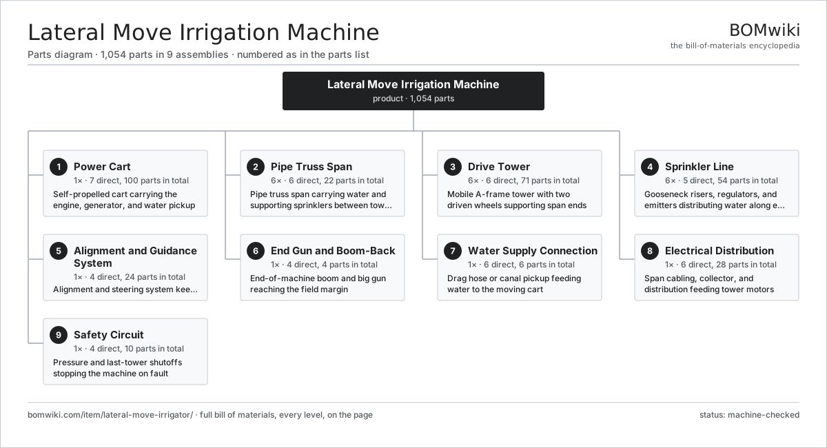
| # | Part | Qty | What it does |
|---|---|---|---|
| 1 | Power Cart 7 parts | 1× | Self-propelled cart carrying the engine, generator, and water pickup |
| 2 | Pipe Truss Span 6 parts | 6× | Pipe truss span carrying water and supporting sprinklers between towers |
| 3 | Drive Tower 6 parts | 6× | Mobile A-frame tower with two driven wheels supporting span ends |
| 4 | Sprinkler Line 5 parts | 6× | Gooseneck risers, regulators, and emitters distributing water along each span |
| 5 | Alignment and Guidance System 4 parts | 1× | Alignment and steering system keeping the machine straight and square |
| 6 | End Gun and Boom-Back 4 parts | 1× | End-of-machine boom and big gun reaching the field margin |
| 7 | Water Supply Connection 6 parts | 1× | Drag hose or canal pickup feeding water to the moving cart |
| 8 | Electrical Distribution 6 parts | 1× | Span cabling, collector, and distribution feeding tower motors |
| 9 | Safety Circuit 4 parts | 1× | Pressure and last-tower shutoffs stopping the machine on fault |
3D model
No 3D model yet. Have a CAD file of this? Add a 3D model — STL renders right on this page; STEP, FreeCAD, and OpenSCAD sources are welcome too (openly licensed, like all 3D models on BOMwiki).
Build & assembly graph
expand / collapse · shared sub-assemblies converge · links to related products · est. labourTap an assembly to expand/collapse · tap a part to open it · use “Open page” for any node · drag to pan, scroll to zoom.
Bill of materials for Lateral Move Irrigation Machine
9 top-level lines · 99 rows shown · 1,054 parts total · indented to 3 levels| # | Item / sub-assembly | Part no. | Qty/assy | Ext. qty | Parts | Type |
|---|---|---|---|---|---|---|
| 1 | Power Cart 7 parts | lateral-move-irrigator-power-cart | 1× | 1 | 100 | assembly |
| 1.1 | Cart Chassis | lateral-move-irrigator-cart-chassis | 1× | 1 | · | part |
| 1.2 | Diesel Engine 8 parts | lateral-move-irrigator-diesel-engine | 1× | 1 | 10 | assembly |
| 1.2.1 | Engine Block | lateral-move-irrigator-engine-block | 1× | 1 | · | part |
| 1.2.2 | Engine Radiator | lateral-move-irrigator-engine-radiator | 1× | 1 | · | part |
| 1.2.3 | Starter Motor | lateral-move-irrigator-engine-starter | 1× | 1 | · | part |
| 1.2.4 | Charging Alternator | lateral-move-irrigator-engine-alternator | 1× | 1 | · | part |
| 1.2.5 | Fuel Filter | lateral-move-irrigator-fuel-filter | 2× | 2 | · | part |
| 1.2.6 | Air Cleaner | lateral-move-irrigator-air-cleaner | 1× | 1 | · | part |
| 1.2.7 | Oil Seal | oil-seal | 2× | 2 | · | part |
| 1.2.8 | Fastener Set | fastener-set | 1× | 1 | · | part |
| 1.3 | Generator 5 parts | lateral-move-irrigator-generator | 1× | 1 | 26 | assembly |
| 1.3.1 | Stator Assembly 3 parts + deeper › | stator-assembly | 1× | 1 | 3 | assembly |
| 1.3.2 | Rotor Assembly 4 parts + deeper › | rotor-assembly | 1× | 1 | 19 | assembly |
| 1.3.3 | Ball Bearing | ball-bearing | 2× | 2 | · | part |
| 1.3.4 | Voltage Regulator | lateral-move-irrigator-generator-avr | 1× | 1 | · | part |
| 1.3.5 | Generator Terminal Box | lateral-move-irrigator-generator-terminal-box | 1× | 1 | · | part |
| 1.4 | Fuel Tank | lateral-move-irrigator-fuel-tank | 1× | 1 | · | part |
| 1.5 | Booster Pump 5 parts | lateral-move-irrigator-booster-pump | 1× | 1 | 6 | assembly |
| 1.5.1 | Pump Impeller | lateral-move-irrigator-pump-impeller | 1× | 1 | · | part |
| 1.5.2 | Pump Casing | lateral-move-irrigator-pump-casing | 1× | 1 | · | part |
| 1.5.3 | Ball Bearing | ball-bearing | 2× | 2 | · | part |
| 1.5.4 | Oil Seal | oil-seal | 1× | 1 | · | part |
| 1.5.5 | O-Ring Set | oring-set | 1× | 1 | · | part |
| 1.6 | Cart Wheel | lateral-move-irrigator-cart-wheels | 2× | 2 | · | part |
| 1.7 | Cart Gearmotor 6 parts | lateral-move-irrigator-cart-gearmotor | 2× | 2 | 27 | assembly |
| 1.7.1 | Stator Assembly 3 parts + deeper › | stator-assembly | 1× | 2 | 3 | assembly |
| 1.7.2 | Rotor Assembly 4 parts + deeper › | rotor-assembly | 1× | 2 | 19 | assembly |
| 1.7.3 | Helical Gear Pair | gear-pair | 1× | 2 | · | part |
| 1.7.4 | Gearbox Housing | gearbox-housing | 1× | 2 | · | part |
| 1.7.5 | Ball Bearing | ball-bearing | 2× | 4 | · | part |
| 1.7.6 | Oil Seal | oil-seal | 1× | 2 | · | part |
| 2 | Pipe Truss Span 6 parts | lateral-move-irrigator-span | 6× | 6 | 22 | assembly |
| 2.1 | Span Pipe | lateral-move-irrigator-span-pipe | 1× | 6 | · | part |
| 2.2 | Truss Rod | lateral-move-irrigator-truss-rod | 4× | 24 | · | part |
| 2.3 | Truss Strut | lateral-move-irrigator-truss-strut | 6× | 36 | · | part |
| 2.4 | Angle Brace | lateral-move-irrigator-angle-brace | 8× | 48 | · | part |
| 2.5 | Span Coupler | lateral-move-irrigator-span-coupler | 2× | 12 | · | part |
| 2.6 | Fastener Set | fastener-set | 1× | 6 | · | part |
| 3 | Drive Tower 6 parts | lateral-move-irrigator-drive-tower | 6× | 6 | 71 | assembly |
| 3.1 | Tower A-Frame | lateral-move-irrigator-tower-aframe | 1× | 6 | · | part |
| 3.2 | Tower Wheel | lateral-move-irrigator-tower-wheel | 2× | 12 | · | part |
| 3.3 | Wheel Gearmotor 6 parts | lateral-move-irrigator-tower-gearmotor | 2× | 12 | 28 | assembly |
| 3.3.1 | Stator Assembly 3 parts + deeper › | stator-assembly | 1× | 12 | 3 | assembly |
| 3.3.2 | Rotor Assembly 4 parts + deeper › | rotor-assembly | 1× | 12 | 19 | assembly |
| 3.3.3 | Helical Gear Pair | gear-pair | 1× | 12 | · | part |
| 3.3.4 | Gearbox Housing | gearbox-housing | 1× | 12 | · | part |
| 3.3.5 | Ball Bearing | ball-bearing | 2× | 24 | · | part |
| 3.3.6 | Oil Seal | oil-seal | 2× | 24 | · | part |
| 3.4 | Drive Shaft | lateral-move-irrigator-drive-shaft | 1× | 6 | · | part |
| 3.5 | Wheel Final Gearbox 4 parts | lateral-move-irrigator-tower-gearbox | 2× | 12 | 5 | assembly |
| 3.5.1 | Helical Gear Pair | gear-pair | 1× | 12 | · | part |
| 3.5.2 | Gearbox Housing | gearbox-housing | 1× | 12 | · | part |
| 3.5.3 | Ball Bearing | ball-bearing | 2× | 24 | · | part |
| 3.5.4 | Oil Seal | oil-seal | 1× | 12 | · | part |
| 3.6 | Fastener Set | fastener-set | 1× | 6 | · | part |
| 4 | Sprinkler Line 5 parts | lateral-move-irrigator-sprinkler-line | 6× | 6 | 54 | assembly |
| 4.1 | Gooseneck Riser | lateral-move-irrigator-gooseneck | 12× | 72 | · | part |
| 4.2 | Pressure Regulator | lateral-move-irrigator-pressure-regulator | 12× | 72 | · | part |
| 4.3 | Sprinkler Head | lateral-move-irrigator-sprinkler-head | 12× | 72 | · | part |
| 4.4 | Drop Hose | lateral-move-irrigator-drop-hose | 12× | 72 | · | part |
| 4.5 | LEPA Bubbler | lateral-move-irrigator-lepa-bubbler | 6× | 36 | · | part |
| 5 | Alignment and Guidance System 4 parts | lateral-move-irrigator-guidance | 1× | 1 | 24 | assembly |
| 5.1 | Alignment Switch | lateral-move-irrigator-alignment-switch | 5× | 5 | · | part |
| 5.2 | Control Panel 5 parts | lateral-move-irrigator-control-panel | 1× | 1 | 17 | assembly |
| 5.2.1 | Programmable Controller 3 parts + deeper › | lateral-move-irrigator-plc | 1× | 1 | 3 | assembly |
| 5.2.2 | LCD Panel | lcd-panel | 1× | 1 | · | part |
| 5.2.3 | Relay | relay | 6× | 6 | · | part |
| 5.2.4 | Motor Contactor | lateral-move-irrigator-contactor | 6× | 6 | · | part |
| 5.2.5 | Percent Timer | lateral-move-irrigator-percent-timer | 1× | 1 | · | part |
| 5.3 | Guidance Sensor | lateral-move-irrigator-guidance-sensor | 1× | 1 | · | part |
| 5.4 | Steering Actuator | lateral-move-irrigator-steer-actuator | 1× | 1 | · | part |
| 6 | End Gun and Boom-Back 4 parts | lateral-move-irrigator-end-gun | 1× | 1 | 4 | assembly |
| 6.1 | Boom-Back | lateral-move-irrigator-boom-back | 1× | 1 | · | part |
| 6.2 | Big Gun | lateral-move-irrigator-big-gun | 1× | 1 | · | part |
| 6.3 | End-Gun Booster Valve | lateral-move-irrigator-booster-valve | 1× | 1 | · | part |
| 6.4 | End-Gun Pressure Switch | lateral-move-irrigator-end-pressure-switch | 1× | 1 | · | part |
| 7 | Water Supply Connection 6 parts | lateral-move-irrigator-water-supply | 1× | 1 | 6 | assembly |
| 7.1 | Drag Hose | lateral-move-irrigator-drag-hose | 1× | 1 | · | part |
| 7.2 | Hose Reel | lateral-move-irrigator-hose-reel | 1× | 1 | · | part |
| 7.3 | Inlet Swivel | lateral-move-irrigator-inlet-swivel | 1× | 1 | · | part |
| 7.4 | Canal Feed Trough | lateral-move-irrigator-canal-trough | 1× | 1 | · | part |
| 7.5 | Floating Intake | lateral-move-irrigator-floating-intake | 1× | 1 | · | part |
| 7.6 | Supply Pressure Sensor | lateral-move-irrigator-supply-pressure-sensor | 1× | 1 | · | part |
| 8 | Electrical Distribution 6 parts | lateral-move-irrigator-electrical | 1× | 1 | 28 | assembly |
| 8.1 | Span Cable | lateral-move-irrigator-span-cable | 6× | 6 | · | part |
| 8.2 | Inter-Span Collector | lateral-move-irrigator-collector | 5× | 5 | · | part |
| 8.3 | Wire Bundle | wire-bundle | 1× | 1 | · | part |
| 8.4 | Connector | connector | 12× | 12 | · | part |
| 8.5 | Main Disconnect | lateral-move-irrigator-disconnect | 1× | 1 | · | part |
| 8.6 | Control Power Supply 3 parts | lateral-move-irrigator-power-supply | 1× | 1 | 3 | assembly |
| 8.6.1 | Power Supply | power-supply | 1× | 1 | · | part |
| 8.6.2 | Bare PCB | pcb-bare | 1× | 1 | · | part |
| 8.6.3 | SMD Passive (R/C/L) | smd-passives | 1× | 1 | · | part |
| 9 | Safety Circuit 4 parts | lateral-move-irrigator-safety-circuit | 1× | 1 | 10 | assembly |
| 9.1 | Last-Tower Shutoff | lateral-move-irrigator-last-tower-shutoff | 1× | 1 | · | part |
| 9.2 | Pressure Sensor | pressure-sensor | 1× | 1 | · | part |
| 9.3 | Tower Tilt Switch | lateral-move-irrigator-tilt-switch | 6× | 6 | · | part |
| 9.4 | Emergency Stop | lateral-move-irrigator-estop | 2× | 2 | · | part |
Related products
same domain, ranked by shared parts Center-Pivot Irrigator
945 parts · shares 20 with this page
Center-Pivot Irrigator
945 parts · shares 20 with this page
 Mobile Grain Dryer
554 parts · shares 20 with this page
Mobile Grain Dryer
554 parts · shares 20 with this page
 Robotic Milking System
153 parts · shares 18 with this page
Robotic Milking System
153 parts · shares 18 with this page
 Articulated Tractor
1,229 parts · shares 19 with this page
Articulated Tractor
1,229 parts · shares 19 with this page
 Large Round Baler
783 parts · shares 19 with this page
Large Round Baler
783 parts · shares 19 with this page
 Orchard Tractor
562 parts · shares 19 with this page
Orchard Tractor
562 parts · shares 19 with this page
Sourcing: possible vendors
Prices, MOQ, and lead times are algorithmic estimates, not quotes, and not claims about these companies. Company mappings are curated by keyword; est. price band $5k–$800k. How estimates work| Vendor | HQ | Specialty | MOQ | Lead time |
|---|---|---|---|---|
| deere.com ↗ | Moline, US | Agriculture & turf | made to order | 14–24 wks |
| cnh.com ↗ | Basildon, GB | Agriculture (Case IH, New Holland) | made to order | 14–24 wks |
|
🇺🇸AGCO
agcocorp.com ↗
|
Duluth, US | Agriculture (Fendt, Massey Ferguson) | made to order | 14–24 wks |
|
🇩🇪Claas
claas.com ↗
|
Harsewinkel, DE | Harvesters & tractors | made to order | 14–24 wks |
|
🇯🇵Kubota
kubota.com ↗
|
Osaka, JP | Compact tractors & equipment | made to order | 14–24 wks |
1,128-word article