Slurry Tanker
ProductOverview
A slurry tanker is a trailed agricultural implement that collects, transports, and field-applies liquid manure (slurry) from livestock housing and storage stores. The Tank Vessel is a cylindrical galvanized-steel barrel mounted on a Running Gear and towed behind a tractor through the Drawbar. Capacities run from around 7,000 L on small single-axle machines to 30,000 L on tridem units, with 10,000–18,000 L the common range on mixed farms. The same tank handles cattle, pig, and digestate slurry, returning nitrogen, phosphorus, and potassium to grassland and arable ground. A loaded 18,000 L tanker weighs 30 t or more on the road, so the machine is also a heavy haulage trailer: it has to brake, corner, and ride safely while carrying a sloshing liquid load that can shift its centre of gravity in a fraction of a second.
Tank vessel
The Barrel Shell is a rolled steel cylinder closed by two pressed Dished End heads, hot-dip galvanized inside and out to resist the corrosive, abrasive load. Internal Anti-Surge Baffle panels damp the surge of several tonnes of liquid during braking and on slopes, which keeps the trailer stable. A Manhole Cover gives access for cleaning and inspection, and a Sight Gauge shows the fill level. The barrel sits on a welded Chassis Cradle that carries the load into the suspension. Because the tank operates under both vacuum and pressure, the shell is built and tested as a low-pressure vessel.
How vacuum filling and discharge work
The machine fills and empties using air. The Rotary Vane Vacuum Pump, a lubricated Pump Rotor running on six sliding Pump Vane blades, is driven from the tractor through the PTO Shaft and the belt Pump Driveline. Moving 8,000–14,000 L/min of air, it draws the tank down to roughly 0.85 bar vacuum so atmospheric pressure pushes slurry up the Suction Hose and into the barrel. A 10,000 L tank fills in 3–8 minutes through the self-fill Filling Arm, which positions the Dock Valve at the store. To empty, the Changeover Valve reverses the pump so the tank is pressurized to about 0.5 bar, forcing slurry out of the Rear Gate Valve. A Pressure/Vacuum Relief Valve caps both pressure and vacuum, and a primary float plus secondary trap in the Anti-Overfill Shutoff stop liquid carrying over into the pump and ruining it. Vane lubrication comes from the Oil Reservoir, which drip-feeds oil into the air stream to keep the vanes sealing against the bore. The pump runs at PTO speed of 540 or 1000 rpm and pulls 30–60 HP while filling, so a tractor of 80 HP suits a 10,000 L machine and 150–200 HP suits the largest tanks. Air piping between pump and tank runs through the Air Line.
Application methods
Three applicators trade speed against precision. The Splash Plate deflects slurry into a wide broadcast fan, which is fast and cheap but spreads odour and loses ammonia to the air. The Dribble Bar feeds a Macerator/Distributor that chops and divides the flow through a Distributor Head into many Outlet Hose drops, laying parallel bands at ground level across a 6–24 m Application Boom. A trailing-shoe version adds a sprung Trailing Shoe that parts the crop and places slurry on the soil under the canopy, cutting losses further. Shallow injectors, a fourth option, cut slots and bury the slurry for the lowest emissions and least odour, at the cost of draft and forward speed. As a rule, broadcast spreading covers the most ground per hour but a dribble bar or trailing shoe at 12–18 m working width places slurry where the crop uses it, lifts the share of nitrogen retained, and lets the operator spread closer to growing crops without scorch.
Materials
Steel dominates the build. The shell, ends, Chassis Cradle, drawbar, and boom frames are S355 structural steel, galvanized where they meet slurry. Cast iron is used for the Pump Housing. Sliding vanes are fibre or composite, gaskets and the Manhole Gasket are nitrile or EPDM, and hoses are reinforced rubber sized 6 in or 8 in bore.
Variants and operation
Tankers scale by capacity and axle count: single axle up to about 12,000 L, tandem to 20,000 L, and tridem bogies beyond. Larger machines need 150–200 HP and 1000 rpm PTO, with laden gross weight reaching 30–40 t, so the Flotation Tire set and the sprung Bogie Suspension matter for road manners and soil protection. Air or hydraulic drum brakes through the Brake System are mandatory at these weights. Many regions now restrict splash-plate spreading and require low-emission applicators and a Magnetic Flow Meter with a Rate Controller for accurate, recorded application rates and closed spreading periods.
Maintenance
Daily checks cover the Oil Reservoir drip rate, the Pressure/Vacuum Relief Valve, and the Anti-Overfill Shutoff float. After each season the Pump Vane blades are inspected for wear and the pump is flushed. The Hub Assembly bearings and PTO Shaft joints are greased on schedule, the Shear/Slip Clutch is checked for slip, and the macerator Cutter Blade edges are renewed when discharge slows. Hydraulic oil and the Hydraulic Filter are changed at the recommended interval.
Slurry Tanker parts and their functions
8 top-level parts · 467 parts in total · full bill of materials below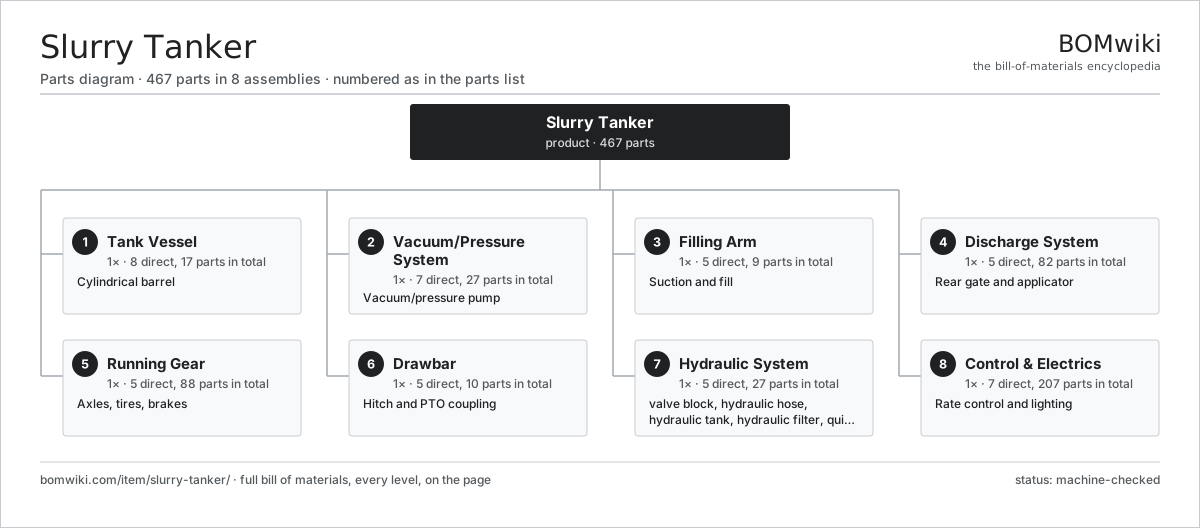
| # | Part | Qty | What it does |
|---|---|---|---|
| 1 | Tank Vessel 8 parts | 1× | Cylindrical barrel |
| 2 | Vacuum/Pressure System 7 parts | 1× | Vacuum/pressure pump |
| 3 | Filling Arm 5 parts | 1× | Suction and fill |
| 4 | Discharge System 5 parts | 1× | Rear gate and applicator |
| 5 | Running Gear 5 parts | 1× | Axles, tires, brakes |
| 6 | Drawbar 5 parts | 1× | Hitch and PTO coupling |
| 7 | Hydraulic System 5 parts | 1× | Spool block, hoses and reservoir powering valves, booms and gate. |
| 8 | Control & Electrics 7 parts | 1× | Rate control and lighting |
3D model
No 3D model yet. Have a CAD file of this? Add a 3D model — STL renders right on this page; STEP, FreeCAD, and OpenSCAD sources are welcome too (openly licensed, like all 3D models on BOMwiki).
Build & assembly graph
expand / collapse · shared sub-assemblies converge · links to related products · est. labourTap an assembly to expand/collapse · tap a part to open it · use “Open page” for any node · drag to pan, scroll to zoom.
Bill of materials for Slurry Tanker
8 top-level lines · 122 rows shown · 467 parts total · indented to 3 levels| # | Item / sub-assembly | Part no. | Qty/assy | Ext. qty | Parts | Type |
|---|---|---|---|---|---|---|
| 1 | Tank Vessel 8 parts | slurry-tanker-tank-vessel | 1× | 1 | 17 | assembly |
| 1.1 | Barrel Shell | slurry-tanker-barrel-shell | 1× | 1 | · | part |
| 1.2 | Dished End | slurry-tanker-dished-end | 2× | 2 | · | part |
| 1.3 | Anti-Surge Baffle | slurry-tanker-baffle-plate | 3× | 3 | · | part |
| 1.4 | Manhole Cover 4 parts | slurry-tanker-manhole-cover | 1× | 1 | 4 | assembly |
| 1.4.1 | Manhole Lid | slurry-tanker-manhole-lid | 1× | 1 | · | part |
| 1.4.2 | Manhole Gasket | slurry-tanker-manhole-gasket | 1× | 1 | · | part |
| 1.4.3 | Clamp Ring | slurry-tanker-clamp-ring | 1× | 1 | · | part |
| 1.4.4 | Fastener Set | fastener-set | 1× | 1 | · | part |
| 1.5 | Sight Gauge | slurry-tanker-sight-gauge | 1× | 1 | · | part |
| 1.6 | Chassis Cradle | slurry-tanker-chassis-cradle | 1× | 1 | · | part |
| 1.7 | O-Ring Set | oring-set | 4× | 4 | · | part |
| 1.8 | Fastener Set | fastener-set | 1× | 1 | · | part |
| 2 | Vacuum/Pressure System 7 parts | slurry-tanker-vacuum-system | 1× | 1 | 27 | assembly |
| 2.1 | Rotary Vane Vacuum Pump 6 parts | slurry-tanker-vacuum-pump | 1× | 1 | 14 | assembly |
| 2.1.1 | Pump Housing | slurry-tanker-pump-housing | 1× | 1 | · | part |
| 2.1.2 | Pump Rotor | slurry-tanker-pump-rotor | 1× | 1 | · | part |
| 2.1.3 | Pump Vane | slurry-tanker-pump-vane | 6× | 6 | · | part |
| 2.1.4 | Ball Bearing | ball-bearing | 2× | 2 | · | part |
| 2.1.5 | Oil Seal | oil-seal | 2× | 2 | · | part |
| 2.1.6 | O-Ring Set | oring-set | 2× | 2 | · | part |
| 2.2 | Pump Driveline 3 parts | slurry-tanker-pump-driveline | 1× | 1 | 5 | assembly |
| 2.2.1 | V-Belt | slurry-tanker-vee-belt | 2× | 2 | · | part |
| 2.2.2 | Belt Pulley | slurry-tanker-belt-pulley | 2× | 2 | · | part |
| 2.2.3 | Belt Guard | slurry-tanker-belt-guard | 1× | 1 | · | part |
| 2.3 | Pressure/Vacuum Relief Valve | slurry-tanker-relief-valve | 1× | 1 | · | part |
| 2.4 | Anti-Overfill Shutoff 3 parts | slurry-tanker-anti-overfill | 1× | 1 | 3 | assembly |
| 2.4.1 | Float Ball | slurry-tanker-float-ball | 1× | 1 | · | part |
| 2.4.2 | Secondary Trap | slurry-tanker-shutoff-trap | 1× | 1 | · | part |
| 2.4.3 | Shutoff Valve | slurry-tanker-shutoff-valve | 1× | 1 | · | part |
| 2.5 | Oil Reservoir | slurry-tanker-oil-reservoir | 1× | 1 | · | part |
| 2.6 | Changeover Valve | slurry-tanker-changeover-valve | 1× | 1 | · | part |
| 2.7 | Air Line | slurry-tanker-air-line | 2× | 2 | · | part |
| 3 | Filling Arm 5 parts | slurry-tanker-filling-arm | 1× | 1 | 9 | assembly |
| 3.1 | Filling Boom | slurry-tanker-fill-boom | 1× | 1 | · | part |
| 3.2 | Dock Valve | slurry-tanker-dock-valve | 1× | 1 | · | part |
| 3.3 | Suction Hose | slurry-tanker-suction-hose | 1× | 1 | · | part |
| 3.4 | Suction Strainer | slurry-tanker-suction-strainer | 1× | 1 | · | part |
| 3.5 | Boom Cylinder 4 parts | slurry-tanker-boom-cylinder | 1× | 1 | 5 | assembly |
| 3.5.1 | Cylinder Tube | slurry-tanker-cylinder-tube | 1× | 1 | · | part |
| 3.5.2 | Cylinder Rod | slurry-tanker-cylinder-rod | 1× | 1 | · | part |
| 3.5.3 | Oil Seal | oil-seal | 2× | 2 | · | part |
| 3.5.4 | O-Ring Set | oring-set | 1× | 1 | · | part |
| 4 | Discharge System 5 parts | slurry-tanker-discharge-system | 1× | 1 | 82 | assembly |
| 4.1 | Rear Gate Valve 4 parts | slurry-tanker-gate-valve | 1× | 1 | 8 | assembly |
| 4.1.1 | Gate Blade | slurry-tanker-gate-blade | 1× | 1 | · | part |
| 4.1.2 | Gate Seat | slurry-tanker-gate-seat | 1× | 1 | · | part |
| 4.1.3 | Gate Cylinder 3 parts + deeper › | slurry-tanker-gate-cylinder | 1× | 1 | 4 | assembly |
| 4.1.4 | O-Ring Set | oring-set | 2× | 2 | · | part |
| 4.2 | Macerator/Distributor 6 parts | slurry-tanker-macerator | 1× | 1 | 10 | assembly |
| 4.2.1 | Macerator Rotor | slurry-tanker-macerator-rotor | 1× | 1 | · | part |
| 4.2.2 | Cutter Blade | slurry-tanker-cutter-blade | 4× | 4 | · | part |
| 4.2.3 | Distributor Head | slurry-tanker-distributor-head | 1× | 1 | · | part |
| 4.2.4 | Hydraulic Motor | slurry-tanker-hydraulic-motor | 1× | 1 | · | part |
| 4.2.5 | Ball Bearing | ball-bearing | 2× | 2 | · | part |
| 4.2.6 | Oil Seal | oil-seal | 1× | 1 | · | part |
| 4.3 | Dribble Bar 4 parts | slurry-tanker-dribble-bar | 1× | 1 | 50 | assembly |
| 4.3.1 | Outlet Hose | slurry-tanker-outlet-hose | 24× | 24 | · | part |
| 4.3.2 | Trailing Shoe | slurry-tanker-trailing-shoe | 24× | 24 | · | part |
| 4.3.3 | Dribble Bar Frame | slurry-tanker-dribble-frame | 1× | 1 | · | part |
| 4.3.4 | Fastener Set | fastener-set | 1× | 1 | · | part |
| 4.4 | Splash Plate | slurry-tanker-splash-plate | 1× | 1 | · | part |
| 4.5 | Application Boom 4 parts | slurry-tanker-application-boom | 1× | 1 | 13 | assembly |
| 4.5.1 | Boom Section | slurry-tanker-boom-section | 2× | 2 | · | part |
| 4.5.2 | Fold Cylinder 3 parts + deeper › | slurry-tanker-fold-cylinder | 2× | 2 | 4 | assembly |
| 4.5.3 | Boom Hinge | slurry-tanker-boom-hinge | 2× | 2 | · | part |
| 4.5.4 | Fastener Set | fastener-set | 1× | 1 | · | part |
| 5 | Running Gear 5 parts | slurry-tanker-running-gear | 1× | 1 | 88 | assembly |
| 5.1 | Axle 3 parts | slurry-tanker-axle | 2× | 2 | 29 | assembly |
| 5.1.1 | Axle Beam | slurry-tanker-axle-beam | 1× | 2 | · | part |
| 5.1.2 | Hub Assembly 3 parts + deeper › | slurry-tanker-hub-assembly | 2× | 4 | 13 | assembly |
| 5.1.3 | Brake Drum | slurry-tanker-brake-drum | 2× | 4 | · | part |
| 5.2 | Bogie Suspension 4 parts | slurry-tanker-suspension | 1× | 1 | 8 | assembly |
| 5.2.1 | Walking Beam | slurry-tanker-walking-beam | 1× | 1 | · | part |
| 5.2.2 | Coil Spring | coil-spring | 4× | 4 | · | part |
| 5.2.3 | Pivot Pin | slurry-tanker-pivot-pin | 2× | 2 | · | part |
| 5.2.4 | Fastener Set | fastener-set | 1× | 1 | · | part |
| 5.3 | Flotation Tire | slurry-tanker-flotation-tire | 4× | 4 | · | part |
| 5.4 | Brake System 4 parts | slurry-tanker-brake-system | 1× | 1 | 14 | assembly |
| 5.4.1 | Brake Chamber | slurry-tanker-brake-chamber | 4× | 4 | · | part |
| 5.4.2 | Brake Shoe | slurry-tanker-brake-shoe | 8× | 8 | · | part |
| 5.4.3 | Air Reservoir | slurry-tanker-air-reservoir | 1× | 1 | · | part |
| 5.4.4 | Brake Valve | slurry-tanker-brake-valve | 1× | 1 | · | part |
| 5.5 | Mudguard | slurry-tanker-mudguard | 4× | 4 | · | part |
| 6 | Drawbar 5 parts | slurry-tanker-drawbar | 1× | 1 | 10 | assembly |
| 6.1 | Drawbar Beam | slurry-tanker-drawbar-beam | 1× | 1 | · | part |
| 6.2 | Hitch Ring | slurry-tanker-hitch-ring | 1× | 1 | · | part |
| 6.3 | Drawbar Spring | slurry-tanker-drawbar-spring | 2× | 2 | · | part |
| 6.4 | PTO Shaft 4 parts | slurry-tanker-pto-shaft | 1× | 1 | 5 | assembly |
| 6.4.1 | PTO Tube | slurry-tanker-pto-tube | 1× | 1 | · | part |
| 6.4.2 | Universal Joint | slurry-tanker-universal-joint | 2× | 2 | · | part |
| 6.4.3 | Shear/Slip Clutch | slurry-tanker-shear-clutch | 1× | 1 | · | part |
| 6.4.4 | PTO Guard | slurry-tanker-pto-guard | 1× | 1 | · | part |
| 6.5 | Support Leg | slurry-tanker-support-leg | 1× | 1 | · | part |
| 7 | Hydraulic System 5 parts | slurry-tanker-hydraulic-system | 1× | 1 | 27 | assembly |
| 7.1 | Valve Block 3 parts | slurry-tanker-valve-block | 1× | 1 | 9 | assembly |
| 7.1.1 | Spool Valve | slurry-tanker-spool-valve | 4× | 4 | · | part |
| 7.1.2 | O-Ring Set | oring-set | 4× | 4 | · | part |
| 7.1.3 | Fastener Set | fastener-set | 1× | 1 | · | part |
| 7.2 | Hydraulic Hose | slurry-tanker-hydraulic-hose | 12× | 12 | · | part |
| 7.3 | Hydraulic Tank | slurry-tanker-hydraulic-tank | 1× | 1 | · | part |
| 7.4 | Hydraulic Filter | slurry-tanker-hydraulic-filter | 1× | 1 | · | part |
| 7.5 | Quick Coupler | slurry-tanker-quick-coupler | 4× | 4 | · | part |
| 8 | Control & Electrics 7 parts | slurry-tanker-control-electrics | 1× | 1 | 207 | assembly |
| 8.1 | Magnetic Flow Meter | slurry-tanker-flow-meter | 1× | 1 | · | part |
| 8.2 | Rate Controller 4 parts | slurry-tanker-rate-controller | 1× | 1 | 83 | assembly |
| 8.2.1 | Bare PCB | pcb-bare | 1× | 1 | · | part |
| 8.2.2 | Microcontroller | mcu | 1× | 1 | · | part |
| 8.2.3 | LCD Panel | lcd-panel | 1× | 1 | · | part |
| 8.2.4 | SMD Passive (R/C/L) | smd-passives | 80× | 80 | · | part |
| 8.3 | Control ECU 4 parts | slurry-tanker-control-ecu | 1× | 1 | 98 | assembly |
| 8.3.1 | Bare PCB | pcb-bare | 1× | 1 | · | part |
| 8.3.2 | Microcontroller | mcu | 1× | 1 | · | part |
| 8.3.3 | Relay | relay | 6× | 6 | · | part |
| 8.3.4 | SMD Passive (R/C/L) | smd-passives | 90× | 90 | · | part |
| 8.4 | Pressure Sensor | pressure-sensor | 1× | 1 | · | part |
| 8.5 | Road Lighting Set 3 parts | slurry-tanker-road-lights | 1× | 1 | 7 | assembly |
| 8.5.1 | Rear Lamp Cluster | slurry-tanker-lamp-cluster | 2× | 2 | · | part |
| 8.5.2 | Marker Light | slurry-tanker-marker-light | 4× | 4 | · | part |
| 8.5.3 | Wire Bundle | wire-bundle | 1× | 1 | · | part |
| 8.6 | Wire Bundle | wire-bundle | 1× | 1 | · | part |
| 8.7 | Connector | connector | 16× | 16 | · | part |
Related products
same domain, ranked by shared parts Articulated Tractor
1,229 parts · shares 10 with this page
Articulated Tractor
1,229 parts · shares 10 with this page
 Center-Pivot Irrigator
945 parts · shares 10 with this page
Center-Pivot Irrigator
945 parts · shares 10 with this page
 Large Round Baler
783 parts · shares 10 with this page
Large Round Baler
783 parts · shares 10 with this page
 Mobile Grain Dryer
554 parts · shares 10 with this page
Mobile Grain Dryer
554 parts · shares 10 with this page
 Orchard Tractor
562 parts · shares 10 with this page
Orchard Tractor
562 parts · shares 10 with this page
 Self-Propelled Potato Harvester
314 parts · shares 10 with this page
Self-Propelled Potato Harvester
314 parts · shares 10 with this page
Sourcing: possible vendors
Prices, MOQ, and lead times are algorithmic estimates, not quotes, and not claims about these companies. Company mappings are curated by keyword; est. price band $5k–$800k. How estimates work| Vendor | HQ | Specialty | MOQ | Lead time |
|---|---|---|---|---|
| deere.com ↗ | Moline, US | Agriculture & turf | made to order | 14–24 wks |
| cnh.com ↗ | Basildon, GB | Agriculture (Case IH, New Holland) | made to order | 14–24 wks |
|
🇺🇸AGCO
agcocorp.com ↗
|
Duluth, US | Agriculture (Fendt, Massey Ferguson) | made to order | 14–24 wks |
|
🇩🇪Claas
claas.com ↗
|
Harsewinkel, DE | Harvesters & tractors | made to order | 14–24 wks |
|
🇯🇵Kubota
kubota.com ↗
|
Osaka, JP | Compact tractors & equipment | made to order | 14–24 wks |
969-word article