Center-Pivot Irrigator
ProductOverview
A center-pivot irrigator is a self-propelled sprinkler machine that waters a circular field by rotating a long pipe lateral around a fixed central point. Water enters at the buried supply line, rises through the pivot riser, and flows out along a string of pipe spans carried on wheeled drive towers. Each tower has its own electric gearmotor, so the whole lateral creeps around the pivot like the hand of a clock. Sprinkler heads hung along the pipe lay down a uniform depth of water as the machine turns.
The machine covers a circle whose radius equals the lateral length plus the end overhang and end-gun throw. A common configuration on a quarter-section of land uses a 396 m radius and waters about 52 ha of the 65 ha square, with the four corners left dry unless a corner arm or end gun reaches them. The geometry is what makes the machine efficient: a single supply point, a single drive controller, and a structure that scales by adding spans rather than re-plumbing the field.
Pivot Point
The Center Pivot Point is the only part of the machine that does not move. Its Pivot Base Frame is a triangulated steel pedestal anchored to a concrete pad, and it carries the full weight of the rotating lateral plus wind and overturning loads. Water climbs the Pivot Riser Pipe and passes into the lateral through a Rotary Water Union, a rotary union that seals while the pipe turns around it. The lateral rotates on a Pivot Turntable Bearing sized for the radial and moment loads of a span string that can exceed 250 m.
Electric power crosses the rotating joint through the Collector Ring (Slip Ring). Concentric copper rings turn with the lateral while spring-loaded carbon brushes stay fixed, so three-phase power and control signals pass from the stationary panel to the moving machine without twisting any cable. The brush enclosure is sealed against the constant overspray near the pivot.
Span and Tower Structure
Each Pipe Span & Truss is a length of galvanized Galvanized Span Pipe stiffened into a truss by tensioned Span Truss Rod members and Truss Diagonal Strut diagonals. The pipe itself acts as the top chord, so the structure carries both water and its own bending load with very little steel. Adjacent spans join through a Span Flex Coupler that allows a few degrees of articulation, which is what lets the lateral flex as towers move at slightly different rates.
Every pipe joint sits on a Drive Tower, an A-frame that straddles the lateral and rolls on two driven wheels. A Tower Gearmotor turns both wheels through a telescoping Tower Driveshaft into a Wheel Gearbox at each hub. The reduction is large because the wheels travel slowly: the outer tower moves a few meters per minute while the inner towers barely creep. The tower gearmotor and wheel gearboxes reuse the shared Helical Gear Pair, Gearbox Housing, Ball Bearing, and Oil Seal parts common to the catalog, and the motor itself is built from a Stator Assembly and Rotor Assembly.
Alignment and Drive Control
The towers do not move continuously together. Each tower carries an Tower Alignment Switch, a cam-and-lever device that reads the angle of the span behind it. When the next span out gets ahead, the switch starts the tower; when the tower catches up, the switch stops it. The result is a slow stop-start march that keeps the long lateral straight even though only the last tower runs to a fixed schedule.
That schedule comes from the Percent Timer in the Main Control Panel. The percent timer cycles the outer tower on and off over a fixed period; a higher on-percentage means faster rotation and a thinner application depth, a lower percentage means slower rotation and a deeper soak. The Electric Drive System distributes 480 V three-phase power and the control signals along each Span Power Cable to a Tower Junction Box at every tower, where a Relay reverses the motor for forward or backward travel. Inter-span joints use weatherproof Connector glands rated for direct exposure.
Control and Safety
The Controller Board runs on an Microcontroller that reads tower position and line pressure, drives the percent-timer duty cycle, and switches the output relays for forward, reverse, end gun, and booster pump. An LCD Panel shows speed, application depth, and direction to the operator, and a Power Supply steps the line voltage down to the logic rails. A Safety Interlock Circuit forms a series loop from the last tower back to the panel: a Pressure Sensor trips the machine on loss of water pressure, and a misalignment or tip anywhere in the string opens the loop and drops out drive power before the structure can be damaged.
Water Delivery
The Water Delivery & Sprinkler Line hangs the wetted pattern below the pipe. Each Gooseneck Outlet outlet feeds a Drop Tube & Hose that lowers a Sprinkler Head near the crop canopy, which cuts evaporation and wind drift. A Pressure Regulator at each head holds a constant outlet pressure so the application rate stays even from the pivot out to the tip, where the linear speed and the wetted area are both far larger than near the center.
At the far end, the End Overhang Boom extends the radius with a cantilevered pipe held by a Overhang King Post and Overhang Stay Cable cables. Beyond that, the End Gun Assembly throws 20-30 m to reach toward the square field corners, fed by a End-Gun Booster Pump and switched by its solenoid valve only when the lateral points at a corner. Together the overhang and end gun recover area that the basic circle leaves dry.
Center-Pivot Irrigator parts and their functions
7 top-level parts · 945 parts in total · full bill of materials below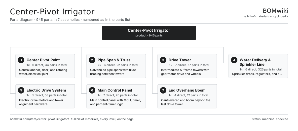
| # | Part | Qty | What it does |
|---|---|---|---|
| 1 | Center Pivot Point 6 parts | 1× | Central anchor, riser, and rotating water/electrical joint |
| 2 | Pipe Span & Truss 6 parts | 7× | Galvanized pipe spans with truss bracing between towers |
| 3 | Drive Tower 7 parts | 6× | Intermediate A-frame towers with gearmotor drive and wheels |
| 4 | Water Delivery & Sprinkler Line 6 parts | 1× | Sprinkler drops, regulators, and end gun along the lateral |
| 5 | Electric Drive System 5 parts | 1× | Electric drive motors and tower alignment hardware |
| 6 | Main Control Panel 7 parts | 1× | Main control panel with MCU, timer, and percent-timer logic |
| 7 | End Overhang Boom 4 parts | 1× | Cantilevered end boom beyond the last drive tower |
3D model
No 3D model yet. Have a CAD file of this? Add a 3D model — STL renders right on this page; STEP, FreeCAD, and OpenSCAD sources are welcome too (openly licensed, like all 3D models on BOMwiki).
Build & assembly graph
expand / collapse · shared sub-assemblies converge · links to related products · est. labourTap an assembly to expand/collapse · tap a part to open it · use “Open page” for any node · drag to pan, scroll to zoom.
Bill of materials for Center-Pivot Irrigator
7 top-level lines · 82 rows shown · 945 parts total · indented to 3 levels| # | Item / sub-assembly | Part no. | Qty/assy | Ext. qty | Parts | Type |
|---|---|---|---|---|---|---|
| 1 | Center Pivot Point 6 parts | center-pivot-irrigator-pivot-point | 1× | 1 | 34 | assembly |
| 1.1 | Pivot Base Frame 3 parts | center-pivot-irrigator-pivot-base | 1× | 1 | 9 | assembly |
| 1.1.1 | Pivot Base Leg | center-pivot-irrigator-base-legs | 4× | 4 | · | part |
| 1.1.2 | Riser Support Collar | center-pivot-irrigator-base-collar | 1× | 1 | · | part |
| 1.1.3 | Foundation Anchor Plate | center-pivot-irrigator-anchor-plate | 4× | 4 | · | part |
| 1.2 | Pivot Riser Pipe | center-pivot-irrigator-pivot-riser | 1× | 1 | · | part |
| 1.3 | Collector Ring (Slip Ring) 4 parts | center-pivot-irrigator-collector-ring | 1× | 1 | 21 | assembly |
| 1.3.1 | Slip Ring Conductor Disc | center-pivot-irrigator-slip-ring-disc | 6× | 6 | · | part |
| 1.3.2 | Collector Carbon Brush | center-pivot-irrigator-carbon-brush | 12× | 12 | · | part |
| 1.3.3 | Wire Bundle | wire-bundle | 1× | 1 | · | part |
| 1.3.4 | Oil Seal | oil-seal | 2× | 2 | · | part |
| 1.4 | Rotary Water Union | center-pivot-irrigator-swivel-joint | 1× | 1 | · | part |
| 1.5 | Pivot Turntable Bearing | center-pivot-irrigator-pivot-bearing | 1× | 1 | · | part |
| 1.6 | Fastener Set | fastener-set | 1× | 1 | · | part |
| 2 | Pipe Span & Truss 6 parts | center-pivot-irrigator-span-structure | 7× | 7 | 22 | assembly |
| 2.1 | Galvanized Span Pipe | center-pivot-irrigator-span-pipe | 1× | 7 | · | part |
| 2.2 | Span Truss Rod | center-pivot-irrigator-truss-rod | 4× | 28 | · | part |
| 2.3 | Truss Diagonal Strut | center-pivot-irrigator-truss-strut | 6× | 42 | · | part |
| 2.4 | Span Flex Coupler | center-pivot-irrigator-span-coupler | 2× | 14 | · | part |
| 2.5 | Truss U-Bolt Clamp | center-pivot-irrigator-truss-clamp | 8× | 56 | · | part |
| 2.6 | Fastener Set | fastener-set | 1× | 7 | · | part |
| 3 | Drive Tower 7 parts | center-pivot-irrigator-drive-tower | 6× | 6 | 57 | assembly |
| 3.1 | Tower A-Frame | center-pivot-irrigator-tower-frame | 1× | 6 | · | part |
| 3.2 | Tower Gearmotor 6 parts | center-pivot-irrigator-tower-gearmotor | 1× | 6 | 32 | assembly |
| 3.2.1 | Stator Assembly 3 parts + deeper › | stator-assembly | 1× | 6 | 3 | assembly |
| 3.2.2 | Rotor Assembly 4 parts + deeper › | rotor-assembly | 1× | 6 | 19 | assembly |
| 3.2.3 | Helical Gear Pair | gear-pair | 2× | 12 | · | part |
| 3.2.4 | Gearbox Housing | gearbox-housing | 1× | 6 | · | part |
| 3.2.5 | Ball Bearing | ball-bearing | 4× | 24 | · | part |
| 3.2.6 | Oil Seal | oil-seal | 3× | 18 | · | part |
| 3.3 | Wheel Gearbox 5 parts | center-pivot-irrigator-wheel-gearbox | 2× | 12 | 9 | assembly |
| 3.3.1 | Helical Gear Pair | gear-pair | 2× | 24 | · | part |
| 3.3.2 | Gearbox Housing | gearbox-housing | 1× | 12 | · | part |
| 3.3.3 | Ball Bearing | ball-bearing | 3× | 36 | · | part |
| 3.3.4 | Oil Seal | oil-seal | 2× | 24 | · | part |
| 3.3.5 | O-Ring Set | oring-set | 1× | 12 | · | part |
| 3.4 | Tower Wheel & Tire | center-pivot-irrigator-tower-wheel | 2× | 12 | · | part |
| 3.5 | Tower Driveshaft | center-pivot-irrigator-driveshaft | 2× | 12 | · | part |
| 3.6 | Tower Alignment Switch | center-pivot-irrigator-alignment-switch | 1× | 6 | · | part |
| 3.7 | Fastener Set | fastener-set | 1× | 6 | · | part |
| 4 | Water Delivery & Sprinkler Line 6 parts | center-pivot-irrigator-sprinkler-line | 1× | 1 | 325 | assembly |
| 4.1 | Sprinkler Head | center-pivot-irrigator-sprinkler-head | 80× | 80 | · | part |
| 4.2 | Drop Tube & Hose | center-pivot-irrigator-drop-tube | 80× | 80 | · | part |
| 4.3 | Pressure Regulator | center-pivot-irrigator-pressure-regulator | 80× | 80 | · | part |
| 4.4 | Gooseneck Outlet | center-pivot-irrigator-gooseneck | 80× | 80 | · | part |
| 4.5 | End Gun Assembly 4 parts | center-pivot-irrigator-end-gun | 1× | 1 | 4 | assembly |
| 4.5.1 | End-Gun Nozzle | center-pivot-irrigator-gun-nozzle | 1× | 1 | · | part |
| 4.5.2 | End-Gun Body | center-pivot-irrigator-gun-body | 1× | 1 | · | part |
| 4.5.3 | End-Gun Solenoid Valve | center-pivot-irrigator-gun-valve | 1× | 1 | · | part |
| 4.5.4 | Coil Spring | coil-spring | 1× | 1 | · | part |
| 4.6 | End-Gun Booster Pump | center-pivot-irrigator-booster-pump | 1× | 1 | · | part |
| 5 | Electric Drive System 5 parts | center-pivot-irrigator-drive-system | 1× | 1 | 58 | assembly |
| 5.1 | Span Power Cable | center-pivot-irrigator-span-cable | 7× | 7 | · | part |
| 5.2 | Tower Junction Box 4 parts | center-pivot-irrigator-tower-box | 6× | 6 | 5 | assembly |
| 5.2.1 | Tower Box Enclosure | center-pivot-irrigator-tower-box-shell | 1× | 6 | · | part |
| 5.2.2 | Relay | relay | 1× | 6 | · | part |
| 5.2.3 | Wire Bundle | wire-bundle | 1× | 6 | · | part |
| 5.2.4 | Connector | connector | 2× | 12 | · | part |
| 5.3 | Relay | relay | 6× | 6 | · | part |
| 5.4 | Connector | connector | 14× | 14 | · | part |
| 5.5 | Pressure Sensor | pressure-sensor | 1× | 1 | · | part |
| 6 | Main Control Panel 7 parts | center-pivot-irrigator-control-panel | 1× | 1 | 20 | assembly |
| 6.1 | Controller Board 5 parts | center-pivot-irrigator-controller-pcb | 1× | 1 | 9 | assembly |
| 6.1.1 | Bare PCB | pcb-bare | 1× | 1 | · | part |
| 6.1.2 | Microcontroller | mcu | 1× | 1 | · | part |
| 6.1.3 | SMD Passive (R/C/L) | smd-passives | 1× | 1 | · | part |
| 6.1.4 | Relay | relay | 2× | 2 | · | part |
| 6.1.5 | Connector | connector | 4× | 4 | · | part |
| 6.2 | LCD Panel | lcd-panel | 1× | 1 | · | part |
| 6.3 | Power Supply | power-supply | 1× | 1 | · | part |
| 6.4 | Percent Timer | center-pivot-irrigator-percent-timer | 1× | 1 | · | part |
| 6.5 | Relay | relay | 4× | 4 | · | part |
| 6.6 | Safety Interlock Circuit 3 parts | center-pivot-irrigator-safety-circuit | 1× | 1 | 3 | assembly |
| 6.6.1 | Pressure Sensor | pressure-sensor | 1× | 1 | · | part |
| 6.6.2 | Relay | relay | 1× | 1 | · | part |
| 6.6.3 | Wire Bundle | wire-bundle | 1× | 1 | · | part |
| 6.7 | Wire Bundle | wire-bundle | 1× | 1 | · | part |
| 7 | End Overhang Boom 4 parts | center-pivot-irrigator-end-overhang | 1× | 1 | 12 | assembly |
| 7.1 | Overhang Pipe | center-pivot-irrigator-overhang-pipe | 1× | 1 | · | part |
| 7.2 | Overhang Stay Cable | center-pivot-irrigator-cable-stay | 2× | 2 | · | part |
| 7.3 | Overhang King Post | center-pivot-irrigator-king-post | 1× | 1 | · | part |
| 7.4 | Sprinkler Head | center-pivot-irrigator-sprinkler-head | 8× | 8 | · | part |
Related products
same domain, ranked by shared parts Mobile Grain Dryer
554 parts · shares 21 with this page
Mobile Grain Dryer
554 parts · shares 21 with this page
 Lateral Move Irrigation Machine
1,054 parts · shares 20 with this page
Lateral Move Irrigation Machine
1,054 parts · shares 20 with this page
 Robotic Milking System
153 parts · shares 18 with this page
Robotic Milking System
153 parts · shares 18 with this page
 Articulated Tractor
1,229 parts · shares 20 with this page
Articulated Tractor
1,229 parts · shares 20 with this page
 Large Round Baler
783 parts · shares 20 with this page
Large Round Baler
783 parts · shares 20 with this page
 Orchard Tractor
562 parts · shares 20 with this page
Orchard Tractor
562 parts · shares 20 with this page
Sourcing: possible vendors
Prices, MOQ, and lead times are algorithmic estimates, not quotes, and not claims about these companies. Company mappings are curated by keyword; est. price band $5k–$800k. How estimates work| Vendor | HQ | Specialty | MOQ | Lead time |
|---|---|---|---|---|
| deere.com ↗ | Moline, US | Agriculture & turf | made to order | 14–24 wks |
| cnh.com ↗ | Basildon, GB | Agriculture (Case IH, New Holland) | made to order | 14–24 wks |
|
🇺🇸AGCO
agcocorp.com ↗
|
Duluth, US | Agriculture (Fendt, Massey Ferguson) | made to order | 14–24 wks |
|
🇩🇪Claas
claas.com ↗
|
Harsewinkel, DE | Harvesters & tractors | made to order | 14–24 wks |
|
🇯🇵Kubota
kubota.com ↗
|
Osaka, JP | Compact tractors & equipment | made to order | 14–24 wks |
1,028-word article