Strip-Till Implement
ProductOverview
A strip-till implement tills and fertilizes only the narrow band where a row crop will be planted, leaving the soil between the rows undisturbed and covered with residue. It is a middle path between full tillage, which works the whole field but exposes soil to erosion and dries it out, and no-till, which leaves everything undisturbed but can leave the seed zone cold, wet, and cloddy in spring. By working a strip perhaps twenty centimetres wide for each row, strip-till warms and mellows just the seedbed, places fertilizer right in the root zone, and keeps the erosion protection and moisture of the undisturbed middles.
The tool is a wide Toolbar Frame carrying one Strip-Till Row Unit per crop row, fed by the Fertilizer System and managed from the cab through the Rate Monitor. It tows on the Tow Hitch, rides on the Transport Wheels in transport, and folds for the road.
The toolbar
The Toolbar Frame sets the geometry that the later planter must match exactly, since the planter will run its rows down the middle of these tilled strips. Its Main Toolbar carries the centre row units, and Fold Wing sections on each end carry the rest, raised for road transport by Fold Cylinder hydraulics. Each row unit fixes with a Row Clamp so spacing can be set to the same value the planter uses, and Sheet Metal Panel gussets stiffen the frame against the side loads of the shanks. Getting the spacing exact matters, because a strip even a few centimetres off line wastes the warming and the banded fertilizer when the planter cannot follow it.
The row unit
The Strip-Till Row Unit is where the real work happens, and it is a small sequence of tools that act on one strip in order. First a Residue Coulter slices through surface residue so nothing plugs the shank. Then a Row Cleaner, with its Cleaner Wheel pair on a Cleaner Arm, sweeps the residue and loose clods off the strip so the bare seed zone can warm and dry faster than the covered middles in spring.
Next the Mole Shank opens the strip. Its Shank Leg, tipped with a hard-faced Shank Point, cuts and lifts the soil to working depth and fractures any compaction in the row, while a Fertilizer Tube down its back drops fertilizer into the fractured zone below where the seed will sit. A Shear Bolt protects the unit if it strikes a rock. Behind the shank, a pair of Berming Disc angled discs pull the loosened soil back over the strip into a raised berm, and a Rolling Basket crumbles the clods and firms that berm into a clean, mellow seedbed strip. The whole unit rides on a Parallel Linkage loaded by a Coil Spring so it follows the ground contour while holding its depth.
Banding the fertilizer
Placing fertilizer in the strip during tillage is half the point of the machine, because a deep band in the root zone is taken up more efficiently than fertilizer broadcast across the whole surface. The Fertilizer System carries the supply in a Fertilizer Tank, doses it through a Metering Unit driven by a Servo Motor at a rate set per area, and a Fertilizer Pump feeds a Distribution Manifold that splits the flow evenly among the row delivery tubes, sealed throughout by an O-Ring Set. Each row's share runs down its shank tube into the fractured zone, so the nutrients sit where the roots will reach them rather than on the surface where they can wash off or volatilize.
Control and monitoring
The Rate Monitor in the cab ties the application together. Its Controller Board and Microcontroller drive the metering to the target rate, showing status on an LCD Panel, while a Flow Sensor confirms the actual fertilizer flow against the set rate. A Section Switch shuts off rows on headlands and where strips would overlap, so fertilizer is not double-applied, and the controller logs an as-applied record through its Connector harness. This rate control and section shutoff are what make strip-till a precision operation rather than just a narrow tillage pass.
Hitch, transport, and use
The implement tows on the Tow Hitch, whose Drawbar hooks to the tractor, with a Parking Jack for parking and Hose Coupler fittings for the hydraulics. In transport the wings fold and the Transport Wheels, with its Transport Wheel tires on Wheel Axle axles, carries the weight on the road.
Strip-till suits row crops such as maize, soybeans, sugar beet, and cotton on farms that want the soil conservation of reduced tillage without the cold, slow seedbeds that pure no-till can give in heavy or northern soils. The strips are often made in the fall and planted into the next spring, letting the berms settle and warm before planting, or made in a single pass just ahead of the planter where soil and season allow. The limits are that the strips must be made accurately and the planter guided to follow them, which usually means satellite guidance on both operations, and that on very stony ground the shanks trip and wear quickly. Where those conditions are met, strip-till cuts erosion and fuel use compared with full tillage while giving the warm, banded seed zone that a row crop needs.
Strip-Till Implement parts and their functions
6 top-level parts · 124 parts in total · full bill of materials below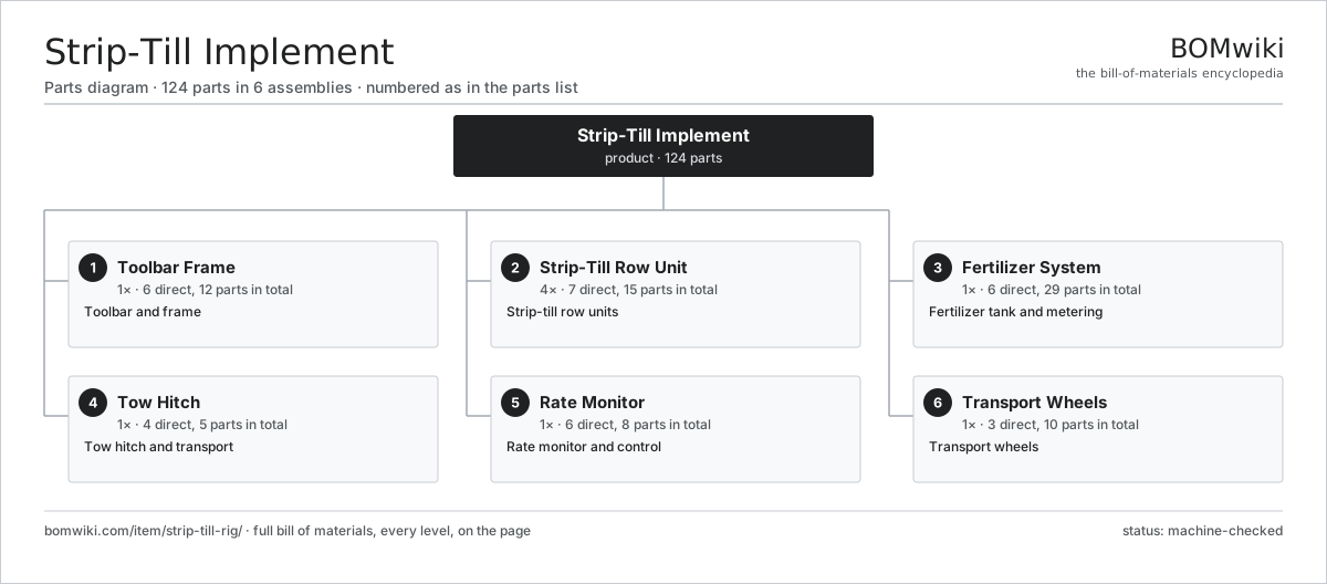
| # | Part | Qty | What it does |
|---|---|---|---|
| 1 | Toolbar Frame 6 parts | 1× | Toolbar and frame |
| 2 | Strip-Till Row Unit 7 parts | 4× | Strip-till row units |
| 3 | Fertilizer System 6 parts | 1× | Fertilizer tank and metering |
| 4 | Tow Hitch 4 parts | 1× | Tow hitch and transport |
| 5 | Rate Monitor 6 parts | 1× | Rate monitor and control |
| 6 | Transport Wheels 3 parts | 1× | Transport wheels |
3D model
No 3D model yet. Have a CAD file of this? Add a 3D model — STL renders right on this page; STEP, FreeCAD, and OpenSCAD sources are welcome too (openly licensed, like all 3D models on BOMwiki).
Build & assembly graph
expand / collapse · shared sub-assemblies converge · links to related products · est. labourTap an assembly to expand/collapse · tap a part to open it · use “Open page” for any node · drag to pan, scroll to zoom.
Bill of materials for Strip-Till Implement
6 top-level lines · 49 rows shown · 124 parts total · indented to 3 levels| # | Item / sub-assembly | Part no. | Qty/assy | Ext. qty | Parts | Type |
|---|---|---|---|---|---|---|
| 1 | Toolbar Frame 6 parts | strip-till-rig-toolbar | 1× | 1 | 12 | assembly |
| 1.1 | Main Toolbar | strip-till-rig-main-bar | 1× | 1 | · | part |
| 1.2 | Fold Wing | strip-till-rig-fold-wing | 2× | 2 | · | part |
| 1.3 | Fold Cylinder | strip-till-rig-fold-cylinder | 2× | 2 | · | part |
| 1.4 | Row Clamp | strip-till-rig-row-clamp | 4× | 4 | · | part |
| 1.5 | Sheet Metal Panel | sheet-panel | 2× | 2 | · | part |
| 1.6 | Fastener Set | fastener-set | 1× | 1 | · | part |
| 2 | Strip-Till Row Unit 7 parts | strip-till-rig-row-unit | 4× | 4 | 15 | assembly |
| 2.1 | Residue Coulter | strip-till-rig-residue-coulter | 1× | 4 | · | part |
| 2.2 | Row Cleaner 3 parts | strip-till-rig-row-cleaner | 1× | 4 | 5 | assembly |
| 2.2.1 | Cleaner Wheel | strip-till-rig-cleaner-wheel | 2× | 8 | · | part |
| 2.2.2 | Cleaner Arm | strip-till-rig-cleaner-arm | 1× | 4 | · | part |
| 2.2.3 | Ball Bearing | ball-bearing | 2× | 8 | · | part |
| 2.3 | Mole Shank 4 parts | strip-till-rig-mole-shank | 1× | 4 | 4 | assembly |
| 2.3.1 | Shank Leg | strip-till-rig-shank-leg | 1× | 4 | · | part |
| 2.3.2 | Shank Point | strip-till-rig-shank-point | 1× | 4 | · | part |
| 2.3.3 | Fertilizer Tube | strip-till-rig-fert-tube | 1× | 4 | · | part |
| 2.3.4 | Shear Bolt | strip-till-rig-shear-bolt | 1× | 4 | · | part |
| 2.4 | Berming Disc | strip-till-rig-berm-disc | 2× | 8 | · | part |
| 2.5 | Rolling Basket | strip-till-rig-rolling-basket | 1× | 4 | · | part |
| 2.6 | Parallel Linkage | strip-till-rig-parallel-linkage | 1× | 4 | · | part |
| 2.7 | Coil Spring | coil-spring | 1× | 4 | · | part |
| 3 | Fertilizer System 6 parts | strip-till-rig-fertilizer-system | 1× | 1 | 29 | assembly |
| 3.1 | Fertilizer Tank | strip-till-rig-fert-tank | 1× | 1 | · | part |
| 3.2 | Metering Unit | strip-till-rig-metering-unit | 1× | 1 | · | part |
| 3.3 | Distribution Manifold | strip-till-rig-distribution-manifold | 1× | 1 | · | part |
| 3.4 | Fertilizer Pump | strip-till-rig-fert-pump | 1× | 1 | · | part |
| 3.5 | Servo Motor 4 parts | servo-motor | 1× | 1 | 24 | assembly |
| 3.5.1 | Stator Assembly 3 parts + deeper › | stator-assembly | 1× | 1 | 3 | assembly |
| 3.5.2 | Rotor Assembly 4 parts + deeper › | rotor-assembly | 1× | 1 | 19 | assembly |
| 3.5.3 | Encoder | encoder | 1× | 1 | · | part |
| 3.5.4 | Motor Housing | motor-housing | 1× | 1 | · | part |
| 3.6 | O-Ring Set | oring-set | 1× | 1 | · | part |
| 4 | Tow Hitch 4 parts | strip-till-rig-hitch | 1× | 1 | 5 | assembly |
| 4.1 | Drawbar | strip-till-rig-drawbar | 1× | 1 | · | part |
| 4.2 | Parking Jack | strip-till-rig-hitch-jack | 1× | 1 | · | part |
| 4.3 | Hose Coupler | strip-till-rig-hose-coupler | 2× | 2 | · | part |
| 4.4 | Fastener Set | fastener-set | 1× | 1 | · | part |
| 5 | Rate Monitor 6 parts | strip-till-rig-monitor | 1× | 1 | 8 | assembly |
| 5.1 | Controller Board | strip-till-rig-monitor-pcb | 1× | 1 | · | part |
| 5.2 | Microcontroller | mcu | 1× | 1 | · | part |
| 5.3 | LCD Panel | lcd-panel | 1× | 1 | · | part |
| 5.4 | Flow Sensor | strip-till-rig-flow-sensor | 1× | 1 | · | part |
| 5.5 | Section Switch | strip-till-rig-section-switch | 1× | 1 | · | part |
| 5.6 | Connector | connector | 3× | 3 | · | part |
| 6 | Transport Wheels 3 parts | strip-till-rig-wheel-set | 1× | 1 | 10 | assembly |
| 6.1 | Transport Wheel | strip-till-rig-transport-wheel | 4× | 4 | · | part |
| 6.2 | Wheel Axle | strip-till-rig-axle | 2× | 2 | · | part |
| 6.3 | Ball Bearing | ball-bearing | 4× | 4 | · | part |
Related products
same domain, ranked by shared parts Large Round Baler
783 parts · shares 15 with this page
Large Round Baler
783 parts · shares 15 with this page
 Agricultural Spray Drone
721 parts · shares 14 with this page
Agricultural Spray Drone
721 parts · shares 14 with this page
 Robotic Milking System
153 parts · shares 14 with this page
Laser Land Leveler
66 parts · shares 13 with this page
Robotic Milking System
153 parts · shares 14 with this page
Laser Land Leveler
66 parts · shares 13 with this page
 Mobile Grain Dryer
554 parts · shares 13 with this page
Mobile Grain Dryer
554 parts · shares 13 with this page
 Articulated Tractor
1,229 parts · shares 12 with this page
Articulated Tractor
1,229 parts · shares 12 with this page
Sourcing: possible vendors
Prices, MOQ, and lead times are algorithmic estimates, not quotes, and not claims about these companies. Company mappings are curated by keyword; est. price band $5k–$800k. How estimates work| Vendor | HQ | Specialty | MOQ | Lead time |
|---|---|---|---|---|
| deere.com ↗ | Moline, US | Agriculture & turf | made to order | 14–24 wks |
| cnh.com ↗ | Basildon, GB | Agriculture (Case IH, New Holland) | made to order | 14–24 wks |
|
🇺🇸AGCO
agcocorp.com ↗
|
Duluth, US | Agriculture (Fendt, Massey Ferguson) | made to order | 14–24 wks |
|
🇩🇪Claas
claas.com ↗
|
Harsewinkel, DE | Harvesters & tractors | made to order | 14–24 wks |
|
🇯🇵Kubota
kubota.com ↗
|
Osaka, JP | Compact tractors & equipment | made to order | 14–24 wks |
1,000-word article