High-Clearance Crop Sprayer
ProductOverview
A self-propelled high-clearance crop sprayer applies herbicides, fungicides, insecticides and liquid fertilizer over a growing crop. Its defining feature is height: the whole machine rides on tall legs so the frame and tank clear standing corn, soybeans or cereals, and a wide folding boom carries nozzles across many rows in one pass. Compared with a trailed sprayer pulled behind a tractor, the self-propelled machine offers a dedicated chassis, a pressurized cab, full suspension and ground speeds to 25 km/h, which together cover large acreages in the narrow weather windows that spraying demands.
The machine combines three engineering problems: move a heavy tank across a field at speed without compacting wheel tracks or upsetting the boom, hold a precise application rate as speed and terrain vary, and protect the operator from the chemical being applied. Each maps to a major subsystem below.
High-Clearance Chassis
The High-Clearance Chassis is a welded Main Frame standing on four tall Drop Leg drops that lower each wheel motor below the frame, opening 1.2 to 1.8 m of crop clearance. Narrow Wheel Assembly units run between rows, and a hydraulic Track Width Adjuster slides the wheels in or out so the same machine fits 76 cm corn or wider beans. Major joints use a Fastener Set for field service. Keeping wheel tracks narrow and consistent matters because every pass crushes a strip of crop, so the chassis is laid out to reuse the same tramlines all season.
Powertrain
The Powertrain starts with a Tier-4 Diesel Engine of 130 to 260 kW. Rather than a mechanical transmission, a Hydrostatic Pump drives a Wheel Motor at each hub through a planetary Final Drive, giving stepless ground speed and permanent four-wheel drive. Hydrostatic drive lets the operator dial an exact spray speed and creep through wet spots without shifting. A Cooling Pack pack rejects engine, charge-air and hydraulic heat, and a Fuel Tank holds enough diesel for a full day.
Product System
The Product System mixes and delivers the spray. A baffled Solution Tank of 2000 to 6000 L holds the working solution, kept uniform by a jet Agitator. A hydraulic-driven centrifugal Product Pump draws through a Strainer and feeds the boom through chemical-resistant Product Plumbing. A lowered Induction Hopper hopper lets the operator load concentrate at ground level, where a venturi pulls it into the tank. A separate Rinse Tank of clean water flushes the system in the field so residue does not damage the next crop.
Spray Boom
The Spray Boom spreads the chemical across 24 to 40 m. A truss Boom Center Frame carries two folding Boom Wing sections, unfolded by Fold Cylinder units and folded back to legal transport width. A pendulum Boom Suspension isolates the boom from chassis pitch and roll, holding nozzle height steady because boom bounce is the main cause of uneven application. Along the boom, Nozzle Body turrets each hold several Spray Tip options and a check valve, grouped into segments controlled by a Section Valve.
Rate Control
The Rate Control System system keeps application uniform regardless of speed. A Rate Controller built around an Microcontroller reads a Flow Meter and a Pressure Sensor, then trims pump output to hold the target rate in litres per hectare as ground speed changes. A GNSS Receiver receiver feeds an in-cab In-Cab Terminal running guidance and automatic section control, which shuts off boom segments over already-sprayed ground or field boundaries to cut overlap and chemical waste.
Cab, Suspension and Electrical
The Operator Cab is sealed and pressurized through a Carbon Filter charcoal element so vapor stays out while the operator works. It holds an air-suspension Operator Seat, a control Control Armrest, and a Cab HVAC unit on a ROPS-rated Cab Shell.
The Wheel Suspension places a Trailing Arm and a Suspension Strut backed by a gas Accumulator and a Coil Spring at each corner, smoothing the ride so the boom stays level. The Electrical System system ties everything together with a CAN Wire Bundle, sealed Connector units, a Battery, an Alternator and field Lighting.
Use and Variants
Operators spray in early morning or evening calm to limit drift, often with autosteer following season-long tramlines so the same wheel tracks are reused all season and crop loss to wheelings stays low. Spray timing is tight: a fungicide or post-emergence herbicide has a narrow window, and a self-propelled machine covers far more ground per day than a trailed unit, which is why large farms and custom applicators favor them despite the higher cost. Variants run wider booms for flat broadacre fields, narrower booms and taller clearance for late-season corn, and dry-fertilizer or air-boom conversions for split nitrogen application. Common options include pulse-width-modulated nozzles for turn-compensation and individual nozzle control, foam markers, crop-height boom autoleveling that holds nozzle height to the canopy, weed-sensing cameras for spot spraying that cut chemical use, and dual product tanks for direct injection of a second chemical without pre-mixing.
High-Clearance Crop Sprayer parts and their functions
8 top-level parts · 235 parts in total · full bill of materials below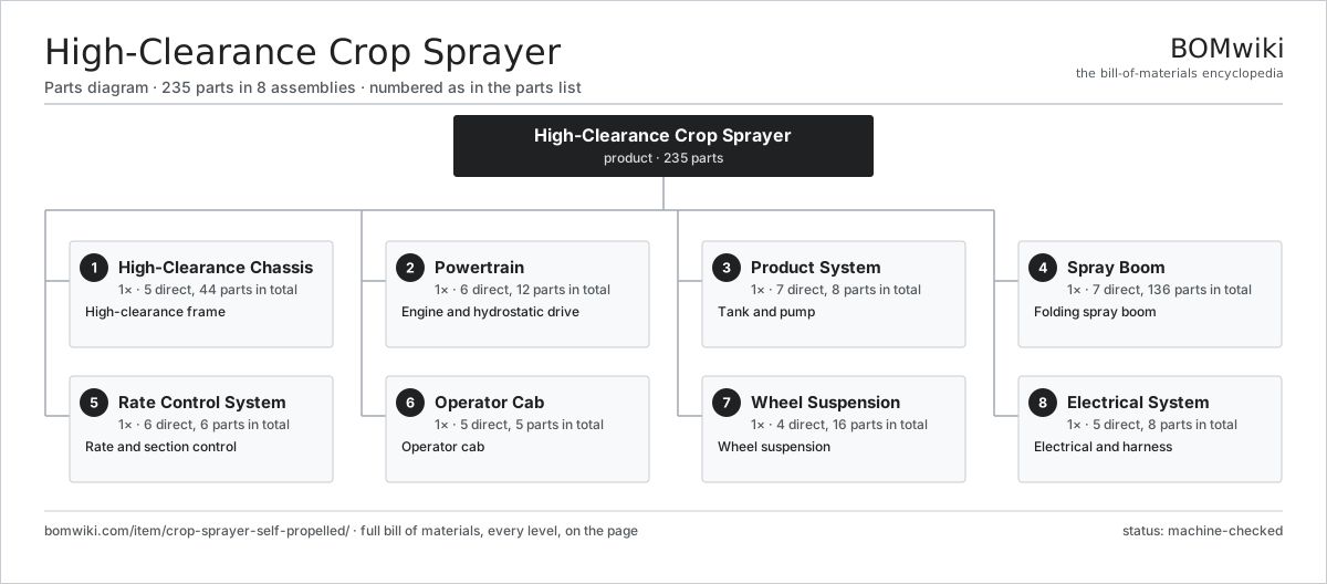
| # | Part | Qty | What it does |
|---|---|---|---|
| 1 | High-Clearance Chassis 5 parts | 1× | High-clearance frame |
| 2 | Powertrain 6 parts | 1× | Engine and hydrostatic drive |
| 3 | Product System 7 parts | 1× | Tank and pump |
| 4 | Spray Boom 7 parts | 1× | Folding spray boom |
| 5 | Rate Control System 6 parts | 1× | Rate and section control |
| 6 | Operator Cab 5 parts | 1× | Operator cab |
| 7 | Wheel Suspension 4 parts | 1× | Wheel suspension |
| 8 | Electrical System 5 parts | 1× | Electrical and harness |
3D model
No 3D model yet. Have a CAD file of this? Add a 3D model — STL renders right on this page; STEP, FreeCAD, and OpenSCAD sources are welcome too (openly licensed, like all 3D models on BOMwiki).
Build & assembly graph
expand / collapse · shared sub-assemblies converge · links to related products · est. labourTap an assembly to expand/collapse · tap a part to open it · use “Open page” for any node · drag to pan, scroll to zoom.
Bill of materials for High-Clearance Crop Sprayer
8 top-level lines · 58 rows shown · 235 parts total · indented to 3 levels| # | Item / sub-assembly | Part no. | Qty/assy | Ext. qty | Parts | Type |
|---|---|---|---|---|---|---|
| 1 | High-Clearance Chassis 5 parts | crop-sprayer-self-propelled-chassis | 1× | 1 | 44 | assembly |
| 1.1 | Main Frame | crop-sprayer-self-propelled-frame | 1× | 1 | · | part |
| 1.2 | Drop Leg | crop-sprayer-self-propelled-leg | 4× | 4 | · | part |
| 1.3 | Track Width Adjuster | crop-sprayer-self-propelled-track-adjust | 2× | 2 | · | part |
| 1.4 | Wheel Assembly 5 parts | wheel-assembly | 4× | 4 | 9 | assembly |
| 1.4.1 | Alloy Wheel | alloy-wheel | 1× | 4 | · | part |
| 1.4.2 | Tire | tire | 1× | 4 | · | part |
| 1.4.3 | TPMS Sensor | tpms-sensor | 1× | 4 | · | part |
| 1.4.4 | Lug Nut | lug-nut | 5× | 20 | · | part |
| 1.4.5 | Valve Stem | valve-stem | 1× | 4 | · | part |
| 1.5 | Fastener Set | fastener-set | 1× | 1 | · | part |
| 2 | Powertrain 6 parts | crop-sprayer-self-propelled-powertrain | 1× | 1 | 12 | assembly |
| 2.1 | Diesel Engine | crop-sprayer-self-propelled-engine | 1× | 1 | · | part |
| 2.2 | Hydrostatic Pump | crop-sprayer-self-propelled-hydrostat-pump | 1× | 1 | · | part |
| 2.3 | Wheel Motor | crop-sprayer-self-propelled-wheel-motor | 4× | 4 | · | part |
| 2.4 | Cooling Pack | crop-sprayer-self-propelled-cooling | 1× | 1 | · | part |
| 2.5 | Fuel Tank | crop-sprayer-self-propelled-fuel-tank | 1× | 1 | · | part |
| 2.6 | Final Drive | crop-sprayer-self-propelled-final-drive | 4× | 4 | · | part |
| 3 | Product System 7 parts | crop-sprayer-self-propelled-product-system | 1× | 1 | 8 | assembly |
| 3.1 | Solution Tank | crop-sprayer-self-propelled-solution-tank | 1× | 1 | · | part |
| 3.2 | Rinse Tank | crop-sprayer-self-propelled-rinse-tank | 1× | 1 | · | part |
| 3.3 | Product Pump | crop-sprayer-self-propelled-product-pump | 1× | 1 | · | part |
| 3.4 | Agitator | crop-sprayer-self-propelled-agitator | 1× | 1 | · | part |
| 3.5 | Strainer | crop-sprayer-self-propelled-strainer | 2× | 2 | · | part |
| 3.6 | Induction Hopper | crop-sprayer-self-propelled-induction | 1× | 1 | · | part |
| 3.7 | Product Plumbing | crop-sprayer-self-propelled-plumbing | 1× | 1 | · | part |
| 4 | Spray Boom 7 parts | crop-sprayer-self-propelled-boom | 1× | 1 | 136 | assembly |
| 4.1 | Boom Center Frame | crop-sprayer-self-propelled-boom-center | 1× | 1 | · | part |
| 4.2 | Boom Wing | crop-sprayer-self-propelled-boom-wing | 2× | 2 | · | part |
| 4.3 | Fold Cylinder | crop-sprayer-self-propelled-fold-cylinder | 4× | 4 | · | part |
| 4.4 | Boom Suspension | crop-sprayer-self-propelled-boom-suspension | 1× | 1 | · | part |
| 4.5 | Nozzle Body | crop-sprayer-self-propelled-nozzle-body | 60× | 60 | · | part |
| 4.6 | Spray Tip | crop-sprayer-self-propelled-spray-tip | 60× | 60 | · | part |
| 4.7 | Section Valve | crop-sprayer-self-propelled-section-valve | 8× | 8 | · | part |
| 5 | Rate Control System 6 parts | crop-sprayer-self-propelled-spray-control | 1× | 1 | 6 | assembly |
| 5.1 | Rate Controller | crop-sprayer-self-propelled-rate-controller | 1× | 1 | · | part |
| 5.2 | Flow Meter | crop-sprayer-self-propelled-flow-meter | 1× | 1 | · | part |
| 5.3 | Pressure Sensor | crop-sprayer-self-propelled-pressure-sensor | 1× | 1 | · | part |
| 5.4 | GNSS Receiver | crop-sprayer-self-propelled-gps | 1× | 1 | · | part |
| 5.5 | In-Cab Terminal | crop-sprayer-self-propelled-display | 1× | 1 | · | part |
| 5.6 | Microcontroller | mcu | 1× | 1 | · | part |
| 6 | Operator Cab 5 parts | crop-sprayer-self-propelled-cab | 1× | 1 | 5 | assembly |
| 6.1 | Cab Shell | crop-sprayer-self-propelled-cab-shell | 1× | 1 | · | part |
| 6.2 | Carbon Filter | crop-sprayer-self-propelled-cab-filter | 1× | 1 | · | part |
| 6.3 | Operator Seat | crop-sprayer-self-propelled-seat | 1× | 1 | · | part |
| 6.4 | Control Armrest | crop-sprayer-self-propelled-armrest | 1× | 1 | · | part |
| 6.5 | Cab HVAC | crop-sprayer-self-propelled-hvac | 1× | 1 | · | part |
| 7 | Wheel Suspension 4 parts | crop-sprayer-self-propelled-suspension | 1× | 1 | 16 | assembly |
| 7.1 | Trailing Arm | crop-sprayer-self-propelled-susp-arm | 4× | 4 | · | part |
| 7.2 | Suspension Strut | crop-sprayer-self-propelled-susp-cylinder | 4× | 4 | · | part |
| 7.3 | Accumulator | crop-sprayer-self-propelled-accumulator | 4× | 4 | · | part |
| 7.4 | Coil Spring | coil-spring | 4× | 4 | · | part |
| 8 | Electrical System 5 parts | crop-sprayer-self-propelled-electrical | 1× | 1 | 8 | assembly |
| 8.1 | Battery | crop-sprayer-self-propelled-battery | 1× | 1 | · | part |
| 8.2 | Alternator | crop-sprayer-self-propelled-alternator | 1× | 1 | · | part |
| 8.3 | Lighting | crop-sprayer-self-propelled-lighting | 1× | 1 | · | part |
| 8.4 | Wire Bundle | wire-bundle | 1× | 1 | · | part |
| 8.5 | Connector | connector | 4× | 4 | · | part |
Related products
same domain, ranked by shared parts Boom Sprayer
356 parts · shares 9 with this page
Boom Sprayer
356 parts · shares 9 with this page
 Fertilizer Spreader
164 parts · shares 9 with this page
Fertilizer Spreader
164 parts · shares 9 with this page
 Round Baler
208 parts · shares 9 with this page
Round Baler
208 parts · shares 9 with this page
 Seed Drill
327 parts · shares 9 with this page
Seed Drill
327 parts · shares 9 with this page
 Self-Propelled Sprayer
482 parts · shares 9 with this page
Self-Propelled Sprayer
482 parts · shares 9 with this page
 Silage Trailer
185 parts · shares 8 with this page
Silage Trailer
185 parts · shares 8 with this page
Sourcing: possible vendors
Prices, MOQ, and lead times are algorithmic estimates, not quotes, and not claims about these companies. Company mappings are curated by keyword; est. price band $5k–$800k. How estimates work| Vendor | HQ | Specialty | MOQ | Lead time |
|---|---|---|---|---|
| deere.com ↗ | Moline, US | Agriculture & turf | made to order | 14–24 wks |
| cnh.com ↗ | Basildon, GB | Agriculture (Case IH, New Holland) | made to order | 14–24 wks |
|
🇺🇸AGCO
agcocorp.com ↗
|
Duluth, US | Agriculture (Fendt, Massey Ferguson) | made to order | 14–24 wks |
|
🇩🇪Claas
claas.com ↗
|
Harsewinkel, DE | Harvesters & tractors | made to order | 14–24 wks |
|
🇯🇵Kubota
kubota.com ↗
|
Osaka, JP | Compact tractors & equipment | made to order | 14–24 wks |
1,015-word article