Feed Grinder Mixer
ProductOverview
The Feed Grinder Mixer is a tow-behind wagon that does two jobs in one pass: it grinds whole grain to a chosen particle size and blends that meal with forage and supplements into a finished livestock ration. A tractor supplies all the power through a 540 rpm power take-off, so the machine carries no engine of its own. The operator loads grain through the Loading System, the grain passes through the Hammermill Grinding Unit, ground meal blows up into the Mixing Tank Body, and a Weighing System weighs each ingredient as it goes in. When the batch is mixed, the Unload Auger places it in a bunk or trough. The whole wagon rides on a Running Gear tandem axle and is towed from a drawbar Drawbar Hitch.
How the hammermill grinds grain
Grinding happens by impact. The Hammer Rotor spins at roughly 3,200 rpm and carries 36 Swing Hammer pieces strung on four Hammer Pin Rod pins between six Rotor Disc Plate discs. The hammers are not bolted rigid; they swing free, so they fly out under centrifugal force during grinding and fold back if they strike a stone or a bolt. Grain enters through the Feed Control Gate, which meters the flow so the rotor stays loaded without bogging the PTO. Inside the Grinding Chamber, the hammers smash the kernels against the Breaker Plate surfaces and the Chamber Wear Liner walls.
Particle size is set entirely by the Grinding Screen, a curved perforated sheet seated in the Screen Cradle below the rotor. Meal stays in the chamber and keeps getting hit until a fragment is small enough to pass a screen hole. A 3/16 in screen makes a fine meal for young stock; a 3/4 in screen makes a coarse crack for cattle. Once the meal clears the screen, the Mill Discharge Fan on the rotor shaft develops airflow that lifts it through the Meal Discharge Tube into the top of the tank. The rotor turns on Ball Bearing supports, and the hammers are reversible, so each one is flipped to use all four corners before it is replaced.
How the tank mixes the ration
The Mixing Tank Body is a rolled steel Mix Tank Shell with a Tank Bottom Cone at the bottom that funnels feed back to the auger. Mixing is done by a single Vertical Mixing Auger standing in the center of the tank. Its Auger Flighting lifts feed from the cone up the Auger Center Tube and showers it out the top, so material is folded over on itself again and again. Over 8 to 12 minutes a full batch turns over enough times that ground grain, hay, and minerals reach a uniform blend with no layering.
Supplements go in through the Supplement Hopper, where a Metering Slide sets the dose of mineral or salt. The vertical auger is driven by the Mix Auger Gearbox, a right-angle bevel box that uses a Helical Gear Pair inside a Gearbox Housing running in Gearbox Oil and sealed by Oil Seal rings. Two Clean-Out Door panels let the operator empty and rinse the tank when switching from one ration to another.
Loading and unloading
The Swing-Away Loading Auger pivots out on its Swing Pivot Bearing to reach into a grain bin or truck box, and its Loading Auger Flight carries grain up to the mill inlet. A ground-level Pickup Hopper catches grain at the auger base. For forage rations, the Hay Bale Feed Table uses a Feed Drag Chain to drag small bales of hay into the tank so they grind and blend with the grain.
When the batch is ready, the Unload Auger takes over. Its Unload Auger Flight pushes the ration up the Unload Auger Tube to a swiveling Discharge Spout that aims feed into the bunk. The Unload Clutch starts and stops this auger on its own, so the operator can mix without unloading. For road travel the auger folds at the Auger Fold Hinge.
Drive train
All power enters through the PTO Driveline, a telescoping shaft with two Universal Joint crosses and a PTO Safety Shield guard. A Slip Clutch sits in the line; its Friction Disc plates slip if the mill jams, which protects the gears from shock. The Main Gearbox splits power to the hammermill and to the Jackshaft. The jackshaft carries Drive Sheave pulleys that drive the augers and fan through a Belt Drive of matched Drive Belt V-belts kept tight by a spring-loaded Idler Pulley. Bearings throughout the drive use standard Ball Bearing units.
Weighing and chassis
Accurate rations depend on the scale. Four Load Cell transducers sit under the tank mounts and feed a Load Cell Junction Box that sums their signals for the Scale Indicator in the cab. The indicator board carries a Microcontroller and an LCD Panel so the operator can watch each ingredient weight build to target. The wagon rolls on a Tandem Axle with a Walking Beam on each side that lets the wheels follow rough ground. A Parking Jack holds the tongue when parked. Auger folding and feed-gate position are run by Fold Cylinder hydraulics fed from the tractor remotes through a Hydraulic Control Valve, with a Pressure Sensor watching circuit pressure.
Feed Grinder Mixer parts and their functions
8 top-level parts · 368 parts in total · full bill of materials below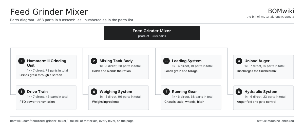
| # | Part | Qty | What it does |
|---|---|---|---|
| 1 | Hammermill Grinding Unit 7 parts | 1× | Grinds grain through a screen |
| 2 | Mixing Tank Body 8 parts | 1× | Holds and blends the ration |
| 3 | Loading System 4 parts | 1× | Loads grain and forage |
| 4 | Unload Auger 7 parts | 1× | Discharges the finished mix |
| 5 | Drive Train 7 parts | 1× | PTO power transmission |
| 6 | Weighing System 5 parts | 1× | Weighs ingredients |
| 7 | Running Gear 6 parts | 1× | Chassis, axle, wheels, hitch |
| 8 | Hydraulic System 6 parts | 1× | Auger fold and gate control |
3D model
No 3D model yet. Have a CAD file of this? Add a 3D model — STL renders right on this page; STEP, FreeCAD, and OpenSCAD sources are welcome too (openly licensed, like all 3D models on BOMwiki).
Build & assembly graph
expand / collapse · shared sub-assemblies converge · links to related products · est. labourTap an assembly to expand/collapse · tap a part to open it · use “Open page” for any node · drag to pan, scroll to zoom.
Bill of materials for Feed Grinder Mixer
8 top-level lines · 149 rows shown · 368 parts total · indented to 3 levels| # | Item / sub-assembly | Part no. | Qty/assy | Ext. qty | Parts | Type |
|---|---|---|---|---|---|---|
| 1 | Hammermill Grinding Unit 7 parts | feed-grinder-mixer-hammermill | 1× | 1 | 73 | assembly |
| 1.1 | Hammer Rotor 6 parts | feed-grinder-mixer-hammer-rotor | 1× | 1 | 54 | assembly |
| 1.1.1 | Rotor Shaft | feed-grinder-mixer-rotor-shaft | 1× | 1 | · | part |
| 1.1.2 | Rotor Disc Plate | feed-grinder-mixer-rotor-plate | 6× | 6 | · | part |
| 1.1.3 | Swing Hammer | feed-grinder-mixer-swing-hammer | 36× | 36 | · | part |
| 1.1.4 | Hammer Pin Rod | feed-grinder-mixer-hammer-rod | 4× | 4 | · | part |
| 1.1.5 | Rotor Spacer | feed-grinder-mixer-rotor-spacer | 5× | 5 | · | part |
| 1.1.6 | Ball Bearing | ball-bearing | 2× | 2 | · | part |
| 1.2 | Grinding Chamber 5 parts | feed-grinder-mixer-grinding-chamber | 1× | 1 | 7 | assembly |
| 1.2.1 | Chamber Housing | feed-grinder-mixer-chamber-housing | 1× | 1 | · | part |
| 1.2.2 | Breaker Plate | feed-grinder-mixer-breaker-plate | 2× | 2 | · | part |
| 1.2.3 | Screen Cradle | feed-grinder-mixer-screen-cradle | 1× | 1 | · | part |
| 1.2.4 | Chamber Wear Liner | feed-grinder-mixer-wear-liner | 2× | 2 | · | part |
| 1.2.5 | Fastener Set | fastener-set | 1× | 1 | · | part |
| 1.3 | Grinding Screen | feed-grinder-mixer-grinding-screen | 1× | 1 | · | part |
| 1.4 | Feed Control Gate 4 parts | feed-grinder-mixer-feed-gate | 1× | 1 | 4 | assembly |
| 1.4.1 | Gate Plate | feed-grinder-mixer-gate-plate | 1× | 1 | · | part |
| 1.4.2 | Gate Track | feed-grinder-mixer-gate-track | 1× | 1 | · | part |
| 1.4.3 | Gate Actuator | feed-grinder-mixer-gate-actuator | 1× | 1 | · | part |
| 1.4.4 | Fastener Set | fastener-set | 1× | 1 | · | part |
| 1.5 | Mill Discharge Fan 4 parts | feed-grinder-mixer-mill-fan | 1× | 1 | 4 | assembly |
| 1.5.1 | Fan Impeller | feed-grinder-mixer-fan-impeller | 1× | 1 | · | part |
| 1.5.2 | Fan Housing | feed-grinder-mixer-fan-housing | 1× | 1 | · | part |
| 1.5.3 | Meal Discharge Tube | feed-grinder-mixer-discharge-tube | 1× | 1 | · | part |
| 1.5.4 | Ball Bearing | ball-bearing | 1× | 1 | · | part |
| 1.6 | Ball Bearing | ball-bearing | 2× | 2 | · | part |
| 1.7 | Fastener Set | fastener-set | 1× | 1 | · | part |
| 2 | Mixing Tank Body 8 parts | feed-grinder-mixer-mix-tank | 1× | 1 | 28 | assembly |
| 2.1 | Mix Tank Shell | feed-grinder-mixer-tank-shell | 1× | 1 | · | part |
| 2.2 | Tank Bottom Cone | feed-grinder-mixer-tank-cone | 1× | 1 | · | part |
| 2.3 | Vertical Mixing Auger 5 parts | feed-grinder-mixer-vertical-auger | 1× | 1 | 8 | assembly |
| 2.3.1 | Auger Center Tube | feed-grinder-mixer-auger-tube | 1× | 1 | · | part |
| 2.3.2 | Auger Flighting | feed-grinder-mixer-auger-flighting | 1× | 1 | · | part |
| 2.3.3 | Auger Stub Shaft | feed-grinder-mixer-auger-stub-shaft | 2× | 2 | · | part |
| 2.3.4 | Ball Bearing | ball-bearing | 2× | 2 | · | part |
| 2.3.5 | Oil Seal | oil-seal | 2× | 2 | · | part |
| 2.4 | Mix Auger Gearbox 5 parts | feed-grinder-mixer-mix-gearbox | 1× | 1 | 9 | assembly |
| 2.4.1 | Gearbox Housing | gearbox-housing | 1× | 1 | · | part |
| 2.4.2 | Helical Gear Pair | gear-pair | 1× | 1 | · | part |
| 2.4.3 | Ball Bearing | ball-bearing | 4× | 4 | · | part |
| 2.4.4 | Oil Seal | oil-seal | 2× | 2 | · | part |
| 2.4.5 | Gearbox Oil | feed-grinder-mixer-gear-oil | 1× | 1 | · | part |
| 2.5 | Tank Top Lid | feed-grinder-mixer-tank-lid | 1× | 1 | · | part |
| 2.6 | Clean-Out Door | feed-grinder-mixer-clean-out-door | 2× | 2 | · | part |
| 2.7 | Supplement Hopper 4 parts | feed-grinder-mixer-supplement-hopper | 1× | 1 | 5 | assembly |
| 2.7.1 | Hopper Bin | feed-grinder-mixer-hopper-bin | 1× | 1 | · | part |
| 2.7.2 | Metering Slide | feed-grinder-mixer-metering-slide | 1× | 1 | · | part |
| 2.7.3 | Sheet Metal Panel | sheet-panel | 2× | 2 | · | part |
| 2.7.4 | Fastener Set | fastener-set | 1× | 1 | · | part |
| 2.8 | Fastener Set | fastener-set | 1× | 1 | · | part |
| 3 | Loading System 4 parts | feed-grinder-mixer-loading-system | 1× | 1 | 19 | assembly |
| 3.1 | Swing-Away Loading Auger 5 parts | feed-grinder-mixer-swing-auger | 1× | 1 | 6 | assembly |
| 3.1.1 | Loading Auger Tube | feed-grinder-mixer-load-auger-tube | 1× | 1 | · | part |
| 3.1.2 | Loading Auger Flight | feed-grinder-mixer-load-auger-flight | 1× | 1 | · | part |
| 3.1.3 | Swing Pivot Bearing | feed-grinder-mixer-swing-pivot | 1× | 1 | · | part |
| 3.1.4 | Ball Bearing | ball-bearing | 2× | 2 | · | part |
| 3.1.5 | Oil Seal | oil-seal | 1× | 1 | · | part |
| 3.2 | Pickup Hopper | feed-grinder-mixer-pickup-hopper | 1× | 1 | · | part |
| 3.3 | Hay Bale Feed Table 4 parts | feed-grinder-mixer-bale-table | 1× | 1 | 11 | assembly |
| 3.3.1 | Feed Table Frame | feed-grinder-mixer-table-frame | 1× | 1 | · | part |
| 3.3.2 | Feed Drag Chain | feed-grinder-mixer-feed-chain | 2× | 2 | · | part |
| 3.3.3 | Table Roller | feed-grinder-mixer-table-roller | 4× | 4 | · | part |
| 3.3.4 | Ball Bearing | ball-bearing | 4× | 4 | · | part |
| 3.4 | Fastener Set | fastener-set | 1× | 1 | · | part |
| 4 | Unload Auger 7 parts | feed-grinder-mixer-unload-auger | 1× | 1 | 15 | assembly |
| 4.1 | Unload Auger Tube | feed-grinder-mixer-unload-tube | 1× | 1 | · | part |
| 4.2 | Unload Auger Flight | feed-grinder-mixer-unload-flight | 1× | 1 | · | part |
| 4.3 | Discharge Spout | feed-grinder-mixer-unload-spout | 1× | 1 | · | part |
| 4.4 | Auger Fold Hinge | feed-grinder-mixer-fold-hinge | 1× | 1 | · | part |
| 4.5 | Unload Clutch 4 parts | feed-grinder-mixer-unload-clutch | 1× | 1 | 6 | assembly |
| 4.5.1 | Clutch Plate | feed-grinder-mixer-clutch-plate | 2× | 2 | · | part |
| 4.5.2 | Clutch Shift Fork | feed-grinder-mixer-clutch-fork | 1× | 1 | · | part |
| 4.5.3 | Coil Spring | coil-spring | 2× | 2 | · | part |
| 4.5.4 | Fastener Set | fastener-set | 1× | 1 | · | part |
| 4.6 | Ball Bearing | ball-bearing | 3× | 3 | · | part |
| 4.7 | Oil Seal | oil-seal | 2× | 2 | · | part |
| 5 | Drive Train 7 parts | feed-grinder-mixer-drive-train | 1× | 1 | 46 | assembly |
| 5.1 | PTO Driveline 4 parts | feed-grinder-mixer-pto-driveline | 1× | 1 | 6 | assembly |
| 5.1.1 | PTO Yoke | feed-grinder-mixer-pto-yoke | 2× | 2 | · | part |
| 5.1.2 | Universal Joint | feed-grinder-mixer-u-joint | 2× | 2 | · | part |
| 5.1.3 | PTO Telescoping Tube | feed-grinder-mixer-pto-tube | 1× | 1 | · | part |
| 5.1.4 | PTO Safety Shield | feed-grinder-mixer-pto-shield | 1× | 1 | · | part |
| 5.2 | Main Gearbox 5 parts | feed-grinder-mixer-main-gearbox | 1× | 1 | 13 | assembly |
| 5.2.1 | Gearbox Housing | gearbox-housing | 1× | 1 | · | part |
| 5.2.2 | Helical Gear Pair | gear-pair | 2× | 2 | · | part |
| 5.2.3 | Ball Bearing | ball-bearing | 6× | 6 | · | part |
| 5.2.4 | Oil Seal | oil-seal | 3× | 3 | · | part |
| 5.2.5 | Gearbox Oil | feed-grinder-mixer-gear-oil | 1× | 1 | · | part |
| 5.3 | Jackshaft 4 parts | feed-grinder-mixer-jackshaft | 1× | 1 | 7 | assembly |
| 5.3.1 | Jackshaft Shaft | feed-grinder-mixer-jackshaft-shaft | 1× | 1 | · | part |
| 5.3.2 | Drive Sheave | feed-grinder-mixer-drive-sheave | 3× | 3 | · | part |
| 5.3.3 | Ball Bearing | ball-bearing | 2× | 2 | · | part |
| 5.3.4 | Fastener Set | fastener-set | 1× | 1 | · | part |
| 5.4 | Belt Drive 4 parts | feed-grinder-mixer-belt-drive | 1× | 1 | 7 | assembly |
| 5.4.1 | Drive Belt | drive-belt | 3× | 3 | · | part |
| 5.4.2 | Idler Pulley | feed-grinder-mixer-idler-pulley | 2× | 2 | · | part |
| 5.4.3 | Belt Guard | feed-grinder-mixer-belt-guard | 1× | 1 | · | part |
| 5.4.4 | Coil Spring | coil-spring | 1× | 1 | · | part |
| 5.5 | Slip Clutch 4 parts | feed-grinder-mixer-slip-clutch | 1× | 1 | 8 | assembly |
| 5.5.1 | Friction Disc | feed-grinder-mixer-friction-disc | 2× | 2 | · | part |
| 5.5.2 | Coil Spring | coil-spring | 4× | 4 | · | part |
| 5.5.3 | Pressure Plate | feed-grinder-mixer-pressure-plate | 1× | 1 | · | part |
| 5.5.4 | Fastener Set | fastener-set | 1× | 1 | · | part |
| 5.6 | Ball Bearing | ball-bearing | 4× | 4 | · | part |
| 5.7 | Fastener Set | fastener-set | 1× | 1 | · | part |
| 6 | Weighing System 5 parts | feed-grinder-mixer-scale-system | 1× | 1 | 96 | assembly |
| 6.1 | Load Cell | feed-grinder-mixer-load-cell | 4× | 4 | · | part |
| 6.2 | Scale Indicator 5 parts | feed-grinder-mixer-scale-indicator | 1× | 1 | 84 | assembly |
| 6.2.1 | Bare PCB | pcb-bare | 1× | 1 | · | part |
| 6.2.2 | Microcontroller | mcu | 1× | 1 | · | part |
| 6.2.3 | LCD Panel | lcd-panel | 1× | 1 | · | part |
| 6.2.4 | SMD Passive (R/C/L) | smd-passives | 80× | 80 | · | part |
| 6.2.5 | Indicator Housing | feed-grinder-mixer-indicator-housing | 1× | 1 | · | part |
| 6.3 | Load Cell Junction Box | feed-grinder-mixer-junction-box | 1× | 1 | · | part |
| 6.4 | Wire Bundle | wire-bundle | 1× | 1 | · | part |
| 6.5 | Connector | connector | 6× | 6 | · | part |
| 7 | Running Gear 6 parts | feed-grinder-mixer-running-gear | 1× | 1 | 68 | assembly |
| 7.1 | Main Frame | feed-grinder-mixer-main-frame | 1× | 1 | · | part |
| 7.2 | Tandem Axle 5 parts | feed-grinder-mixer-tandem-axle | 1× | 1 | 20 | assembly |
| 7.2.1 | Axle Beam | feed-grinder-mixer-axle-beam | 2× | 2 | · | part |
| 7.2.2 | Walking Beam | feed-grinder-mixer-walking-beam | 2× | 2 | · | part |
| 7.2.3 | Wheel Spindle | feed-grinder-mixer-spindle | 4× | 4 | · | part |
| 7.2.4 | Ball Bearing | ball-bearing | 8× | 8 | · | part |
| 7.2.5 | Oil Seal | oil-seal | 4× | 4 | · | part |
| 7.3 | Tire & Wheel 3 parts | feed-grinder-mixer-wheel | 4× | 4 | 10 | assembly |
| 7.3.1 | Steel Rim | feed-grinder-mixer-rim | 1× | 4 | · | part |
| 7.3.2 | Implement Tire | feed-grinder-mixer-tire | 1× | 4 | · | part |
| 7.3.3 | Lug Nut | feed-grinder-mixer-lug-nut | 8× | 32 | · | part |
| 7.4 | Parking Jack 3 parts | feed-grinder-mixer-jack-stand | 1× | 1 | 3 | assembly |
| 7.4.1 | Jack Screw | feed-grinder-mixer-jack-screw | 1× | 1 | · | part |
| 7.4.2 | Jack Outer Tube | feed-grinder-mixer-jack-tube | 1× | 1 | · | part |
| 7.4.3 | Jack Crank Handle | feed-grinder-mixer-jack-crank | 1× | 1 | · | part |
| 7.5 | Drawbar Hitch 3 parts | feed-grinder-mixer-hitch | 1× | 1 | 3 | assembly |
| 7.5.1 | Drawbar | feed-grinder-mixer-drawbar | 1× | 1 | · | part |
| 7.5.2 | Hitch Clevis | feed-grinder-mixer-hitch-clevis | 1× | 1 | · | part |
| 7.5.3 | Hitch Pin | feed-grinder-mixer-hitch-pin | 1× | 1 | · | part |
| 7.6 | Fastener Set | fastener-set | 1× | 1 | · | part |
| 8 | Hydraulic System 6 parts | feed-grinder-mixer-hydraulics | 1× | 1 | 23 | assembly |
| 8.1 | Fold Cylinder 5 parts | feed-grinder-mixer-fold-cylinder | 2× | 2 | 5 | assembly |
| 8.1.1 | Cylinder Barrel | feed-grinder-mixer-cyl-barrel | 1× | 2 | · | part |
| 8.1.2 | Cylinder Rod | feed-grinder-mixer-cyl-rod | 1× | 2 | · | part |
| 8.1.3 | Cylinder Piston | feed-grinder-mixer-cyl-piston | 1× | 2 | · | part |
| 8.1.4 | O-Ring Set | oring-set | 1× | 2 | · | part |
| 8.1.5 | Oil Seal | oil-seal | 1× | 2 | · | part |
| 8.2 | Hydraulic Control Valve | feed-grinder-mixer-control-valve | 1× | 1 | · | part |
| 8.3 | Hydraulic Hose | feed-grinder-mixer-hyd-hose | 6× | 6 | · | part |
| 8.4 | Quick Coupler | feed-grinder-mixer-quick-coupler | 4× | 4 | · | part |
| 8.5 | Pressure Sensor | pressure-sensor | 1× | 1 | · | part |
| 8.6 | O-Ring Set | oring-set | 1× | 1 | · | part |
Related products
same domain, ranked by shared parts Mobile Grain Dryer
554 parts · shares 13 with this page
Vineyard Harvester
1,301 parts · shares 12 with this page
Mobile Grain Dryer
554 parts · shares 13 with this page
Vineyard Harvester
1,301 parts · shares 12 with this page
 Large Round Baler
783 parts · shares 12 with this page
Large Round Baler
783 parts · shares 12 with this page
 Orchard Tractor
562 parts · shares 12 with this page
Orchard Tractor
562 parts · shares 12 with this page
 Self-Propelled Potato Harvester
314 parts · shares 12 with this page
Self-Propelled Potato Harvester
314 parts · shares 12 with this page
 Feed Mixer Wagon
133 parts · shares 11 with this page
Feed Mixer Wagon
133 parts · shares 11 with this page
Sourcing: possible vendors
Prices, MOQ, and lead times are algorithmic estimates, not quotes, and not claims about these companies. Company mappings are curated by keyword; est. price band $5k–$800k. How estimates work| Vendor | HQ | Specialty | MOQ | Lead time |
|---|---|---|---|---|
| deere.com ↗ | Moline, US | Agriculture & turf | made to order | 14–24 wks |
| cnh.com ↗ | Basildon, GB | Agriculture (Case IH, New Holland) | made to order | 14–24 wks |
|
🇺🇸AGCO
agcocorp.com ↗
|
Duluth, US | Agriculture (Fendt, Massey Ferguson) | made to order | 14–24 wks |
|
🇩🇪Claas
claas.com ↗
|
Harsewinkel, DE | Harvesters & tractors | made to order | 14–24 wks |
|
🇯🇵Kubota
kubota.com ↗
|
Osaka, JP | Compact tractors & equipment | made to order | 14–24 wks |
1,031-word article