Silage Bagging Machine
ProductOverview
A silage bagging machine packs chopped forage into a long tube of polyethylene film so it can ferment and store in the open without a silo or bunker. Trucks and wagons tip their loads into the Hopper Assembly, a powered Rotor & Feed Assembly grabs the forage and compresses it, and the packed column pushes a continuous Tunnel & Bag Holder Assembly off the machine as a sealed bag that can reach 300 ft long. One machine handles 120 to 250 tons per hour, which lets a single bagger keep pace with several chopping crews during a short harvest window.
The principle is simple to state and hard to do well: pack the forage tight enough to drive out air, hold that density evenly along the whole bag, and seal the film so fermentation stays anaerobic. Density is the variable that decides feed quality. Too loose and trapped air spoils the crop; too tight and the film splits. The whole machine is built around controlling that one number.
How the bagging works
Forage arriving in the Hopper Assembly sits on a powered Hopper Floor Chain that walks it forward onto the Feed Table. From there the Feed Drag Chain drags it into the rotor. The Rotor Drum spins with 48 bolt-on Rotor Tooth units that bite the crop and force it through the Compression Chamber into the bag. Because the rotor packs against material that is already in the bag, the forage has nowhere to go but tight, and the reaction pushes the whole machine backward.
That backward push is what forms the bag. A folded plastic bag sits concertina-style on the Bag Cradle, sleeved over the Tunnel Shell and held by sprung Bag Retaining Finger retainers. As the silage column grows, the machine creeps forward and feeds bag film off the tunnel. The faster the rotor packs, the harder the machine wants to advance, so resisting that advance is exactly how density is set.
Density and braking
The machine is held back by a Brake & Density Assembly. Two Brake Cable runs anchor to the trailing end of the bag and wind onto a Cable Drum on each side. As packing pressure tries to drive the machine forward, the cables resist, and a Brake Disc on the transport axle is clamped by a hydraulic Brake Caliper. Heavier braking means denser silage.
The operator does not guess at the clamp force. A pair of Density Sensing Arm sensors ride against the silage column and feed the Density Control Valve, which sets caliper pressure through a hydraulic valve. A Pressure Sensor reads the actual brake line pressure so the reading on the LCD Panel reflects real packing force. Once the operator dials in a target, the system holds it as ground conditions and crop flow change.
Drive system
Most baggers run off a tractor through a telescoping PTO Drive Shaft turning at 540 or 1000 rpm. The shaft feeds a right-angle Reduction Gearbox that steps speed down to rotor range and multiplies torque. A roller Rotor Drive Chain then carries that torque to the rotor sprocket, kept tight by a sprung Chain Tensioner. A Overrun Shear Clutch protects the driveline with a shear element and a freewheel, and a Rotor Flywheel smooths the cyclic load as each batch of teeth bites into the crop. Self-powered models swap the PTO for an onboard diesel but keep the same gearbox and chain path.
A PTO-driven Hydraulic Gear Pump supplies the rest of the machine from a Hydraulic Reservoir. Three Hydraulic Cylinder rams handle tunnel lift and steering, the orbital Floor Chain Hydraulic Motor drives the hopper floor, and the brake calipers draw from the same circuit.
Materials and construction
The structural load path is heavy. The Main Frame is welded S355 box section, the Rotor Shaft is forged 42CrMo4, and the rotor teeth are abrasion-resistant Hardox plate because chopped corn carries grit and sand. The rotor turns in greased Ball Bearing units behind Oil Seal shields to keep crop juice and dust out. The Tunnel Shell is rolled S275 sheet sized to the bag diameter, since the tunnel sets the finished bag at 8, 9 or 10 ft across.
The whole machine rolls on four wide Transport Wheel flotation units carried on a box-section Transport Axle. Low tyre pressure spreads the 11,000 to 15,000 lb machine weight so it does not rut the bagging pad.
Variants and use
Baggers are sized by bag diameter. A 9 ft machine is the common dairy size, holding roughly 200 tons in a 200 ft bag, while 10 ft and 12 ft machines suit large feedlots and contractors. Smaller 6 to 8 ft units bag high-moisture grain and small-farm forage.
In the field the bagger parks on a firm level pad, the crew sleeves a bag, and chopping wagons feed the hopper continuously. The operator stands on the Operator Platform watching density on the display and trimming the Control Lever feed. When a bag is full the film is tied off and the next bag is sleeved, so a crew can run bag after bag through a harvest day with no fixed storage to fill or empty.
Silage Bagging Machine parts and their functions
8 top-level parts · 672 parts in total · full bill of materials below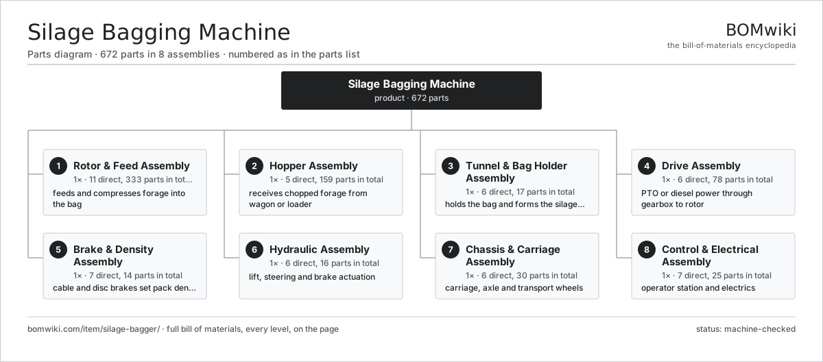
| # | Part | Qty | What it does |
|---|---|---|---|
| 1 | Rotor & Feed Assembly 11 parts | 1× | feeds and compresses forage into the bag |
| 2 | Hopper Assembly 5 parts | 1× | receives chopped forage from wagon or loader |
| 3 | Tunnel & Bag Holder Assembly 6 parts | 1× | holds the bag and forms the silage column |
| 4 | Drive Assembly 6 parts | 1× | PTO or diesel power through gearbox to rotor |
| 5 | Brake & Density Assembly 7 parts | 1× | cable and disc brakes set pack density |
| 6 | Hydraulic Assembly 6 parts | 1× | lift, steering and brake actuation |
| 7 | Chassis & Carriage Assembly 6 parts | 1× | carriage, axle and transport wheels |
| 8 | Control & Electrical Assembly 7 parts | 1× | operator station and electrics |
3D model
No 3D model yet. Have a CAD file of this? Add a 3D model — STL renders right on this page; STEP, FreeCAD, and OpenSCAD sources are welcome too (openly licensed, like all 3D models on BOMwiki).
Build & assembly graph
expand / collapse · shared sub-assemblies converge · links to related products · est. labourTap an assembly to expand/collapse · tap a part to open it · use “Open page” for any node · drag to pan, scroll to zoom.
Bill of materials for Silage Bagging Machine
8 top-level lines · 98 rows shown · 672 parts total · indented to 3 levels| # | Item / sub-assembly | Part no. | Qty/assy | Ext. qty | Parts | Type |
|---|---|---|---|---|---|---|
| 1 | Rotor & Feed Assembly 11 parts | silage-bagger-rotor-assy | 1× | 1 | 333 | assembly |
| 1.1 | Rotor Drum 3 parts | silage-bagger-rotor-drum | 1× | 1 | 51 | assembly |
| 1.1.1 | Drum Tube | silage-bagger-drum-tube | 1× | 1 | · | part |
| 1.1.2 | Drum End Plate | silage-bagger-drum-endplate | 2× | 2 | · | part |
| 1.1.3 | Tooth Mount Pocket | silage-bagger-tooth-mount | 48× | 48 | · | part |
| 1.2 | Rotor Tooth | silage-bagger-rotor-tooth | 48× | 48 | · | part |
| 1.3 | Rotor Shaft | silage-bagger-rotor-shaft | 1× | 1 | · | part |
| 1.4 | Ball Bearing | ball-bearing | 2× | 2 | · | part |
| 1.5 | Oil Seal | oil-seal | 2× | 2 | · | part |
| 1.6 | Rotor Bearing Housing | silage-bagger-bearing-housing | 2× | 2 | · | part |
| 1.7 | Feed Table | silage-bagger-feed-table | 1× | 1 | · | part |
| 1.8 | Feed Drag Chain 2 parts | silage-bagger-feed-chain | 2× | 2 | 110 | assembly |
| 1.8.1 | Conveyor Chain Link | silage-bagger-chain-link | 88× | 176 | · | part |
| 1.8.2 | Drag Chain Slat | silage-bagger-chain-slat | 22× | 44 | · | part |
| 1.9 | Feed Sprocket | silage-bagger-feed-sprocket | 4× | 4 | · | part |
| 1.10 | Compression Chamber | silage-bagger-compression-chamber | 1× | 1 | · | part |
| 1.11 | Fastener Set | fastener-set | 1× | 1 | · | part |
| 2 | Hopper Assembly 5 parts | silage-bagger-hopper-assy | 1× | 1 | 159 | assembly |
| 2.1 | Hopper Body | silage-bagger-hopper-body | 1× | 1 | · | part |
| 2.2 | Hopper Side Wing | silage-bagger-hopper-extension | 2× | 2 | · | part |
| 2.3 | Hopper Floor Chain 3 parts | silage-bagger-hopper-floor-chain | 1× | 1 | 154 | assembly |
| 2.3.1 | Conveyor Chain Link | silage-bagger-chain-link | 120× | 120 | · | part |
| 2.3.2 | Drag Chain Slat | silage-bagger-chain-slat | 30× | 30 | · | part |
| 2.3.3 | Feed Sprocket | silage-bagger-feed-sprocket | 4× | 4 | · | part |
| 2.4 | Floor Chain Hydraulic Motor | silage-bagger-hopper-hydraulic-motor | 1× | 1 | · | part |
| 2.5 | Fastener Set | fastener-set | 1× | 1 | · | part |
| 3 | Tunnel & Bag Holder Assembly 6 parts | silage-bagger-tunnel-assy | 1× | 1 | 17 | assembly |
| 3.1 | Tunnel Shell | silage-bagger-tunnel-shell | 1× | 1 | · | part |
| 3.2 | Bag Cradle | silage-bagger-bag-cradle | 1× | 1 | · | part |
| 3.3 | Bag Retaining Finger | silage-bagger-bag-finger | 8× | 8 | · | part |
| 3.4 | Density Sensing Arm | silage-bagger-density-arm | 2× | 2 | · | part |
| 3.5 | Coil Spring | coil-spring | 4× | 4 | · | part |
| 3.6 | Fastener Set | fastener-set | 1× | 1 | · | part |
| 4 | Drive Assembly 6 parts | silage-bagger-drive-assy | 1× | 1 | 78 | assembly |
| 4.1 | PTO Drive Shaft | silage-bagger-pto-shaft | 1× | 1 | · | part |
| 4.2 | Reduction Gearbox 5 parts | silage-bagger-gearbox | 1× | 1 | 11 | assembly |
| 4.2.1 | Gearbox Housing | gearbox-housing | 1× | 1 | · | part |
| 4.2.2 | Helical Gear Pair | gear-pair | 2× | 2 | · | part |
| 4.2.3 | Ball Bearing | ball-bearing | 4× | 4 | · | part |
| 4.2.4 | Oil Seal | oil-seal | 3× | 3 | · | part |
| 4.2.5 | O-Ring Set | oring-set | 1× | 1 | · | part |
| 4.3 | Rotor Drive Chain 3 parts | silage-bagger-drive-chain | 1× | 1 | 63 | assembly |
| 4.3.1 | Conveyor Chain Link | silage-bagger-chain-link | 60× | 60 | · | part |
| 4.3.2 | Feed Sprocket | silage-bagger-feed-sprocket | 2× | 2 | · | part |
| 4.3.3 | Chain Tensioner | silage-bagger-chain-tensioner | 1× | 1 | · | part |
| 4.4 | Overrun Shear Clutch | silage-bagger-clutch | 1× | 1 | · | part |
| 4.5 | Rotor Flywheel | silage-bagger-flywheel | 1× | 1 | · | part |
| 4.6 | Fastener Set | fastener-set | 1× | 1 | · | part |
| 5 | Brake & Density Assembly 7 parts | silage-bagger-brake-assy | 1× | 1 | 14 | assembly |
| 5.1 | Brake Disc | silage-bagger-brake-disc | 2× | 2 | · | part |
| 5.2 | Brake Caliper | silage-bagger-brake-caliper | 2× | 2 | · | part |
| 5.3 | Brake Cable | silage-bagger-brake-cable | 2× | 2 | · | part |
| 5.4 | Cable Drum | silage-bagger-cable-drum | 2× | 2 | · | part |
| 5.5 | Density Control Valve 3 parts | silage-bagger-density-controller | 1× | 1 | 4 | assembly |
| 5.5.1 | Valve Manifold Block | silage-bagger-control-valve-block | 1× | 1 | · | part |
| 5.5.2 | Coil Spring | coil-spring | 2× | 2 | · | part |
| 5.5.3 | O-Ring Set | oring-set | 1× | 1 | · | part |
| 5.6 | Pressure Sensor | pressure-sensor | 1× | 1 | · | part |
| 5.7 | Fastener Set | fastener-set | 1× | 1 | · | part |
| 6 | Hydraulic Assembly 6 parts | silage-bagger-hydraulic-assy | 1× | 1 | 16 | assembly |
| 6.1 | Hydraulic Gear Pump | silage-bagger-hydraulic-pump | 1× | 1 | · | part |
| 6.2 | Hydraulic Reservoir 2 parts | silage-bagger-hydraulic-tank | 1× | 1 | 2 | assembly |
| 6.2.1 | Reservoir Shell | silage-bagger-tank-shell | 1× | 1 | · | part |
| 6.2.2 | Hydraulic Oil Filter | silage-bagger-oil-filter | 1× | 1 | · | part |
| 6.3 | Hydraulic Cylinder 3 parts | silage-bagger-hydraulic-cylinder | 3× | 3 | 3 | assembly |
| 6.3.1 | Cylinder Barrel | silage-bagger-cylinder-barrel | 1× | 3 | · | part |
| 6.3.2 | Cylinder Rod | silage-bagger-cylinder-rod | 1× | 3 | · | part |
| 6.3.3 | O-Ring Set | oring-set | 1× | 3 | · | part |
| 6.4 | Hydraulic Hose Set | silage-bagger-hose-set | 1× | 1 | · | part |
| 6.5 | Pressure Sensor | pressure-sensor | 1× | 1 | · | part |
| 6.6 | O-Ring Set | oring-set | 2× | 2 | · | part |
| 7 | Chassis & Carriage Assembly 6 parts | silage-bagger-chassis-assy | 1× | 1 | 30 | assembly |
| 7.1 | Main Frame | silage-bagger-main-frame | 1× | 1 | · | part |
| 7.2 | Transport Axle 4 parts | silage-bagger-axle | 1× | 1 | 17 | assembly |
| 7.2.1 | Axle Beam | silage-bagger-axle-beam | 1× | 1 | · | part |
| 7.2.2 | Wheel Hub | silage-bagger-hub | 4× | 4 | · | part |
| 7.2.3 | Ball Bearing | ball-bearing | 8× | 8 | · | part |
| 7.2.4 | Oil Seal | oil-seal | 4× | 4 | · | part |
| 7.3 | Transport Wheel 2 parts | silage-bagger-wheel | 4× | 4 | 2 | assembly |
| 7.3.1 | Wheel Rim | silage-bagger-rim | 1× | 4 | · | part |
| 7.3.2 | Flotation Tyre | silage-bagger-tyre | 1× | 4 | · | part |
| 7.4 | Tow Hitch | silage-bagger-hitch | 1× | 1 | · | part |
| 7.5 | Parking Jack Leg | silage-bagger-jack-leg | 2× | 2 | · | part |
| 7.6 | Fastener Set | fastener-set | 1× | 1 | · | part |
| 8 | Control & Electrical Assembly 7 parts | silage-bagger-control-assy | 1× | 1 | 25 | assembly |
| 8.1 | Operator Platform | silage-bagger-operator-platform | 1× | 1 | · | part |
| 8.2 | Control Box 6 parts | silage-bagger-control-box | 1× | 1 | 12 | assembly |
| 8.2.1 | Bare PCB | pcb-bare | 1× | 1 | · | part |
| 8.2.2 | Microcontroller | mcu | 1× | 1 | · | part |
| 8.2.3 | SMD Passive (R/C/L) | smd-passives | 1× | 1 | · | part |
| 8.2.4 | Relay | relay | 4× | 4 | · | part |
| 8.2.5 | Connector | connector | 4× | 4 | · | part |
| 8.2.6 | Power Supply | power-supply | 1× | 1 | · | part |
| 8.3 | LCD Panel | lcd-panel | 1× | 1 | · | part |
| 8.4 | Control Lever | silage-bagger-control-lever | 3× | 3 | · | part |
| 8.5 | Wire Bundle | wire-bundle | 1× | 1 | · | part |
| 8.6 | Connector | connector | 6× | 6 | · | part |
| 8.7 | Fastener Set | fastener-set | 1× | 1 | · | part |
Related products
same domain, ranked by shared parts Center-Pivot Irrigator
945 parts · shares 13 with this page
Center-Pivot Irrigator
945 parts · shares 13 with this page
 Mobile Grain Dryer
554 parts · shares 13 with this page
Mobile Grain Dryer
554 parts · shares 13 with this page
 Lateral Move Irrigation Machine
1,054 parts · shares 12 with this page
Lateral Move Irrigation Machine
1,054 parts · shares 12 with this page
 Robotic Milking System
153 parts · shares 10 with this page
Robotic Milking System
153 parts · shares 10 with this page
 Continuous Grain Dryer
254 parts · shares 10 with this page
Continuous Grain Dryer
254 parts · shares 10 with this page
 Pneumatic Seed Drill
458 parts · shares 10 with this page
Pneumatic Seed Drill
458 parts · shares 10 with this page
Sourcing: possible vendors
Prices, MOQ, and lead times are algorithmic estimates, not quotes, and not claims about these companies. Company mappings are curated by keyword; est. price band $5k–$800k. How estimates work| Vendor | HQ | Specialty | MOQ | Lead time |
|---|---|---|---|---|
| deere.com ↗ | Moline, US | Agriculture & turf | made to order | 14–24 wks |
| cnh.com ↗ | Basildon, GB | Agriculture (Case IH, New Holland) | made to order | 14–24 wks |
|
🇺🇸AGCO
agcocorp.com ↗
|
Duluth, US | Agriculture (Fendt, Massey Ferguson) | made to order | 14–24 wks |
|
🇩🇪Claas
claas.com ↗
|
Harsewinkel, DE | Harvesters & tractors | made to order | 14–24 wks |
|
🇯🇵Kubota
kubota.com ↗
|
Osaka, JP | Compact tractors & equipment | made to order | 14–24 wks |
925-word article