Manure Injection Toolbar
ProductOverview
A manure injection toolbar places liquid manure or slurry below the soil surface instead of spreading it on top. Surface spreading loses a large share of the nitrogen to the air as ammonia and leaves odor and runoff risk; injection cuts a shallow slot, lays the manure in it, and presses soil back over the top, so more nutrient stays in the root zone and less escapes. The toolbar mounts on the rear of a slurry tanker or behind a tractor fed by a drag hose, and a pump pushes manure through a distribution system to a row of injectors.
The hard problems are different from a dry fertilizer machine. Slurry contains solids, stones and fiber that plug small passages, the flow has to split evenly across a dozen or more outlets, and the injectors must open and seal soil while handling thousands of litres per hectare. Each maps to a subsystem below.
Toolbar Frame
The Toolbar Frame carries the injectors across the working width. A heavy Center Frame clamps the center units and the manure manifold, with Folding Wing sections on Fold Pivot hinges that fold for road transport. A Gauge Wheel set references the frame to the ground for even depth, and a Headland Wheel set carries the frame when it is raised at the headland. Units clamp along the frame with a Fastener Set to set row spacing.
Injection Unit
Each Injection Unit cuts, fills and closes in one pass. A sharp Coulter Disc turning on a Ball Bearing slices residue and opens a slot, an Injector Tine follows to guide the slot to depth, and a wear-resistant Outlet Nozzle nozzle releases manure into the slot bottom. A Closing Wheel then firms soil over the top to hold the manure down and cut odor and runoff. A Parallel Arm linkage keeps the opener angle constant through depth changes, a Down-Pressure Cylinder cylinder loads the unit into firm or dry ground, and a Coil Spring protects the unit when it strikes an obstruction.
Distribution System
The Distribution System system divides one large flow into many equal small flows, which is harder than it sounds with a solids-laden liquid. A Stone Trap settles out rocks first, then an inline Macerator chops solids and fiber so they pass without bridging. A spinning vertical Flow Splitter divides the stream equally among the outlets, fed from the tanker through a large-bore Supply Hose and out to each injector through a Feed Hose. Even splitting matters because an uneven distributor leaves some rows over-applied and others starved.
Flow Control
The Flow Control System system sets the application rate by area. A Transfer Pump moves slurry from the tanker, a magnetic Flow Meter measures the flow despite the solids, and a proportional Rate Valve trims it to hold the target volume per hectare as ground speed changes. A Pressure Sensor watches line pressure for blockage, and an optional Nutrient Sensor uses near-infrared light to estimate the nitrogen content of the slurry in real time, so the controller can apply by nutrient rather than by raw volume.
Hydraulics and Depth Control
The Hydraulic System system handles fold, lift and down-pressure. A Fold Cylinder pair folds the wings, a Lift Cylinder pair raises the frame at the headland, and a Valve Bank directs flow, with a Accumulator giving consistent injector down-pressure over rough ground. Seals come from an O-Ring Set.
The Depth Control System system holds injection depth across changing soil. A Depth Wheel set sets the mechanical depth, a Depth Sensor pair reports frame height, and a Depth Adjuster shifts all units to a new depth on the go when soil firmness changes.
Electronics and Hitch
The Monitoring Electronics tie the machine to the operator. A Rate Controller on an Microcontroller reads a GNSS Receiver receiver and drives the rate valve from a prescription, while an in-cab In-Cab Terminal shows rate, coverage and blockage over a Wire Bundle harness. The Hitch mounts the toolbar through a Hitch Frame and Mounting Pin units to a tanker rear linkage or a tractor, with a Parking Stand stand for parking.
Use and Variants
Injection is used where regulations or odor management require it, and where keeping manure nitrogen out of the air pays for the extra draft and slower speed. Variants include disc injectors for shallow grassland placement, tine injectors for deeper arable injection, and drag-hose setups that feed the toolbar from a pump at the lagoon through a long hose, removing the tanker weight from the field entirely. Common options are section control to shut rows on overlaps, blockage monitoring on each feed hose, and NIR nutrient sensing for variable-rate application by nitrogen content.
Manure Injection Toolbar parts and their functions
8 top-level parts · 164 parts in total · full bill of materials below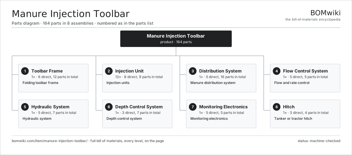
| # | Part | Qty | What it does |
|---|---|---|---|
| 1 | Toolbar Frame 6 parts | 1× | Folding toolbar frame |
| 2 | Injection Unit 8 parts | 12× | Injection units |
| 3 | Distribution System 5 parts | 1× | Manure distribution system |
| 4 | Flow Control System 5 parts | 1× | Flow and rate control |
| 5 | Hydraulic System 5 parts | 1× | Hydraulic system |
| 6 | Depth Control System 3 parts | 1× | Depth control system |
| 7 | Monitoring Electronics 5 parts | 1× | Monitoring electronics |
| 8 | Hitch 3 parts | 1× | Tanker or tractor hitch |
3D model
No 3D model yet. Have a CAD file of this? Add a 3D model — STL renders right on this page; STEP, FreeCAD, and OpenSCAD sources are welcome too (openly licensed, like all 3D models on BOMwiki).
Build & assembly graph
expand / collapse · shared sub-assemblies converge · links to related products · est. labourTap an assembly to expand/collapse · tap a part to open it · use “Open page” for any node · drag to pan, scroll to zoom.
Bill of materials for Manure Injection Toolbar
8 top-level lines · 48 rows shown · 164 parts total · indented to 3 levels| # | Item / sub-assembly | Part no. | Qty/assy | Ext. qty | Parts | Type |
|---|---|---|---|---|---|---|
| 1 | Toolbar Frame 6 parts | manure-injection-toolbar-frame | 1× | 1 | 12 | assembly |
| 1.1 | Center Frame | manure-injection-toolbar-main-frame | 1× | 1 | · | part |
| 1.2 | Folding Wing | manure-injection-toolbar-wing | 2× | 2 | · | part |
| 1.3 | Fold Pivot | manure-injection-toolbar-fold-pivot | 2× | 2 | · | part |
| 1.4 | Gauge Wheel | manure-injection-toolbar-gauge-wheel | 4× | 4 | · | part |
| 1.5 | Headland Wheel | manure-injection-toolbar-headland-wheel | 2× | 2 | · | part |
| 1.6 | Fastener Set | fastener-set | 1× | 1 | · | part |
| 2 | Injection Unit 8 parts | manure-injection-toolbar-injector-unit | 12× | 12 | 9 | assembly |
| 2.1 | Coulter Disc | manure-injection-toolbar-coulter-disc | 1× | 12 | · | part |
| 2.2 | Injector Tine | manure-injection-toolbar-injector-tine | 1× | 12 | · | part |
| 2.3 | Outlet Nozzle | manure-injection-toolbar-outlet | 1× | 12 | · | part |
| 2.4 | Closing Wheel | manure-injection-toolbar-closing-wheel | 1× | 12 | · | part |
| 2.5 | Parallel Arm | manure-injection-toolbar-parallel-arm | 1× | 12 | · | part |
| 2.6 | Down-Pressure Cylinder | manure-injection-toolbar-down-pressure | 1× | 12 | · | part |
| 2.7 | Coil Spring | coil-spring | 1× | 12 | · | part |
| 2.8 | Ball Bearing | ball-bearing | 2× | 24 | · | part |
| 3 | Distribution System 5 parts | manure-injection-toolbar-distribution | 1× | 1 | 16 | assembly |
| 3.1 | Macerator | manure-injection-toolbar-macerator | 1× | 1 | · | part |
| 3.2 | Flow Splitter | manure-injection-toolbar-splitter | 1× | 1 | · | part |
| 3.3 | Supply Hose | manure-injection-toolbar-supply-hose | 1× | 1 | · | part |
| 3.4 | Feed Hose | manure-injection-toolbar-feed-hose | 12× | 12 | · | part |
| 3.5 | Stone Trap | manure-injection-toolbar-stone-trap | 1× | 1 | · | part |
| 4 | Flow Control System 5 parts | manure-injection-toolbar-flow-control | 1× | 1 | 5 | assembly |
| 4.1 | Transfer Pump | manure-injection-toolbar-pump | 1× | 1 | · | part |
| 4.2 | Flow Meter | manure-injection-toolbar-flow-meter | 1× | 1 | · | part |
| 4.3 | Rate Valve | manure-injection-toolbar-rate-valve | 1× | 1 | · | part |
| 4.4 | Nutrient Sensor | manure-injection-toolbar-nutrient-sensor | 1× | 1 | · | part |
| 4.5 | Pressure Sensor | pressure-sensor | 1× | 1 | · | part |
| 5 | Hydraulic System 5 parts | manure-injection-toolbar-hydraulics | 1× | 1 | 7 | assembly |
| 5.1 | Fold Cylinder | manure-injection-toolbar-fold-cylinder | 2× | 2 | · | part |
| 5.2 | Lift Cylinder | manure-injection-toolbar-lift-cylinder | 2× | 2 | · | part |
| 5.3 | Valve Bank | manure-injection-toolbar-valve-bank | 1× | 1 | · | part |
| 5.4 | Accumulator | manure-injection-toolbar-accumulator | 1× | 1 | · | part |
| 5.5 | O-Ring Set | oring-set | 1× | 1 | · | part |
| 6 | Depth Control System 3 parts | manure-injection-toolbar-depth-control | 1× | 1 | 7 | assembly |
| 6.1 | Depth Wheel | manure-injection-toolbar-depth-wheel | 4× | 4 | · | part |
| 6.2 | Depth Sensor | manure-injection-toolbar-depth-sensor | 2× | 2 | · | part |
| 6.3 | Depth Adjuster | manure-injection-toolbar-depth-adjuster | 1× | 1 | · | part |
| 7 | Monitoring Electronics 5 parts | manure-injection-toolbar-electronics | 1× | 1 | 5 | assembly |
| 7.1 | Rate Controller | manure-injection-toolbar-controller | 1× | 1 | · | part |
| 7.2 | GNSS Receiver | manure-injection-toolbar-gps | 1× | 1 | · | part |
| 7.3 | In-Cab Terminal | manure-injection-toolbar-display | 1× | 1 | · | part |
| 7.4 | Microcontroller | mcu | 1× | 1 | · | part |
| 7.5 | Wire Bundle | wire-bundle | 1× | 1 | · | part |
| 8 | Hitch 3 parts | manure-injection-toolbar-hitch | 1× | 1 | 4 | assembly |
| 8.1 | Hitch Frame | manure-injection-toolbar-hitch-frame | 1× | 1 | · | part |
| 8.2 | Mounting Pin | manure-injection-toolbar-hitch-pin | 2× | 2 | · | part |
| 8.3 | Parking Stand | manure-injection-toolbar-jack | 1× | 1 | · | part |
Related products
same domain, ranked by shared parts Agricultural Spray Drone
721 parts · shares 5 with this page
Agricultural Spray Drone
721 parts · shares 5 with this page
 Anhydrous Ammonia Applicator
162 parts · shares 5 with this page
Anhydrous Ammonia Applicator
162 parts · shares 5 with this page
 Articulated Tractor
1,229 parts · shares 5 with this page
Articulated Tractor
1,229 parts · shares 5 with this page
 Boom Sprayer
356 parts · shares 5 with this page
Boom Sprayer
356 parts · shares 5 with this page
 Center-Pivot Irrigator
945 parts · shares 5 with this page
Center-Pivot Irrigator
945 parts · shares 5 with this page
 Feed Grinder Mixer
368 parts · shares 5 with this page
Feed Grinder Mixer
368 parts · shares 5 with this page
Sourcing: possible vendors
Prices, MOQ, and lead times are algorithmic estimates, not quotes, and not claims about these companies. Company mappings are curated by keyword; est. price band $5k–$800k. How estimates work| Vendor | HQ | Specialty | MOQ | Lead time |
|---|---|---|---|---|
| deere.com ↗ | Moline, US | Agriculture & turf | made to order | 14–24 wks |
| cnh.com ↗ | Basildon, GB | Agriculture (Case IH, New Holland) | made to order | 14–24 wks |
|
🇺🇸AGCO
agcocorp.com ↗
|
Duluth, US | Agriculture (Fendt, Massey Ferguson) | made to order | 14–24 wks |
|
🇩🇪Claas
claas.com ↗
|
Harsewinkel, DE | Harvesters & tractors | made to order | 14–24 wks |
|
🇯🇵Kubota
kubota.com ↗
|
Osaka, JP | Compact tractors & equipment | made to order | 14–24 wks |
897-word article