Air-Insulated Substation Bay
ProductOverview
An air-insulated substation bay is the outdoor switching and protection module that connects one transmission line, transformer, or feeder to the station busbars. Air-insulated means the working insulation between live parts and earth is the open atmosphere, so conductors and apparatus stand on tall insulators with generous clearances rather than being sealed inside gas enclosures. This makes the bay large but cheap, easy to inspect, and simple to extend, which is why most utility switchyards from 66 kV up to 400 kV use this construction.
A bay groups together a circuit breaker, one or more disconnectors, the instrument transformers that measure current and voltage, surge arresters, and the connecting busbars. All of it sits on a galvanized steel structure above a buried earthing grid, and a control and protection panel watches the bay and trips the breaker when a fault appears.
Steelwork and Layout
The support structure sets the geometry of the whole bay. Incoming line conductors land on a tall termination gantry, drop through insulator strings, and run along the bus to each apparatus, which stands on its own equipment stand. Clearances are dictated by the voltage class: a 400 kV bay needs roughly 3.5 m phase-to-earth in air, so the steelwork is correspondingly tall and widely spaced. Every member is hot-dip galvanized for a 30 to 40 year outdoor life, and each leg is fixed to its foundation with a cast-in anchor bolt set.
Busbar and Connections
The busbar system is the common node where bays meet. A double-bus arrangement runs two parallel main buses so a bay can be transferred from one bus to the other without interruption. The main bus is usually rigid aluminum tube carried on post insulators, while flexible stranded jumpers form the droppers down to each device. Bolted clamps make every joint, and on long spans a spacer damper absorbs wind-induced vibration that would otherwise fatigue the conductor.
Switching and Interruption
The SF6 circuit breaker does the heavy work of breaking fault current. Each phase has its own interrupter chamber where moving and fixed contacts part inside compressed sulfur hexafluoride. As the arcing contacts separate, the puffer cylinder compresses gas and blasts it through the PTFE nozzle across the arc, cooling and extinguishing it at a natural current zero. The stored-energy operating mechanism uses charged springs to drive the contacts in a few tens of milliseconds, and a charging motor re-cocks the closing spring afterward. Gas condition is watched continuously by an SF6 density monitor that alarms and finally locks out the breaker if gas leaks.
For isolation rather than interruption, each bay carries a disconnector group. The rotating blade swings open to leave a visible air gap that staff can see is safe, and an earthing blade grounds the dead conductor for maintenance. A motorized drive unit operates the blade, while an interlock makes it impossible to open the isolator while it still carries load.
Measurement and Surge Protection
Protection and metering need scaled-down copies of the line current and voltage, which is the job of the instrument transformer set. A current transformer wound on a toroidal core delivers a 1 A or 5 A secondary proportional to line current, and a voltage transformer taps a capacitor divider to produce a 110 V secondary. Both reference everything to the relays in the control panel.
Lightning strokes and switching transients can briefly drive line voltage far above normal, so each bay has a surge arrester set. The metal-oxide arrester is a stacked column of zinc-oxide blocks whose resistance collapses above a threshold voltage, diverting surge energy to the earth grid and clamping the voltage that reaches the breaker and transformer insulation. A surge counter logs each operation.
Earthing and Control
Safety rests on the earthing grid, a buried mesh of bare copper conductor tied to driven earth rods with exothermic welds. The grid holds step and touch voltages within safe limits during a fault and bonds every piece of steelwork through an earth riser.
The control and protection panel is the brain. Two numerical relays, a main and a backup, sample the instrument-transformer secondaries through an analog input board and run distance and overcurrent algorithms that trip the breaker in under 100 ms for an in-zone fault. An RTU gateway reports bay status to the control center over IEC 61850, and a DC battery system guarantees tripping power even with the station AC supply lost.
Variants and Use
Air-insulated bays scale across the voltage range by changing clearances, insulator string length, and steel height. Where land is scarce or the climate corrosive, utilities choose gas-insulated switchgear instead, trading a much smaller footprint for higher cost and sealed maintenance. The air-insulated bay remains the default for greenfield transmission switchyards because it is inexpensive per bay, simple to fault-find by eye, and straightforward to expand one bay at a time as the network grows.
Air-Insulated Substation Bay parts and their functions
9 top-level parts · 1,329 parts in total · full bill of materials below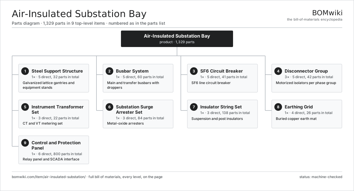
| # | Part | Qty | What it does |
|---|---|---|---|
| 1 | Steel Support Structure 5 parts | 1× | Galvanized lattice gantries and equipment stands |
| 2 | Busbar System 5 parts | 1× | Main and transfer busbars with droppers |
| 3 | SF6 Circuit Breaker 5 parts | 1× | SF6 line circuit breaker |
| 4 | Disconnector Group 5 parts | 3× | Motorized isolators per phase group |
| 5 | Instrument Transformer Set 3 parts | 1× | CT and VT metering set |
| 6 | Substation Surge Arrester Set 3 parts | 1× | Metal-oxide arresters |
| 7 | Insulator String Set 3 parts | 1× | Suspension and post insulators |
| 8 | Earthing Grid 4 parts | 1× | Buried copper earth mat |
| 9 | Control and Protection Panel 6 parts | 1× | Relay panel and SCADA interface |
3D model
No 3D model yet. Have a CAD file of this? Add a 3D model. STL renders right on this page; STEP, FreeCAD, and OpenSCAD sources are welcome too (openly licensed, like all 3D models on BOMwiki).
Build & assembly graph
expand / collapse · shared sub-assemblies converge · links to related products · est. labourTap an assembly to expand/collapse · tap a part to open it · use “Open page” for any node · drag to pan, scroll to zoom.
Bill of materials for Air-Insulated Substation Bay
9 top-level lines · 88 rows shown · 1,329 parts total · indented to 3 levels| # | Item / sub-assembly | Part no. | Qty/assy | Ext. qty | Parts | Type |
|---|---|---|---|---|---|---|
| 1 | Steel Support Structure 5 parts | ais-steel-structure | 1× | 1 | 32 | assembly |
| 1.1 | Termination Gantry | ais-gantry-tower | 2× | 2 | · | part |
| 1.2 | Equipment Support Stand | ais-equipment-stand | 6× | 6 | · | part |
| 1.3 | Structural Channel Beam | ais-beam-channel | 12× | 12 | · | part |
| 1.4 | Foundation Anchor Bolt Set | ais-anchor-bolt-set | 8× | 8 | · | part |
| 1.5 | Fastener Set | fastener-set | 4× | 4 | · | part |
| 2 | Busbar System 5 parts | ais-busbar-system | 1× | 1 | 60 | assembly |
| 2.1 | Tubular Busbar | ais-tubular-busbar | 6× | 6 | · | part |
| 2.2 | Stranded Jumper Conductor | ais-stranded-jumper | 12× | 12 | · | part |
| 2.3 | Busbar Clamp | ais-busbar-clamp | 24× | 24 | · | part |
| 2.4 | Spacer Damper | ais-spacer-damper | 6× | 6 | · | part |
| 2.5 | Post Insulator | ais-post-insulator | 12× | 12 | · | part |
| 3 | SF6 Circuit Breaker 5 parts | ais-circuit-breaker | 1× | 1 | 41 | assembly |
| 3.1 | Interrupter Chamber 5 parts | ais-interrupter-chamber | 3× | 3 | 8 | assembly |
| 3.1.1 | Arcing Contact | ais-arcing-contact | 2× | 6 | · | part |
| 3.1.2 | Main Contact | ais-main-contact | 2× | 6 | · | part |
| 3.1.3 | PTFE Arcing Nozzle | ais-nozzle-ptfe | 1× | 3 | · | part |
| 3.1.4 | Puffer Cylinder | ais-puffer-cylinder | 1× | 3 | · | part |
| 3.1.5 | O-Ring Set | oring-set | 2× | 6 | · | part |
| 3.2 | Operating Mechanism 6 parts | ais-operating-mechanism | 1× | 1 | 8 | assembly |
| 3.2.1 | Coil Spring | coil-spring | 2× | 2 | · | part |
| 3.2.2 | Spring Charging Motor | ais-charging-motor | 1× | 1 | · | part |
| 3.2.3 | Trip Coil | ais-trip-coil | 2× | 2 | · | part |
| 3.2.4 | Closing Coil | ais-close-coil | 1× | 1 | · | part |
| 3.2.5 | Auxiliary Switch | ais-aux-switch | 1× | 1 | · | part |
| 3.2.6 | Helical Gear Pair | gear-pair | 1× | 1 | · | part |
| 3.3 | SF6 Density Monitor | ais-sf6-density-monitor | 3× | 3 | · | part |
| 3.4 | Support Insulator Column | ais-support-insulator-column | 3× | 3 | · | part |
| 3.5 | Grading Capacitor | ais-grading-capacitor | 3× | 3 | · | part |
| 4 | Disconnector Group 5 parts | ais-disconnector-bank | 3× | 3 | 42 | assembly |
| 4.1 | Rotating Isolator Blade | ais-rotating-blade | 3× | 9 | · | part |
| 4.2 | Earthing Blade | ais-earth-blade | 3× | 9 | · | part |
| 4.3 | Motorized Drive Unit 4 parts | ais-disconnector-motor-drive | 1× | 3 | 29 | assembly |
| 4.3.1 | Servo Motor 4 parts + deeper › | servo-motor | 1× | 3 | 24 | assembly |
| 4.3.2 | Helical Gear Pair | gear-pair | 1× | 3 | · | part |
| 4.3.3 | Auxiliary Switch | ais-aux-switch | 2× | 6 | · | part |
| 4.3.4 | Limit Switch | limit-switch | 2× | 6 | · | part |
| 4.4 | Post Insulator | ais-post-insulator | 6× | 18 | · | part |
| 4.5 | Interlock Unit | ais-interlock-unit | 1× | 3 | · | part |
| 5 | Instrument Transformer Set 3 parts | ais-instrument-transformers | 1× | 1 | 22 | assembly |
| 5.1 | Current Transformer 4 parts | ais-current-transformer | 3× | 3 | 4 | assembly |
| 5.1.1 | CT Toroidal Core | ais-ct-core | 1× | 3 | · | part |
| 5.1.2 | Copper Winding | copper-winding | 1× | 3 | · | part |
| 5.1.3 | Porcelain Housing | ais-porcelain-housing | 1× | 3 | · | part |
| 5.1.4 | Oil Seal | oil-seal | 1× | 3 | · | part |
| 5.2 | Voltage Transformer 3 parts | ais-voltage-transformer | 3× | 3 | 3 | assembly |
| 5.2.1 | Capacitor Voltage Divider Stack | ais-cap-stack | 1× | 3 | · | part |
| 5.2.2 | Copper Winding | copper-winding | 1× | 3 | · | part |
| 5.2.3 | Porcelain Housing | ais-porcelain-housing | 1× | 3 | · | part |
| 5.3 | Secondary Junction Box | ais-secondary-junction-box | 1× | 1 | · | part |
| 6 | Substation Surge Arrester Set 3 parts | ais-surge-arrester-set | 1× | 1 | 84 | assembly |
| 6.1 | Metal-Oxide Arrester 3 parts | ais-mov-arrester | 3× | 3 | 26 | assembly |
| 6.1.1 | Zinc-Oxide Varistor Block | ais-zno-block | 24× | 72 | · | part |
| 6.1.2 | Silicone Polymer Housing | ais-polymer-housing | 1× | 3 | · | part |
| 6.1.3 | Corona Grading Ring | ais-grading-ring | 1× | 3 | · | part |
| 6.2 | Surge Counter | ais-surge-counter | 3× | 3 | · | part |
| 6.3 | Post Insulator | ais-post-insulator | 3× | 3 | · | part |
| 7 | Insulator String Set 3 parts | ais-insulator-string-set | 1× | 1 | 138 | assembly |
| 7.1 | Suspension Insulator String 2 parts | ais-suspension-string | 6× | 6 | 20 | assembly |
| 7.1.1 | Toughened Glass Disc | ais-glass-disc | 18× | 108 | · | part |
| 7.1.2 | Ball-and-Socket Link | ais-ball-socket-link | 2× | 12 | · | part |
| 7.2 | Corona Ring | ais-corona-ring | 6× | 6 | · | part |
| 7.3 | Conductor Clamp | ais-conductor-clamp | 12× | 12 | · | part |
| 8 | Earthing Grid 4 parts | ais-earthing-grid | 1× | 1 | 26 | assembly |
| 8.1 | Bare Copper Earth Conductor | ais-earth-conductor | 1× | 1 | · | part |
| 8.2 | Earth Rod | ais-earth-rod | 16× | 16 | · | part |
| 8.3 | Exothermic Joint Kit | ais-exothermic-joint-kit | 1× | 1 | · | part |
| 8.4 | Earth Riser | ais-earth-riser | 8× | 8 | · | part |
| 9 | Control and Protection Panel 6 parts | ais-control-protection | 1× | 1 | 800 | assembly |
| 9.1 | Numerical Protection Relay 6 parts | ais-protection-relay | 2× | 2 | 338 | assembly |
| 9.1.1 | Bare PCB | pcb-bare | 2× | 4 | · | part |
| 9.1.2 | Microcontroller | mcu | 2× | 4 | · | part |
| 9.1.3 | Analog Input Board 3 parts + deeper › | ais-analog-input-board | 1× | 2 | 125 | assembly |
| 9.1.4 | LCD Panel | lcd-panel | 1× | 2 | · | part |
| 9.1.5 | Relay | relay | 8× | 16 | · | part |
| 9.1.6 | SMD Passive (R/C/L) | smd-passives | 200× | 400 | · | part |
| 9.2 | Control Cubicle | ais-control-cubicle | 1× | 1 | · | part |
| 9.3 | SCADA RTU Gateway 4 parts | ais-rtu-gateway | 1× | 1 | 104 | assembly |
| 9.3.1 | Bare PCB | pcb-bare | 1× | 1 | · | part |
| 9.3.2 | Microcontroller | mcu | 1× | 1 | · | part |
| 9.3.3 | Connector | connector | 12× | 12 | · | part |
| 9.3.4 | SMD Passive (R/C/L) | smd-passives | 90× | 90 | · | part |
| 9.4 | DC Battery System 3 parts | ais-dc-battery-system | 1× | 1 | 14 | assembly |
| 9.4.1 | Station Battery Bank | ais-battery-bank | 1× | 1 | · | part |
| 9.4.2 | Battery Charger 4 parts + deeper › | ais-battery-charger | 1× | 1 | 12 | assembly |
| 9.4.3 | DC Distribution Board | ais-dc-distribution-board | 1× | 1 | · | part |
| 9.5 | Wire Bundle | wire-bundle | 4× | 4 | · | part |
| 9.6 | Mimic Control Panel | ais-mimic-panel | 1× | 1 | · | part |
Related products
same domain, ranked by shared parts HVDC Converter Station
18,173 parts · shares 46 with this page
HVDC Converter Station
18,173 parts · shares 46 with this page
 Home Battery Storage
292 parts · shares 6 with this page
Bottom Ash Handling System
1,782 parts · shares 19 with this page
Home Battery Storage
292 parts · shares 6 with this page
Bottom Ash Handling System
1,782 parts · shares 19 with this page
 Combined Heat and Power Unit
522 parts · shares 19 with this page
Combined Heat and Power Unit
522 parts · shares 19 with this page
 Coal Pulverizer Mill
313 parts · shares 18 with this page
Coal Pulverizer Mill
313 parts · shares 18 with this page
 Large Power Transformer
1,844 parts · shares 17 with this page
Large Power Transformer
1,844 parts · shares 17 with this page
Sourcing: possible vendors
Browse the supplier directory → Prices, MOQ, and lead times are algorithmic estimates, not quotes, and not claims about these companies. Company mappings are curated by keyword; est. price band $5k–$50M. How estimates work| Vendor | HQ | Specialty | MOQ | Lead time |
|---|---|---|---|---|
| gevernova.com ↗ | Cambridge, US | Power generation | made to order | 20–40 wks |
| siemens-energy.com ↗ | Munich, DE | Power & grid | made to order | 20–40 wks |
| hitachienergy.com ↗ | Zurich, CH | Grid & transformers | made to order | 20–40 wks |
|
🇨🇭ABB
abb.com ↗
|
Zurich, CH | Electrification & automation | made to order | 20–40 wks |
| se.com ↗ | Rueil-Malmaison, FR | Electrical & automation | made to order | 20–40 wks |
994-word article