Geothermal Steam Separator
ProductOverview
A geothermal steam separator takes the two-phase mixture that comes up a production well, a churn of saturated steam and hot saline water known as brine, and splits it into a dry steam stream and a liquid brine stream. Most geothermal power plants run on liquid-dominated reservoirs, so the fluid arriving at surface is mostly water by mass with a steam fraction of roughly 10 to 30 percent depending on reservoir enthalpy and wellhead pressure. The turbine can only accept dry steam, because liquid droplets erode the blades and carry dissolved silica and chloride salts that foul and corrode the machine. The separator stands between the wellhead and the steam gathering line and decides how clean that steam will be.
The design used across almost every geothermal field is the Webre vertical cyclone, a centrifugal separator named after the configuration that the Geothermal Energy New Zealand engineers standardised at Wairakei in the 1950s. The two-phase fluid enters tangentially near the top, spins down the wall of a Pressure Vessel Shell, and the density difference between water and steam does the work. Brine is thrown outward to the wall and drains to the bottom, while steam moves to the low-velocity core and rises out of the top. There are no moving parts in the separation itself, which is why these vessels run for decades with only periodic internal inspection.
How it works
Separation is driven by centrifugal force. The Tangential Inlet Nozzle admits the mixture tangentially at 25 to 45 m/s, and the Inlet Volute Scroll turns that jet smoothly onto the shell wall so it forms a downward spiral. In the spinning flow each brine droplet feels a centrifugal acceleration many times gravity, far larger than the drag from the steam, so droplets migrate to the wall and coalesce into a film. That film runs down the wall, past the Baffle Cone, and collects as a brine pool in the bottom head.
Steam, being roughly twenty to forty times less dense than the brine at separation pressure, is left in the central core. The Vortex Finder (Dip Pipe) is a dip pipe hanging below the steam outlet that draws steam from this core while rejecting droplets that would otherwise be re-entrained near the top. Steam then passes the Anti-Swirl Vane set, which removes residual rotation and recovers some pressure, and leaves through the Steam Outlet Riser. For fields with strict turbine specifications a Wire-Mesh Demister Pad of knitted stainless mesh is fitted before the outlet, coalescing the last fine droplets and lifting steam dryness above 99.95 percent.
Brine handling and level control
The brine pool at the bottom is not static. Brine drains continuously through the Brine Outlet & Vortex Breaker to either a second-stage flash vessel or a reinjection line that returns it to the reservoir. The pool depth has to stay inside a band: too high and brine is carried up into the steam, too low and steam blows through into the brine line, a fault called carry-under that wastes energy and can cavitate downstream pumps.
Level is held by the Brine Level Control. A Brine Level Transmitter reads the brine interface against an external Water-Level Standpipe, and the controller modulates the Brine Control Valve on the brine drain. A Vortex Breaker Plate sits over the drain to stop a gas-cored vortex forming as brine accelerates into the nozzle, which would otherwise pull steam down with the liquid. Because the control valve sees high-velocity scaling brine it uses erosion-resistant trim and is treated as a wear item.
Materials, scaling and corrosion
Geothermal brine is aggressive. It is hot, saline, often acidic, and saturated in silica that drops out of solution as the fluid cools and flashes. The shell is normally carbon steel to ASME SA-516 Gr 70 with a corrosion allowance of around 3 mm, and a Corrosion Allowance Liner adds extra sacrificial thickness at the high-erosion swirl zones. The Inlet Wear Plate takes the direct impingement of the incoming jet and is a replaceable hardfaced part. Internals that stay wet, the Cyclone Barrel, vortex finder and demister, are stainless steel 316L to resist chloride attack.
Silica scale is the dominant maintenance problem. As brine flashes inside the vessel the silica concentrates and deposits on every wetted surface, narrowing the brine drain and blinding the demister. Operators schedule shutdowns to enter through the Inspection Manway and mechanically descale the internals, and a Brine Strainer catches the scale fragments that spall off so they do not block the control valve.
Pressure protection
The separator is a coded pressure vessel and is protected against overpressure from well surges and downstream valve closures. The Pressure Relief System system carries a spring Safety Relief Valve sized for full steam relief at the vessel set pressure, backed by a Rupture Disc that gives fast secondary relief in a rapid transient. The relief discharge passes through a Vent Silencer because an uncontrolled steam blow is extremely loud. Design follows ASME VIII Division 1, with the relief set point below the maximum allowable working pressure and the well unable to exceed the vessel rating under shut-in conditions.
Instrumentation and integration
The vessel reports to the field control system through its Instrumentation. Pressure transmitters on the vessel and steam line, RTD thermowells confirming saturation temperature, and separate steam and brine flow meters let operators track the mass balance and infer steam quality from the energy split. Steam dryness is the figure the plant cares about most, because a fraction of a percent of carried-over moisture across a 100 MW station is a large annual loss in turbine output and blade life.
In the wider plant the separator sits at the head of the steam gathering network. In a single-flash station its steam goes straight to the turbine and its brine to reinjection. In a double-flash station the brine drops to a lower-pressure flash vessel that recovers a second steam stream, raising plant output by 15 to 25 percent. The Support, Access & Insulation structure carries the vessel several metres off the ground so brine drains by gravity to the flash or reinjection line, and the Thermal Insulation keeps the wall near saturation temperature so the separation stays clean and the steel stays above the dew point.
Geothermal Steam Separator parts and their functions
9 top-level parts · 77 parts in total · full bill of materials below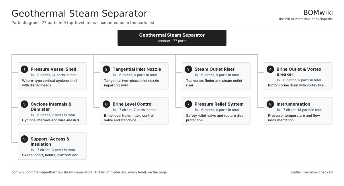
| # | Part | Qty | What it does |
|---|---|---|---|
| 1 | Pressure Vessel Shell 9 parts | 1× | Webre-type vertical cyclone shell with dished heads |
| 2 | Tangential Inlet Nozzle 6 parts | 1× | Tangential two-phase inlet nozzle imparting swirl |
| 3 | Steam Outlet Riser 6 parts | 1× | Top vortex finder and steam outlet riser |
| 4 | Brine Outlet & Vortex Breaker 6 parts | 1× | Bottom brine drain with vortex breaker |
| 5 | Cyclone Internals & Demister 6 parts | 1× | Cyclone internals and wire-mesh demister stage |
| 6 | Brine Level Control 7 parts | 1× | Brine level transmitter, control valve and standpipe |
| 7 | Pressure Relief System 6 parts | 1× | Safety relief valve and rupture disc protection |
| 8 | Instrumentation 7 parts | 1× | Pressure, temperature and flow instrumentation |
| 9 | Support, Access & Insulation 7 parts | 1× | Skirt support, ladder, platform and insulation |
3D model
No 3D model yet. Have a CAD file of this? Add a 3D model. STL renders right on this page; STEP, FreeCAD, and OpenSCAD sources are welcome too (openly licensed, like all 3D models on BOMwiki).
Build & assembly graph
expand / collapse · shared sub-assemblies converge · links to related products · est. labourTap an assembly to expand/collapse · tap a part to open it · use “Open page” for any node · drag to pan, scroll to zoom.
Bill of materials for Geothermal Steam Separator
9 top-level lines · 69 rows shown · 77 parts total · indented to 3 levels| # | Item / sub-assembly | Part no. | Qty/assy | Ext. qty | Parts | Type |
|---|---|---|---|---|---|---|
| 1 | Pressure Vessel Shell 9 parts | geothermal-steam-separator-pressure-vessel | 1× | 1 | 14 | assembly |
| 1.1 | Shell Course | geothermal-steam-separator-shell-course | 2× | 2 | · | part |
| 1.2 | Top Ellipsoidal Head | geothermal-steam-separator-top-head | 1× | 1 | · | part |
| 1.3 | Bottom Head | geothermal-steam-separator-bottom-head | 1× | 1 | · | part |
| 1.4 | Corrosion Allowance Liner | geothermal-steam-separator-corrosion-allowance-liner | 1× | 1 | · | part |
| 1.5 | ASME Data Nameplate | geothermal-steam-separator-nameplate | 1× | 1 | · | part |
| 1.6 | Inspection Manway | geothermal-steam-separator-manway | 1× | 1 | · | part |
| 1.7 | Drain / Sample Boss | geothermal-steam-separator-drain-boss | 2× | 2 | · | part |
| 1.8 | Fastener Set | fastener-set | 4× | 4 | · | part |
| 1.9 | O-Ring Set | oring-set | 1× | 1 | · | part |
| 2 | Tangential Inlet Nozzle 6 parts | geothermal-steam-separator-inlet | 1× | 1 | 6 | assembly |
| 2.1 | Inlet Nozzle Pipe | geothermal-steam-separator-inlet-nozzle | 1× | 1 | · | part |
| 2.2 | Inlet Weld-Neck Flange | geothermal-steam-separator-inlet-flange | 1× | 1 | · | part |
| 2.3 | Inlet Wear Plate | geothermal-steam-separator-inlet-wear-plate | 1× | 1 | · | part |
| 2.4 | Inlet Volute Scroll | geothermal-steam-separator-inlet-scroll | 1× | 1 | · | part |
| 2.5 | O-Ring Set | oring-set | 1× | 1 | · | part |
| 2.6 | Fastener Set | fastener-set | 1× | 1 | · | part |
| 3 | Steam Outlet Riser 6 parts | geothermal-steam-separator-steam-outlet | 1× | 1 | 9 | assembly |
| 3.1 | Vortex Finder (Dip Pipe) | geothermal-steam-separator-vortex-finder | 1× | 1 | · | part |
| 3.2 | Steam Outlet Nozzle | geothermal-steam-separator-steam-nozzle | 1× | 1 | · | part |
| 3.3 | Steam Outlet Flange | geothermal-steam-separator-steam-flange | 1× | 1 | · | part |
| 3.4 | Anti-Swirl Vane | geothermal-steam-separator-anti-swirl-vane | 4× | 4 | · | part |
| 3.5 | O-Ring Set | oring-set | 1× | 1 | · | part |
| 3.6 | Fastener Set | fastener-set | 1× | 1 | · | part |
| 4 | Brine Outlet & Vortex Breaker 6 parts | geothermal-steam-separator-brine-outlet | 1× | 1 | 6 | assembly |
| 4.1 | Brine Outlet Nozzle | geothermal-steam-separator-brine-nozzle | 1× | 1 | · | part |
| 4.2 | Vortex Breaker Plate | geothermal-steam-separator-vortex-breaker | 1× | 1 | · | part |
| 4.3 | Brine Outlet Flange | geothermal-steam-separator-brine-flange | 1× | 1 | · | part |
| 4.4 | Brine Strainer | geothermal-steam-separator-brine-strainer | 1× | 1 | · | part |
| 4.5 | O-Ring Set | oring-set | 1× | 1 | · | part |
| 4.6 | Fastener Set | fastener-set | 1× | 1 | · | part |
| 5 | Cyclone Internals & Demister 6 parts | geothermal-steam-separator-internals | 1× | 1 | 7 | assembly |
| 5.1 | Cyclone Barrel | geothermal-steam-separator-cyclone-barrel | 1× | 1 | · | part |
| 5.2 | Wire-Mesh Demister Pad | geothermal-steam-separator-demister-pad | 1× | 1 | · | part |
| 5.3 | Demister Support Grid | geothermal-steam-separator-demister-grid | 2× | 2 | · | part |
| 5.4 | Baffle Cone | geothermal-steam-separator-baffle-cone | 1× | 1 | · | part |
| 5.5 | Drain Skirt | geothermal-steam-separator-drain-skirt | 1× | 1 | · | part |
| 5.6 | Fastener Set | fastener-set | 1× | 1 | · | part |
| 6 | Brine Level Control 7 parts | geothermal-steam-separator-level-control | 1× | 1 | 7 | assembly |
| 6.1 | Brine Level Transmitter | geothermal-steam-separator-level-transmitter | 1× | 1 | · | part |
| 6.2 | Water-Level Standpipe | geothermal-steam-separator-standpipe | 1× | 1 | · | part |
| 6.3 | Magnetic Level Gauge | geothermal-steam-separator-level-gauge | 1× | 1 | · | part |
| 6.4 | Brine Control Valve | geothermal-steam-separator-control-valve | 1× | 1 | · | part |
| 6.5 | Valve Actuator | geothermal-steam-separator-valve-actuator | 1× | 1 | · | part |
| 6.6 | Pressure Sensor | pressure-sensor | 1× | 1 | · | part |
| 6.7 | Fastener Set | fastener-set | 1× | 1 | · | part |
| 7 | Pressure Relief System 6 parts | geothermal-steam-separator-relief | 1× | 1 | 6 | assembly |
| 7.1 | Safety Relief Valve | geothermal-steam-separator-relief-valve | 1× | 1 | · | part |
| 7.2 | Rupture Disc | geothermal-steam-separator-rupture-disc | 1× | 1 | · | part |
| 7.3 | Relief Nozzle | geothermal-steam-separator-relief-nozzle | 1× | 1 | · | part |
| 7.4 | Vent Silencer | geothermal-steam-separator-vent-silencer | 1× | 1 | · | part |
| 7.5 | O-Ring Set | oring-set | 1× | 1 | · | part |
| 7.6 | Fastener Set | fastener-set | 1× | 1 | · | part |
| 8 | Instrumentation 7 parts | geothermal-steam-separator-instrumentation | 1× | 1 | 14 | assembly |
| 8.1 | Pressure Sensor | pressure-sensor | 2× | 2 | · | part |
| 8.2 | RTD Thermowell | geothermal-steam-separator-temperature-element | 2× | 2 | · | part |
| 8.3 | Steam Flow Meter | geothermal-steam-separator-steam-flow-meter | 1× | 1 | · | part |
| 8.4 | Brine Flow Meter | geothermal-steam-separator-brine-flow-meter | 1× | 1 | · | part |
| 8.5 | Instrument Junction Box | geothermal-steam-separator-junction-box | 1× | 1 | · | part |
| 8.6 | Wire Bundle | wire-bundle | 1× | 1 | · | part |
| 8.7 | Connector | connector | 6× | 6 | · | part |
| 9 | Support, Access & Insulation 7 parts | geothermal-steam-separator-support | 1× | 1 | 8 | assembly |
| 9.1 | Support Skirt | geothermal-steam-separator-skirt | 1× | 1 | · | part |
| 9.2 | Anchor Bolt Set | geothermal-steam-separator-anchor-bolts | 1× | 1 | · | part |
| 9.3 | Access Platform | geothermal-steam-separator-platform | 1× | 1 | · | part |
| 9.4 | Caged Ladder | geothermal-steam-separator-ladder | 1× | 1 | · | part |
| 9.5 | Thermal Insulation | geothermal-steam-separator-insulation | 1× | 1 | · | part |
| 9.6 | Weather Cladding | geothermal-steam-separator-cladding | 1× | 1 | · | part |
| 9.7 | Lifting Lug | geothermal-steam-separator-lifting-lug | 2× | 2 | · | part |
Related products
same domain, ranked by shared parts Autotransformer
7,784 parts · shares 3 with this page
Bottom Ash Handling System
1,782 parts · shares 3 with this page
Autotransformer
7,784 parts · shares 3 with this page
Bottom Ash Handling System
1,782 parts · shares 3 with this page
 Combined Heat and Power Unit
522 parts · shares 3 with this page
Containerized Diesel Genset
655 parts · shares 3 with this page
Combined Heat and Power Unit
522 parts · shares 3 with this page
Containerized Diesel Genset
655 parts · shares 3 with this page
 Distribution Ring Main Unit
443 parts · shares 3 with this page
Distribution Ring Main Unit
443 parts · shares 3 with this page
 Electric Arc Furnace Transformer
522 parts · shares 3 with this page
Electric Arc Furnace Transformer
522 parts · shares 3 with this page
Sourcing: possible vendors
Browse the supplier directory → Prices, MOQ, and lead times are algorithmic estimates, not quotes, and not claims about these companies. Company mappings are curated by keyword; est. price band $5k–$50M. How estimates work| Vendor | HQ | Specialty | MOQ | Lead time |
|---|---|---|---|---|
| gevernova.com ↗ | Cambridge, US | Power generation | made to order | 20–40 wks |
| siemens-energy.com ↗ | Munich, DE | Power & grid | made to order | 20–40 wks |
| hitachienergy.com ↗ | Zurich, CH | Grid & transformers | made to order | 20–40 wks |
|
🇨🇭ABB
abb.com ↗
|
Zurich, CH | Electrification & automation | made to order | 20–40 wks |
| se.com ↗ | Rueil-Malmaison, FR | Electrical & automation | made to order | 20–40 wks |
1,115-word article