Cooling Tower Cell
ProductOverview
A cooling tower cell rejects waste heat from a circulating water loop to the atmosphere by evaporating a small fraction of that water. Hot water returning from condensers, process heat exchangers, or chillers is sprayed over a large surface of fill media while a fan draws ambient air through it. Part of the water evaporates, and because evaporation carries away the latent heat of vaporization, the bulk water that drains into the basin leaves several degrees cooler than it entered. A multi-cell tower is built by placing identical cells side by side and sharing a common hot water supply and cold water basin; each cell is a self-contained module with its own fan, fill, and water distribution.
The cell described here is an induced-draft design, meaning the fan sits at the top of the cell and pulls air upward through the fill, discharging warm saturated air through the fan cylinder. This arrangement gives even air distribution through the fill and discharges the plume high enough to limit recirculation back into the air inlets. The performance of a cell is set by the wet-bulb temperature of the incoming air, the water flow rate, and the heat-transfer area of the fill, summarized by the approach (how close the cold water comes to the ambient wet-bulb) and the range (how far the water cools across the cell).
Air and water path
Hot water enters through the Hot Water Distribution system, where a header feeds several laterals fitted with non-clog gravity nozzles. The nozzles break the water into a uniform rain across the top of the Fill Pack. The fill is a stack of thermoformed PVC sheets whose corrugations spread the water into thin films and break it into droplets, exposing the maximum surface area to the air for the longest possible contact time. As the water trickles down through the fill, the upward air stream evaporates a thin layer from each surface and carries the resulting vapor and sensible heat upward.
Air enters through the Air Inlet Louvers field at the lower sides of the cell. The inclined louver blades admit air, block direct sunlight that would otherwise grow algae in the fill, and contain splash water inside the casing. After passing through the fill counter to the falling water, the now warm and nearly saturated air rises through the Drift Eliminator Bank bank. These multi-pass PVC blades force the air to change direction several times so that entrained water droplets impinge on the blade walls and drain back, holding drift loss below 0.005 percent of the circulating flow.
Fan and drive
The Fan and Drive Stack is the only powered subsystem. A large-diameter axial fan with tapered FRP blades mounts on a cast hub and turns slowly, typically 100 to 350 rpm, to move very high air volumes at low pressure. Because the motor cannot run at fan speed, a right-angle Right-Angle Gearbox with a spiral-bevel gear set reduces the motor speed and turns the drive from horizontal to vertical. A floating composite Drive Shaft links the Fan Motor on the dry side of the deck to the gearbox, isolating the motor from fan thrust and accommodating slight misalignment. A velocity recovery fan cylinder around the blade tips reduces tip leakage and converts some exit velocity back into static pressure, improving fan efficiency by several percent. A mechanical vibration switch trips the motor if a blade cracks or ice forms unevenly.
Structure and basin
The whole cell hangs on the Cell Structure and Casing, a frame of vertical columns and horizontal girts that carries the fill, the water distribution, the fan deck, and the casing panels. Pultruded fiberglass is common in corrosive or chemically treated water because it never rusts; hot-dip galvanized steel is used where first cost matters more than service life. Cooled water collects in the Cold Water Basin below the fill. The basin includes an anti-vortex suction screen at the pump outlet, a float-operated makeup valve to replace water lost to evaporation and blowdown, and an overflow standpipe that fixes the operating level. A side-stream strainer keeps sediment and biological growth from reaching the spray nozzles.
Materials
Film fill, drift eliminators, and louvers are all PVC because it resists the warm, oxygen-rich, sometimes chemically dosed water and is easy to thermoform into precise corrugations. The frame is FRP or galvanized steel, hardware is stainless throughout the wet section, and the gearbox housing is cast iron with synthetic gear oil rated for continuous duty in a humid environment. The basin is concrete on large field-erected towers and steel or lined FRP on packaged units.
Controls and operation
The Controls and Instrumentation panel manages capacity by varying fan speed through a variable frequency drive, staging cells in a multi-cell tower, and protecting against freezing. RTD sensors on the hot inlet and cold basin water let the controller hold a leaving water setpoint by trimming fan speed, which saves large amounts of fan energy at part load and in cool weather. A basin level transmitter drives the makeup valve and protects the pumps against running dry. Water treatment, dosing biocide and scale inhibitor and controlling cycles of concentration through blowdown, runs alongside the temperature controls because the same warm aerated water that cools well also encourages scale, corrosion, and Legionella growth if left untreated.
Use and maintenance
Cooling tower cells serve power plant condensers, large building chiller plants, refineries, and any process that must continuously dump heat to the environment. Routine maintenance covers gearbox oil changes, fan balance checks, fill and nozzle cleaning, basin sweeping, and drift eliminator inspection. The dominant operating costs are fan energy, makeup water, and the chemicals needed to keep the wetted surfaces clean, so efficient fills, well-aimed nozzles, and tight fan control directly lower both the water and energy bills of the whole cooling system.
Cooling Tower Cell parts and their functions
8 top-level parts · 219 parts in total · full bill of materials below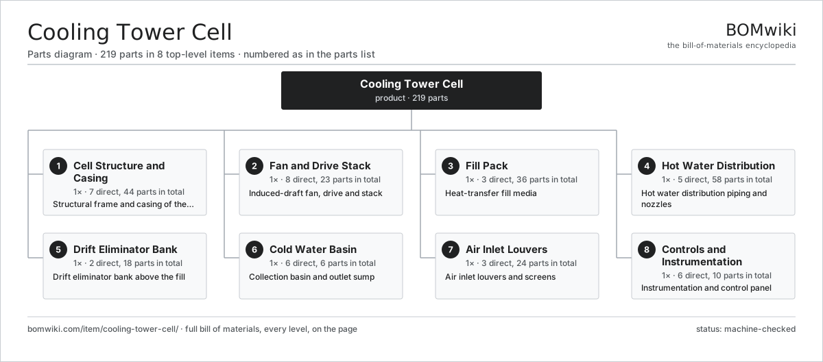
| # | Part | Qty | What it does |
|---|---|---|---|
| 1 | Cell Structure and Casing 7 parts | 1× | Structural frame and casing of the cell |
| 2 | Fan and Drive Stack 8 parts | 1× | Induced-draft fan, drive and stack |
| 3 | Fill Pack 3 parts | 1× | Heat-transfer fill media |
| 4 | Hot Water Distribution 5 parts | 1× | Hot water distribution piping and nozzles |
| 5 | Drift Eliminator Bank 2 parts | 1× | Drift eliminator bank above the fill |
| 6 | Cold Water Basin 6 parts | 1× | Collection basin and outlet sump |
| 7 | Air Inlet Louvers 3 parts | 1× | Air inlet louvers and screens |
| 8 | Controls and Instrumentation 6 parts | 1× | Instrumentation and control panel |
3D model
No 3D model yet. Have a CAD file of this? Add a 3D model. STL renders right on this page; STEP, FreeCAD, and OpenSCAD sources are welcome too (openly licensed, like all 3D models on BOMwiki).
Build & assembly graph
expand / collapse · shared sub-assemblies converge · links to related products · est. labourTap an assembly to expand/collapse · tap a part to open it · use “Open page” for any node · drag to pan, scroll to zoom.
Bill of materials for Cooling Tower Cell
8 top-level lines · 52 rows shown · 219 parts total · indented to 3 levels| # | Item / sub-assembly | Part no. | Qty/assy | Ext. qty | Parts | Type |
|---|---|---|---|---|---|---|
| 1 | Cell Structure and Casing 7 parts | cooling-tower-cell-structure | 1× | 1 | 44 | assembly |
| 1.1 | Frame Column | cooling-tower-cell-frame-column | 8× | 8 | · | part |
| 1.2 | Frame Girt | cooling-tower-cell-frame-girt | 16× | 16 | · | part |
| 1.3 | Fan Deck | cooling-tower-cell-fan-deck | 1× | 1 | · | part |
| 1.4 | Casing Panel | cooling-tower-cell-casing-panel | 12× | 12 | · | part |
| 1.5 | Access Door | cooling-tower-cell-access-door | 2× | 2 | · | part |
| 1.6 | Access Ladder | cooling-tower-cell-ladder | 1× | 1 | · | part |
| 1.7 | Fastener Set | fastener-set | 4× | 4 | · | part |
| 2 | Fan and Drive Stack 8 parts | cooling-tower-cell-fan-stack | 1× | 1 | 23 | assembly |
| 2.1 | Fan Blade | cooling-tower-cell-fan-blade | 8× | 8 | · | part |
| 2.2 | Fan Hub | cooling-tower-cell-fan-hub | 1× | 1 | · | part |
| 2.3 | Right-Angle Gearbox 4 parts | cooling-tower-cell-gearbox | 1× | 1 | 8 | assembly |
| 2.3.1 | Helical Gear Pair | gear-pair | 1× | 1 | · | part |
| 2.3.2 | Gearbox Housing | gearbox-housing | 1× | 1 | · | part |
| 2.3.3 | Ball Bearing | ball-bearing | 4× | 4 | · | part |
| 2.3.4 | Oil Seal | oil-seal | 2× | 2 | · | part |
| 2.4 | Drive Shaft | cooling-tower-cell-drive-shaft | 1× | 1 | · | part |
| 2.5 | Fan Motor | cooling-tower-cell-fan-motor | 1× | 1 | · | part |
| 2.6 | Fan Cylinder | cooling-tower-cell-fan-cylinder | 1× | 1 | · | part |
| 2.7 | Vibration Switch | cooling-tower-cell-vibration-switch | 1× | 1 | · | part |
| 2.8 | Ball Bearing | ball-bearing | 2× | 2 | · | part |
| 3 | Fill Pack 3 parts | cooling-tower-cell-fill-pack | 1× | 1 | 36 | assembly |
| 3.1 | Fill Sheet | cooling-tower-cell-fill-sheet | 24× | 24 | · | part |
| 3.2 | Fill Support Grid | cooling-tower-cell-fill-support-grid | 4× | 4 | · | part |
| 3.3 | Fill Hanger | cooling-tower-cell-fill-hanger | 8× | 8 | · | part |
| 4 | Hot Water Distribution 5 parts | cooling-tower-cell-water-distribution | 1× | 1 | 58 | assembly |
| 4.1 | Distribution Header | cooling-tower-cell-distribution-header | 1× | 1 | · | part |
| 4.2 | Distribution Lateral | cooling-tower-cell-distribution-lateral | 6× | 6 | · | part |
| 4.3 | Spray Nozzle | cooling-tower-cell-spray-nozzle | 48× | 48 | · | part |
| 4.4 | Flow Control Valve | cooling-tower-cell-flow-control-valve | 1× | 1 | · | part |
| 4.5 | O-Ring Set | oring-set | 2× | 2 | · | part |
| 5 | Drift Eliminator Bank 2 parts | cooling-tower-cell-drift-eliminator | 1× | 1 | 18 | assembly |
| 5.1 | Drift Eliminator Blade | cooling-tower-cell-eliminator-blade | 16× | 16 | · | part |
| 5.2 | Eliminator Frame | cooling-tower-cell-eliminator-frame | 2× | 2 | · | part |
| 6 | Cold Water Basin 6 parts | cooling-tower-cell-cold-water-basin | 1× | 1 | 6 | assembly |
| 6.1 | Basin Shell | cooling-tower-cell-basin-shell | 1× | 1 | · | part |
| 6.2 | Basin Liner | cooling-tower-cell-basin-liner | 1× | 1 | · | part |
| 6.3 | Suction Screen | cooling-tower-cell-suction-screen | 1× | 1 | · | part |
| 6.4 | Makeup Valve | cooling-tower-cell-makeup-valve | 1× | 1 | · | part |
| 6.5 | Overflow and Drain | cooling-tower-cell-overflow-drain | 1× | 1 | · | part |
| 6.6 | Basin Strainer | cooling-tower-cell-strainer | 1× | 1 | · | part |
| 7 | Air Inlet Louvers 3 parts | cooling-tower-cell-air-inlet-louver | 1× | 1 | 24 | assembly |
| 7.1 | Louver Blade | cooling-tower-cell-louver-blade | 20× | 20 | · | part |
| 7.2 | Louver Frame | cooling-tower-cell-louver-frame | 2× | 2 | · | part |
| 7.3 | Debris Screen | cooling-tower-cell-debris-screen | 2× | 2 | · | part |
| 8 | Controls and Instrumentation 6 parts | cooling-tower-cell-controls | 1× | 1 | 10 | assembly |
| 8.1 | Control Panel | cooling-tower-cell-control-panel | 1× | 1 | · | part |
| 8.2 | Variable Frequency Drive | cooling-tower-cell-vfd | 1× | 1 | · | part |
| 8.3 | Temperature Sensor | cooling-tower-cell-temp-sensor | 2× | 2 | · | part |
| 8.4 | Level Sensor | cooling-tower-cell-level-sensor | 1× | 1 | · | part |
| 8.5 | Relay | relay | 4× | 4 | · | part |
| 8.6 | Wire Bundle | wire-bundle | 1× | 1 | · | part |
Related products
same domain, ranked by shared parts Combined Heat and Power Unit
522 parts · shares 6 with this page
Combined Heat and Power Unit
522 parts · shares 6 with this page
 Electrostatic Precipitator
879 parts · shares 6 with this page
Electrostatic Precipitator
879 parts · shares 6 with this page
 Large Power Transformer
1,844 parts · shares 6 with this page
Large Power Transformer
1,844 parts · shares 6 with this page
 Coal Pulverizer Mill
313 parts · shares 5 with this page
Coal Pulverizer Mill
313 parts · shares 5 with this page
 Flue Gas Desulfurization Scrubber
531 parts · shares 5 with this page
Flue Gas Desulfurization Scrubber
531 parts · shares 5 with this page
Sourcing: possible vendors
Browse the supplier directory → Prices, MOQ, and lead times are algorithmic estimates, not quotes, and not claims about these companies. Company mappings are curated by keyword; est. price band $5k–$50M. How estimates work| Vendor | HQ | Specialty | MOQ | Lead time |
|---|---|---|---|---|
| gevernova.com ↗ | Cambridge, US | Power generation | made to order | 20–40 wks |
| siemens-energy.com ↗ | Munich, DE | Power & grid | made to order | 20–40 wks |
| hitachienergy.com ↗ | Zurich, CH | Grid & transformers | made to order | 20–40 wks |
|
🇨🇭ABB
abb.com ↗
|
Zurich, CH | Electrification & automation | made to order | 20–40 wks |
| se.com ↗ | Rueil-Malmaison, FR | Electrical & automation | made to order | 20–40 wks |
1,012-word article