HVDC Converter Station
ProductOverview
An HVDC converter station is the terminal of a high-voltage direct-current transmission link. It does what an ordinary AC substation cannot: it converts bulk power between alternating and direct current so that power can be moved over distances, undersea routes, and between unsynchronized grids where AC transmission would be lossy, unstable, or simply impossible. Every HVDC link has two converter stations, one rectifying AC into DC at the sending end and one inverting DC back to AC at the receiving end, and the same hardware can run in either direction so power flow can reverse.
The station is organized around the conversion process: converter transformers feed a valve hall full of power semiconductors, an AC switchyard connects to the grid and cleans up harmonics, a DC switchyard connects to the line, a cooling plant removes the losses, and a control and protection system runs the whole thing, backed by an auxiliary power system.
The Converter Transformers
Power enters the converter through the converter transformers, which are among the largest and most specialized transformers built. Beyond stepping voltage, they perform two jobs unique to HVDC. First, they provide galvanic isolation so the AC grid floats free of the DC pole voltage, which can be hundreds of kilovolts above earth. Second, by using both star-connected and delta-connected secondary windings, they create a 30-degree phase shift between two converter groups. Combining two 6-pulse groups into a 12-pulse converter cancels the worst harmonics and halves the filtering needed. The valve-side connection leaves through a long DC wall bushing that passes through the valve hall wall, and an on-load tap changer trims the voltage so the converter can run at its optimal firing angle.
The Valve Hall
The actual conversion happens in the valve hall, a shielded building that keeps the sensitive electronics clean, dry, and electromagnetically isolated behind an RF shield wall. Inside hang the converter valve towers. Each tower is a series stack of thyristor modules because no single semiconductor can withstand the full pole voltage; hundreds of devices in series share it, kept equal by grading capacitors and grading resistors. Each module pairs the power thyristor with a snubber board that limits the rate of voltage rise, a water-cooled heat sink, and an optical gate driver.
The firing command travels by light. Because each device sits at a different and very high potential, the valve control unit sends the firing pulse down a glass fiber to a fiber receiver at device potential, which keeps the low-voltage control electronics completely isolated from the high-voltage valve. In a line-commutated converter the thyristors are switched on at a controlled delay angle and naturally turn off when the AC voltage reverses; in a voltage-source converter the IGBTs are switched on and off at will, giving independent control of active and reactive power.
AC and DC Yards
On the grid side, the AC switchyard does more than connect. The converter draws harmonic currents and, in the line-commutated type, consumes large reactive power, so the yard carries tuned AC harmonic filter banks that trap the characteristic harmonics and shunt capacitor banks that supply the reactive demand. On the line side, the DC switchyard smooths the converter output with a large smoothing reactor that flattens current ripple and limits the rate of rise of fault current, while DC harmonic filters suppress ripple that would otherwise induce interference in nearby telecom lines. A DC measuring divider provides the high-accuracy voltage and current feedback the control depends on.
Cooling and Control
The valves dissipate megawatts of conduction loss, so the valve cooling plant is essential. It circulates deionized water, kept ultrapure by a deionizer column so the coolant itself cannot carry leakage current across the high-voltage valves, from the heat sinks out to outdoor heat exchangers. A circulation pump with a standby and a cooling controller hold valve temperature within a tight band, because overheating a semiconductor stack would trip the link.
The control and protection system is the most software-intensive part of the station. Redundant pole control computers regulate DC power and coordinate continuously with the remote station so the two ends agree on flow. A valve firing controller computes the precise firing instant for every valve every cycle, and a converter protection relay set watches for converter, DC line, and overcurrent faults that must be cleared in milliseconds by blocking the valves.
Auxiliaries, Variants, and Use
Cooling, control, and protection cannot lose power, so the auxiliary power system backs them with a UPS and a standby generator for an orderly shutdown. Two converter families dominate. Line-commutated converters using thyristors handle the very highest power and voltage, the multi-gigawatt bulk-transfer links, but need a strong AC grid and large filters. Voltage-source converters using IGBTs are smaller, can start into a dead grid, and independently control reactive power, which makes them the choice for offshore wind connections and multi-terminal grids. Both kinds of converter station make HVDC the backbone for moving renewable power across continents, linking islands and offshore wind farms by subsea cable, and tying together grids that run at different frequencies.
HVDC Converter Station parts and their functions
7 top-level parts · 18,173 parts in total · full bill of materials below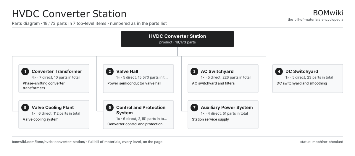
| # | Part | Qty | What it does |
|---|---|---|---|
| 1 | Converter Transformer 7 parts | 4× | Phase-shifting converter transformers |
| 2 | Valve Hall 5 parts | 1× | Power semiconductor valve hall |
| 3 | AC Switchyard 5 parts | 1× | AC switchyard and filters |
| 4 | DC Switchyard 5 parts | 1× | DC switchyard and smoothing |
| 5 | Valve Cooling Plant 6 parts | 1× | Valve cooling system |
| 6 | Control and Protection System 6 parts | 1× | Converter control and protection |
| 7 | Auxiliary Power System 4 parts | 1× | Station service supply |
3D model
No 3D model yet. Have a CAD file of this? Add a 3D model. STL renders right on this page; STEP, FreeCAD, and OpenSCAD sources are welcome too (openly licensed, like all 3D models on BOMwiki).
Build & assembly graph
expand / collapse · shared sub-assemblies converge · links to related products · est. labourTap an assembly to expand/collapse · tap a part to open it · use “Open page” for any node · drag to pan, scroll to zoom.
Bill of materials for HVDC Converter Station
7 top-level lines · 106 rows shown · 18,173 parts total · indented to 3 levels| # | Item / sub-assembly | Part no. | Qty/assy | Ext. qty | Parts | Type |
|---|---|---|---|---|---|---|
| 1 | Converter Transformer 7 parts | hcs-converter-transformer | 4× | 4 | 10 | assembly |
| 1.1 | Transformer Core | hcs-transformer-core | 1× | 4 | · | part |
| 1.2 | Converter Windings | hcs-transformer-winding | 1× | 4 | · | part |
| 1.3 | DC Wall Bushing | hcs-wall-bushing | 1× | 4 | · | part |
| 1.4 | On-Load Tap Changer | hcs-tap-changer | 1× | 4 | · | part |
| 1.5 | Transformer Tank | hcs-transformer-tank | 1× | 4 | · | part |
| 1.6 | Buchholz Relay | hcs-buchholz-relay | 1× | 4 | · | part |
| 1.7 | Oil Seal | oil-seal | 4× | 16 | · | part |
| 2 | Valve Hall 5 parts | hcs-valve-hall | 1× | 1 | 15,570 | assembly |
| 2.1 | Converter Valve Tower 5 parts | hcs-converter-valve | 6× | 6 | 2,593 | assembly |
| 2.1.1 | Thyristor Module 5 parts + deeper › | hcs-thyristor-module | 24× | 144 | 98 | assembly |
| 2.1.2 | Valve Cooling Pipe | hcs-valve-cooling-pipe | 1× | 6 | · | part |
| 2.1.3 | Valve Control Unit 4 parts + deeper › | hcs-valve-control-unit | 1× | 6 | 228 | assembly |
| 2.1.4 | Valve Suspension Insulator | hcs-suspension-insulator | 4× | 24 | · | part |
| 2.1.5 | Grading Capacitor | hcs-grading-capacitor | 8× | 48 | · | part |
| 2.2 | Valve Arrester | hcs-valve-arrester | 6× | 6 | · | part |
| 2.3 | DC Wall Bushing | hcs-wall-bushing | 4× | 4 | · | part |
| 2.4 | RF Shield Wall | hcs-rf-shield-wall | 1× | 1 | · | part |
| 2.5 | Fire Suppression System | hcs-fire-suppression | 1× | 1 | · | part |
| 3 | AC Switchyard 5 parts | hcs-ac-yard | 1× | 1 | 226 | assembly |
| 3.1 | SF6 Circuit Breaker 5 parts | ais-circuit-breaker | 2× | 2 | 41 | assembly |
| 3.1.1 | Interrupter Chamber 5 parts + deeper › | ais-interrupter-chamber | 3× | 6 | 8 | assembly |
| 3.1.2 | Operating Mechanism 6 parts + deeper › | ais-operating-mechanism | 1× | 2 | 8 | assembly |
| 3.1.3 | SF6 Density Monitor | ais-sf6-density-monitor | 3× | 6 | · | part |
| 3.1.4 | Support Insulator Column | ais-support-insulator-column | 3× | 6 | · | part |
| 3.1.5 | Grading Capacitor | ais-grading-capacitor | 3× | 6 | · | part |
| 3.2 | AC Harmonic Filter Bank 4 parts | hcs-ac-harmonic-filter | 4× | 4 | 9 | assembly |
| 3.2.1 | Filter Capacitor | hcs-filter-capacitor | 6× | 24 | · | part |
| 3.2.2 | Filter Reactor | hcs-filter-reactor | 1× | 4 | · | part |
| 3.2.3 | Filter Damping Resistor | hcs-filter-resistor | 1× | 4 | · | part |
| 3.2.4 | Filter Arrester | hcs-filter-arrester | 1× | 4 | · | part |
| 3.3 | Shunt Capacitor Bank | hcs-shunt-capacitor-bank | 2× | 2 | · | part |
| 3.4 | Substation Surge Arrester Set 3 parts | ais-surge-arrester-set | 1× | 1 | 84 | assembly |
| 3.4.1 | Metal-Oxide Arrester 3 parts + deeper › | ais-mov-arrester | 3× | 3 | 26 | assembly |
| 3.4.2 | Surge Counter | ais-surge-counter | 3× | 3 | · | part |
| 3.4.3 | Post Insulator | ais-post-insulator | 3× | 3 | · | part |
| 3.5 | Instrument Transformer Set 3 parts | ais-instrument-transformers | 1× | 1 | 22 | assembly |
| 3.5.1 | Current Transformer 4 parts + deeper › | ais-current-transformer | 3× | 3 | 4 | assembly |
| 3.5.2 | Voltage Transformer 3 parts + deeper › | ais-voltage-transformer | 3× | 3 | 3 | assembly |
| 3.5.3 | Secondary Junction Box | ais-secondary-junction-box | 1× | 1 | · | part |
| 4 | DC Switchyard 5 parts | hcs-dc-yard | 1× | 1 | 23 | assembly |
| 4.1 | Smoothing Reactor | hcs-smoothing-reactor | 1× | 1 | · | part |
| 4.2 | DC Harmonic Filter 3 parts | hcs-dc-filter | 2× | 2 | 6 | assembly |
| 4.2.1 | Filter Capacitor | hcs-filter-capacitor | 4× | 8 | · | part |
| 4.2.2 | Filter Reactor | hcs-filter-reactor | 1× | 2 | · | part |
| 4.2.3 | Filter Damping Resistor | hcs-filter-resistor | 1× | 2 | · | part |
| 4.3 | DC Disconnector | hcs-dc-disconnector | 4× | 4 | · | part |
| 4.4 | DC Pole Arrester | hcs-dc-arrester | 4× | 4 | · | part |
| 4.5 | DC Measuring Divider | hcs-dc-measuring-divider | 2× | 2 | · | part |
| 5 | Valve Cooling Plant 6 parts | hcs-cooling-plant | 1× | 1 | 112 | assembly |
| 5.1 | Coolant Circulation Pump | hcs-cooling-pump | 2× | 2 | · | part |
| 5.2 | Deionizer Column | hcs-deionizer | 1× | 1 | · | part |
| 5.3 | Outdoor Heat Exchanger | hcs-heat-exchanger | 2× | 2 | · | part |
| 5.4 | Expansion Tank | hcs-expansion-tank | 1× | 1 | · | part |
| 5.5 | Cooling Plant Controller 5 parts | hcs-cooling-control | 1× | 1 | 102 | assembly |
| 5.5.1 | Bare PCB | pcb-bare | 1× | 1 | · | part |
| 5.5.2 | Microcontroller | mcu | 1× | 1 | · | part |
| 5.5.3 | Pressure Sensor | pressure-sensor | 4× | 4 | · | part |
| 5.5.4 | Relay | relay | 6× | 6 | · | part |
| 5.5.5 | SMD Passive (R/C/L) | smd-passives | 90× | 90 | · | part |
| 5.6 | O-Ring Set | oring-set | 4× | 4 | · | part |
| 6 | Control and Protection System 6 parts | hcs-control-protection | 1× | 1 | 2,151 | assembly |
| 6.1 | Pole Control Computer 5 parts | hcs-pole-control | 2× | 2 | 347 | assembly |
| 6.1.1 | Bare PCB | pcb-bare | 3× | 6 | · | part |
| 6.1.2 | Microcontroller | mcu | 4× | 8 | · | part |
| 6.1.3 | Optical Fiber Receiver | hcs-fiber-receiver | 16× | 32 | · | part |
| 6.1.4 | SMD Passive (R/C/L) | smd-passives | 300× | 600 | · | part |
| 6.1.5 | Connector | connector | 24× | 48 | · | part |
| 6.2 | Valve Firing Controller 4 parts | hcs-firing-control | 2× | 2 | 176 | assembly |
| 6.2.1 | Bare PCB | pcb-bare | 2× | 4 | · | part |
| 6.2.2 | Microcontroller | mcu | 2× | 4 | · | part |
| 6.2.3 | Optical Fiber Receiver | hcs-fiber-receiver | 12× | 24 | · | part |
| 6.2.4 | SMD Passive (R/C/L) | smd-passives | 160× | 320 | · | part |
| 6.3 | Converter Protection Relay 6 parts | hcs-protection-relay | 4× | 4 | 219 | assembly |
| 6.3.1 | Bare PCB | pcb-bare | 2× | 8 | · | part |
| 6.3.2 | Microcontroller | mcu | 2× | 8 | · | part |
| 6.3.3 | Analog Front-End IC | afe-ic | 6× | 24 | · | part |
| 6.3.4 | Relay | relay | 8× | 32 | · | part |
| 6.3.5 | LCD Panel | lcd-panel | 1× | 4 | · | part |
| 6.3.6 | SMD Passive (R/C/L) | smd-passives | 200× | 800 | · | part |
| 6.4 | Measurement Merging Unit 4 parts | hcs-measurement-interface | 2× | 2 | 110 | assembly |
| 6.4.1 | Bare PCB | pcb-bare | 1× | 2 | · | part |
| 6.4.2 | Microcontroller | mcu | 1× | 2 | · | part |
| 6.4.3 | Optical Fiber Receiver | hcs-fiber-receiver | 8× | 16 | · | part |
| 6.4.4 | SMD Passive (R/C/L) | smd-passives | 100× | 200 | · | part |
| 6.5 | Control Cubicle | hcs-control-cubicle | 4× | 4 | · | part |
| 6.6 | Station HMI Workstation 4 parts | hcs-station-hmi | 1× | 1 | 5 | assembly |
| 6.6.1 | Power Supply | power-supply | 1× | 1 | · | part |
| 6.6.2 | LCD Panel | lcd-panel | 2× | 2 | · | part |
| 6.6.3 | Bare PCB | pcb-bare | 1× | 1 | · | part |
| 6.6.4 | Microcontroller | mcu | 1× | 1 | · | part |
| 7 | Auxiliary Power System 4 parts | hcs-auxiliary-power | 1× | 1 | 51 | assembly |
| 7.1 | Auxiliary Transformer | hcs-aux-transformer | 2× | 2 | · | part |
| 7.2 | UPS System 5 parts | hcs-ups-system | 1× | 1 | 23 | assembly |
| 7.2.1 | UPS Battery Bank | hcs-ups-battery | 1× | 1 | · | part |
| 7.2.2 | Bare PCB | pcb-bare | 1× | 1 | · | part |
| 7.2.3 | Power MOSFET | mosfet | 12× | 12 | · | part |
| 7.2.4 | Power Inductor | power-inductor | 3× | 3 | · | part |
| 7.2.5 | DC-Link Capacitor | dc-link-cap | 6× | 6 | · | part |
| 7.3 | Standby Diesel Generator 5 parts | hcs-diesel-generator | 1× | 1 | 25 | assembly |
| 7.3.1 | Diesel Engine | hcs-diesel-engine | 1× | 1 | · | part |
| 7.3.2 | Stator Assembly 3 parts + deeper › | stator-assembly | 1× | 1 | 3 | assembly |
| 7.3.3 | Rotor Assembly 4 parts + deeper › | rotor-assembly | 1× | 1 | 19 | assembly |
| 7.3.4 | Day Fuel Tank | hcs-fuel-tank | 1× | 1 | · | part |
| 7.3.5 | Radiator | radiator | 1× | 1 | · | part |
| 7.4 | Auxiliary Switchboard | hcs-aux-switchboard | 1× | 1 | · | part |
Related products
same domain, ranked by shared parts Air-Insulated Substation Bay
1,329 parts · shares 46 with this page
Air-Insulated Substation Bay
1,329 parts · shares 46 with this page
 Home Battery Storage
292 parts · shares 6 with this page
Home Battery Storage
292 parts · shares 6 with this page
 DC Fast Charger
1,097 parts · shares 6 with this page
Solar Inverter
270 parts · shares 5 with this page
DC Fast Charger
1,097 parts · shares 6 with this page
Solar Inverter
270 parts · shares 5 with this page
 Diesel Generator
147 parts · shares 13 with this page
Diesel Generator
147 parts · shares 13 with this page
 Portable Inverter Generator
96 parts · shares 14 with this page
Portable Inverter Generator
96 parts · shares 14 with this page
Sourcing: possible vendors
Browse the supplier directory → Prices, MOQ, and lead times are algorithmic estimates, not quotes, and not claims about these companies. Company mappings are curated by keyword; est. price band $5k–$50M. How estimates work| Vendor | HQ | Specialty | MOQ | Lead time |
|---|---|---|---|---|
| gevernova.com ↗ | Cambridge, US | Power generation | made to order | 20–40 wks |
| siemens-energy.com ↗ | Munich, DE | Power & grid | made to order | 20–40 wks |
| hitachienergy.com ↗ | Zurich, CH | Grid & transformers | made to order | 20–40 wks |
|
🇨🇭ABB
abb.com ↗
|
Zurich, CH | Electrification & automation | made to order | 20–40 wks |
| se.com ↗ | Rueil-Malmaison, FR | Electrical & automation | made to order | 20–40 wks |
996-word article