Combined Heat and Power Unit
ProductOverview
A combined heat and power unit, also called a cogeneration unit, burns fuel once and sells the energy twice. A reciprocating gas engine drives an electrical generator, and the heat that an ordinary generator would throw away is captured and piped to the site as hot water. Power-only generation typically converts about 40 percent of the fuel into electricity and loses the rest as warm air and hot exhaust. A CHP unit recovers most of that loss, so the total useful output reaches roughly 85 to 90 percent of the fuel energy. That single number is the reason the technology exists.
The package is built around the Gas Engine Prime Mover and the Alternator. Around them sit four heat recovery stages, a hydraulic Heating Circuit Module, a Control and Electrical cabinet, and an Acoustic Enclosure that keeps the noise in and the weather out. A unit of this kind serves hospitals, district heating schemes, greenhouses, leisure centres and any site that has a steady year-round demand for both electricity and heat.
Prime mover and generator
The engine is a spark-ignition reciprocating unit running on natural gas at a fixed 1500 rpm, which gives 50 Hz directly from a four-pole alternator. The Engine Block is a cast iron V-block with wet Cylinder Liner bores and a water jacket that doubles as the first heat source. Each cylinder carries its own Cylinder Head with two intake and two exhaust valves, and the Piston Assembly drives the Crankshaft through a forged Connecting Rod. A pair of Turbocharger units boost the air and gas charge, which lets a given engine frame make more power without growing in size.
The Alternator is a brushless synchronous machine that shares the Stator Assembly and Rotor Assembly used across the heavy rotating-machine catalogue. A Automatic Voltage Regulator holds terminal voltage steady as the load swings, and a flexible Flexible Coupling joins the alternator to the engine flywheel so torsional pulses do not crack the shafts. Mechanical power becomes electrical power here, and everything downstream of this point is about catching the heat.
Jacket water heat recovery
The first and largest low-grade heat stream comes from the engine cooling water. Instead of dumping it through a radiator, the Jacket Water Heat Recovery stage passes the hot jacket water through a Jacket Plate Exchanger, transferring the heat into the building circuit while keeping the engine coolant separate. A Jacket Water Pump circulates around 30 cubic metres per hour, and a Thermostat Valve holds the engine outlet near 90 C, which is hot enough to be useful but well below the boiling point inside the pressurized loop. The jacket water typically supplies water at 90 C flow and 70 C return, the standard temperatures for commercial heating circuits.
Exhaust gas heat recovery
The hottest energy leaves through the exhaust at 450 to 500 C, and recovering it is what separates a real CHP unit from a plain genset with a coolant tap. The Exhaust Gas Heat Recovery stage runs the gas through a Exhaust Gas Heat Exchanger, a finned tube boiler that boosts the heating water to its final temperature. Downstream of it a Condensing Economizer cools the flue gas below its dew point, condensing water vapour out of the stream and harvesting the latent heat that a conventional boiler wastes up the stack. A Exhaust Bypass Valve diverts the gas straight to atmosphere when the site cannot accept any more heat, which protects the engine from overheating during low-demand periods.
Oil, charge-air and heating circuit
Two smaller streams round out the recovery. The Lube Oil and Intercooler Recovery stage cools the lube oil through a Oil Cooler Exchanger and takes the first stage of charge-air heat through an Intercooler Exchanger, both of which preheat the return water before it reaches the jacket stage. An Lube Oil Pump built from a Helical Gear Pair keeps oil pressure at around 5 bar.
All the recovered heat collects in the Heating Circuit Module, a hydraulic skid that delivers hot water to the site. A Heating Circuit Pump drives the distribution loop, motorized three-way valves stage the flow between the recovery exchangers and the building, and an Expansion Vessel absorbs the volume change as the water heats and cools. When demand falls below the unit output, a Emergency Dump Radiator rejects the surplus so the engine can keep generating electricity even when the site needs no more heat.
Control, enclosure and exhaust
The Control and Electrical cabinet runs the whole package. A CHP Controller sequences the start, ramps the engine to speed, and a Synchronizer matches voltage, frequency and phase before the Main Circuit Breaker closes the unit onto the grid. A Protection Relay trips the breaker on grid faults, and the Power and Heat Meter tracks both exported power and delivered heat.
The complete machine sits inside an Acoustic Enclosure lined for sound, bringing the noise down to 65 to 75 dBA at one metre, and stands on Anti-Vibration Mount isolators that keep engine vibration out of the building. The spent exhaust finally passes through the Exhaust Line, where a Exhaust Silencer quiets it and a Oxidation Catalyst cleans up carbon monoxide and unburned hydrocarbons before the gas reaches the flue.
Combined Heat and Power Unit parts and their functions
9 top-level parts · 522 parts in total · full bill of materials below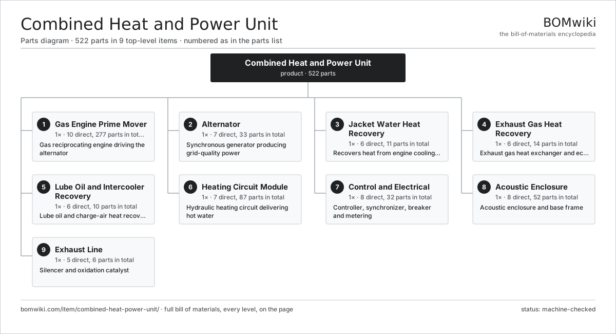
| # | Part | Qty | What it does |
|---|---|---|---|
| 1 | Gas Engine Prime Mover 10 parts | 1× | Gas reciprocating engine driving the alternator |
| 2 | Alternator 7 parts | 1× | Synchronous generator producing grid-quality power |
| 3 | Jacket Water Heat Recovery 6 parts | 1× | Recovers heat from engine cooling jacket |
| 4 | Exhaust Gas Heat Recovery 6 parts | 1× | Exhaust gas heat exchanger and economizer |
| 5 | Lube Oil and Intercooler Recovery 6 parts | 1× | Lube oil and charge-air heat recovery |
| 6 | Heating Circuit Module 7 parts | 1× | Hydraulic heating circuit delivering hot water |
| 7 | Control and Electrical 8 parts | 1× | Controller, synchronizer, breaker and metering |
| 8 | Acoustic Enclosure 8 parts | 1× | Acoustic enclosure and base frame |
| 9 | Exhaust Line 5 parts | 1× | Silencer and oxidation catalyst |
3D model
No 3D model yet. Have a CAD file of this? Add a 3D model. STL renders right on this page; STEP, FreeCAD, and OpenSCAD sources are welcome too (openly licensed, like all 3D models on BOMwiki).
Build & assembly graph
expand / collapse · shared sub-assemblies converge · links to related products · est. labourTap an assembly to expand/collapse · tap a part to open it · use “Open page” for any node · drag to pan, scroll to zoom.
Bill of materials for Combined Heat and Power Unit
9 top-level lines · 140 rows shown · 522 parts total · indented to 3 levels| # | Item / sub-assembly | Part no. | Qty/assy | Ext. qty | Parts | Type |
|---|---|---|---|---|---|---|
| 1 | Gas Engine Prime Mover 10 parts | combined-heat-power-unit-prime-mover | 1× | 1 | 277 | assembly |
| 1.1 | Engine Block 5 parts | combined-heat-power-unit-engine-block | 1× | 1 | 22 | assembly |
| 1.1.1 | Block Casting | combined-heat-power-unit-block-casting | 1× | 1 | · | part |
| 1.1.2 | Cylinder Liner | combined-heat-power-unit-cylinder-liner | 12× | 12 | · | part |
| 1.1.3 | Main Bearing Cap | combined-heat-power-unit-main-bearing-cap | 7× | 7 | · | part |
| 1.1.4 | Water Jacket Passage | combined-heat-power-unit-jacket-passage | 1× | 1 | · | part |
| 1.1.5 | O-Ring Set | oring-set | 1× | 1 | · | part |
| 1.2 | Crankshaft | combined-heat-power-unit-crankshaft | 1× | 1 | · | part |
| 1.3 | Piston Assembly 5 parts | combined-heat-power-unit-piston-assembly | 12× | 12 | 5 | assembly |
| 1.3.1 | Piston | combined-heat-power-unit-piston | 1× | 12 | · | part |
| 1.3.2 | Piston Ring Set | combined-heat-power-unit-piston-ring-set | 1× | 12 | · | part |
| 1.3.3 | Wrist Pin | combined-heat-power-unit-wrist-pin | 1× | 12 | · | part |
| 1.3.4 | Connecting Rod | combined-heat-power-unit-connecting-rod | 1× | 12 | · | part |
| 1.3.5 | Ball Bearing | ball-bearing | 1× | 12 | · | part |
| 1.4 | Cylinder Head 6 parts | combined-heat-power-unit-cylinder-head | 12× | 12 | 14 | assembly |
| 1.4.1 | Head Casting | combined-heat-power-unit-head-casting | 1× | 12 | · | part |
| 1.4.2 | Intake Valve | combined-heat-power-unit-intake-valve | 2× | 24 | · | part |
| 1.4.3 | Exhaust Valve | combined-heat-power-unit-exhaust-valve | 2× | 24 | · | part |
| 1.4.4 | Coil Spring | coil-spring | 4× | 48 | · | part |
| 1.4.5 | Valve Seat | combined-heat-power-unit-valve-seat | 4× | 48 | · | part |
| 1.4.6 | O-Ring Set | oring-set | 1× | 12 | · | part |
| 1.5 | Turbocharger 5 parts | combined-heat-power-unit-turbocharger | 2× | 2 | 7 | assembly |
| 1.5.1 | Turbine Wheel | combined-heat-power-unit-turbine-wheel | 1× | 2 | · | part |
| 1.5.2 | Compressor Wheel | combined-heat-power-unit-compressor-wheel | 1× | 2 | · | part |
| 1.5.3 | Turbocharger Housing | combined-heat-power-unit-turbo-housing | 1× | 2 | · | part |
| 1.5.4 | Ball Bearing | ball-bearing | 2× | 4 | · | part |
| 1.5.5 | Oil Seal | oil-seal | 2× | 4 | · | part |
| 1.6 | Gas Mixer | combined-heat-power-unit-gas-mixer | 1× | 1 | · | part |
| 1.7 | Ignition Module | combined-heat-power-unit-ignition-module | 1× | 1 | · | part |
| 1.8 | Ball Bearing | ball-bearing | 7× | 7 | · | part |
| 1.9 | Oil Seal | oil-seal | 2× | 2 | · | part |
| 1.10 | Fastener Set | fastener-set | 1× | 1 | · | part |
| 2 | Alternator 7 parts | combined-heat-power-unit-alternator | 1× | 1 | 33 | assembly |
| 2.1 | Stator Assembly 3 parts | stator-assembly | 1× | 1 | 3 | assembly |
| 2.1.1 | Stator Core (laminations) | stator-core | 1× | 1 | · | part |
| 2.1.2 | Copper Winding | copper-winding | 1× | 1 | · | part |
| 2.1.3 | Slot Insulation | stator-insulation | 1× | 1 | · | part |
| 2.2 | Rotor Assembly 4 parts | rotor-assembly | 1× | 1 | 19 | assembly |
| 2.2.1 | Rotor Shaft | rotor-shaft | 1× | 1 | · | part |
| 2.2.2 | Rotor Core | rotor-core | 1× | 1 | · | part |
| 2.2.3 | Neodymium Magnet | neodymium-magnet | 16× | 16 | · | part |
| 2.2.4 | Ball Bearing | ball-bearing | 1× | 1 | · | part |
| 2.3 | Brushless Exciter | combined-heat-power-unit-exciter | 1× | 1 | · | part |
| 2.4 | Automatic Voltage Regulator 4 parts | combined-heat-power-unit-avr | 1× | 1 | 6 | assembly |
| 2.4.1 | Bare PCB | pcb-bare | 1× | 1 | · | part |
| 2.4.2 | Microcontroller | mcu | 1× | 1 | · | part |
| 2.4.3 | SMD Passive (R/C/L) | smd-passives | 1× | 1 | · | part |
| 2.4.4 | Connector | connector | 3× | 3 | · | part |
| 2.5 | Alternator Housing | combined-heat-power-unit-alternator-housing | 1× | 1 | · | part |
| 2.6 | Flexible Coupling | combined-heat-power-unit-coupling | 1× | 1 | · | part |
| 2.7 | Ball Bearing | ball-bearing | 2× | 2 | · | part |
| 3 | Jacket Water Heat Recovery 6 parts | combined-heat-power-unit-jacket-water-recovery | 1× | 1 | 11 | assembly |
| 3.1 | Jacket Plate Exchanger | combined-heat-power-unit-jacket-plate-exchanger | 1× | 1 | · | part |
| 3.2 | Jacket Water Pump 4 parts | combined-heat-power-unit-jacket-water-pump | 1× | 1 | 5 | assembly |
| 3.2.1 | Pump Volute | combined-heat-power-unit-pump-volute | 1× | 1 | · | part |
| 3.2.2 | Pump Impeller | combined-heat-power-unit-pump-impeller | 1× | 1 | · | part |
| 3.2.3 | Mechanical Seal | combined-heat-power-unit-mechanical-seal | 1× | 1 | · | part |
| 3.2.4 | Ball Bearing | ball-bearing | 2× | 2 | · | part |
| 3.3 | Thermostat Valve | combined-heat-power-unit-thermostat-valve | 1× | 1 | · | part |
| 3.4 | Jacket Expansion Tank | combined-heat-power-unit-jacket-expansion-tank | 1× | 1 | · | part |
| 3.5 | Pressure Sensor | pressure-sensor | 2× | 2 | · | part |
| 3.6 | O-Ring Set | oring-set | 1× | 1 | · | part |
| 4 | Exhaust Gas Heat Recovery 6 parts | combined-heat-power-unit-exhaust-recovery | 1× | 1 | 14 | assembly |
| 4.1 | Exhaust Gas Heat Exchanger 5 parts | combined-heat-power-unit-exhaust-gas-exchanger | 1× | 1 | 6 | assembly |
| 4.1.1 | Exchanger Shell | combined-heat-power-unit-exchanger-shell | 1× | 1 | · | part |
| 4.1.2 | Exchanger Tube Bundle | combined-heat-power-unit-exchanger-tube-bundle | 1× | 1 | · | part |
| 4.1.3 | Exchanger Tube Plate | combined-heat-power-unit-exchanger-tube-plate | 2× | 2 | · | part |
| 4.1.4 | Soot Blower | combined-heat-power-unit-soot-blower | 1× | 1 | · | part |
| 4.1.5 | O-Ring Set | oring-set | 1× | 1 | · | part |
| 4.2 | Condensing Economizer 3 parts | combined-heat-power-unit-condensing-economizer | 1× | 1 | 3 | assembly |
| 4.2.1 | Economizer Core | combined-heat-power-unit-economizer-core | 1× | 1 | · | part |
| 4.2.2 | Condensate Trap | combined-heat-power-unit-condensate-trap | 1× | 1 | · | part |
| 4.2.3 | Economizer Shell | combined-heat-power-unit-economizer-shell | 1× | 1 | · | part |
| 4.3 | Exhaust Bypass Valve | combined-heat-power-unit-exhaust-bypass-valve | 1× | 1 | · | part |
| 4.4 | Exhaust Temperature Sensor | combined-heat-power-unit-exhaust-temp-sensor | 2× | 2 | · | part |
| 4.5 | Pressure Sensor | pressure-sensor | 1× | 1 | · | part |
| 4.6 | Fastener Set | fastener-set | 1× | 1 | · | part |
| 5 | Lube Oil and Intercooler Recovery 6 parts | combined-heat-power-unit-oil-intercooler-recovery | 1× | 1 | 10 | assembly |
| 5.1 | Oil Cooler Exchanger | combined-heat-power-unit-oil-cooler-exchanger | 1× | 1 | · | part |
| 5.2 | Intercooler Exchanger | combined-heat-power-unit-intercooler-exchanger | 1× | 1 | · | part |
| 5.3 | Lube Oil Pump 4 parts | combined-heat-power-unit-oil-pump | 1× | 1 | 4 | assembly |
| 5.3.1 | Helical Gear Pair | gear-pair | 1× | 1 | · | part |
| 5.3.2 | Gearbox Housing | gearbox-housing | 1× | 1 | · | part |
| 5.3.3 | Relief Valve | combined-heat-power-unit-relief-valve | 1× | 1 | · | part |
| 5.3.4 | Oil Seal | oil-seal | 1× | 1 | · | part |
| 5.4 | Oil Filter | combined-heat-power-unit-oil-filter | 2× | 2 | · | part |
| 5.5 | Oil Thermostat | combined-heat-power-unit-oil-thermostat | 1× | 1 | · | part |
| 5.6 | O-Ring Set | oring-set | 1× | 1 | · | part |
| 6 | Heating Circuit Module 7 parts | combined-heat-power-unit-heating-module | 1× | 1 | 87 | assembly |
| 6.1 | Heating Circuit Pump 4 parts | combined-heat-power-unit-heating-pump | 1× | 1 | 28 | assembly |
| 6.1.1 | Pump Volute | combined-heat-power-unit-pump-volute | 1× | 1 | · | part |
| 6.1.2 | Pump Impeller | combined-heat-power-unit-pump-impeller | 1× | 1 | · | part |
| 6.1.3 | Servo Motor 4 parts + deeper › | servo-motor | 1× | 1 | 24 | assembly |
| 6.1.4 | Ball Bearing | ball-bearing | 2× | 2 | · | part |
| 6.2 | Three-Way Valve | combined-heat-power-unit-three-way-valve | 2× | 2 | · | part |
| 6.3 | Expansion Vessel | combined-heat-power-unit-expansion-vessel | 1× | 1 | · | part |
| 6.4 | Emergency Dump Radiator 4 parts | combined-heat-power-unit-dump-radiator | 1× | 1 | 52 | assembly |
| 6.4.1 | Radiator Core | combined-heat-power-unit-radiator-core | 1× | 1 | · | part |
| 6.4.2 | Servo Motor 4 parts + deeper › | servo-motor | 2× | 2 | 24 | assembly |
| 6.4.3 | Fan Blade | combined-heat-power-unit-fan-blade | 2× | 2 | · | part |
| 6.4.4 | Three-Way Valve | combined-heat-power-unit-three-way-valve | 1× | 1 | · | part |
| 6.5 | Hydraulic Separator | combined-heat-power-unit-plate-buffer-exchanger | 1× | 1 | · | part |
| 6.6 | Pressure Sensor | pressure-sensor | 2× | 2 | · | part |
| 6.7 | Heat Flow Meter | combined-heat-power-unit-flow-meter | 1× | 1 | · | part |
| 7 | Control and Electrical 8 parts | combined-heat-power-unit-control-electrical | 1× | 1 | 32 | assembly |
| 7.1 | CHP Controller 5 parts | combined-heat-power-unit-controller | 1× | 1 | 10 | assembly |
| 7.1.1 | Bare PCB | pcb-bare | 1× | 1 | · | part |
| 7.1.2 | Microcontroller | mcu | 1× | 1 | · | part |
| 7.1.3 | SMD Passive (R/C/L) | smd-passives | 1× | 1 | · | part |
| 7.1.4 | LCD Panel | lcd-panel | 1× | 1 | · | part |
| 7.1.5 | Connector | connector | 6× | 6 | · | part |
| 7.2 | Synchronizer 4 parts | combined-heat-power-unit-synchronizer | 1× | 1 | 6 | assembly |
| 7.2.1 | Bare PCB | pcb-bare | 1× | 1 | · | part |
| 7.2.2 | Microcontroller | mcu | 1× | 1 | · | part |
| 7.2.3 | Relay | relay | 2× | 2 | · | part |
| 7.2.4 | Connector | connector | 2× | 2 | · | part |
| 7.3 | Main Circuit Breaker | combined-heat-power-unit-breaker | 1× | 1 | · | part |
| 7.4 | Power and Heat Meter | combined-heat-power-unit-metering | 1× | 1 | · | part |
| 7.5 | Protection Relay | combined-heat-power-unit-protection-relay | 1× | 1 | · | part |
| 7.6 | Power Supply | power-supply | 1× | 1 | · | part |
| 7.7 | Wire Bundle | wire-bundle | 4× | 4 | · | part |
| 7.8 | Relay | relay | 8× | 8 | · | part |
| 8 | Acoustic Enclosure 8 parts | combined-heat-power-unit-enclosure | 1× | 1 | 52 | assembly |
| 8.1 | Base Frame | combined-heat-power-unit-base-frame | 1× | 1 | · | part |
| 8.2 | Sheet Metal Panel | sheet-panel | 12× | 12 | · | part |
| 8.3 | Acoustic Liner | combined-heat-power-unit-acoustic-liner | 1× | 1 | · | part |
| 8.4 | Intake Attenuator | combined-heat-power-unit-intake-attenuator | 1× | 1 | · | part |
| 8.5 | Extract Attenuator | combined-heat-power-unit-extract-attenuator | 1× | 1 | · | part |
| 8.6 | Ventilation Fan 3 parts | combined-heat-power-unit-vent-fan | 1× | 1 | 27 | assembly |
| 8.6.1 | Servo Motor 4 parts + deeper › | servo-motor | 1× | 1 | 24 | assembly |
| 8.6.2 | Fan Blade | combined-heat-power-unit-fan-blade | 1× | 1 | · | part |
| 8.6.3 | Ball Bearing | ball-bearing | 2× | 2 | · | part |
| 8.7 | Anti-Vibration Mount | combined-heat-power-unit-anti-vibration-mount | 8× | 8 | · | part |
| 8.8 | Fastener Set | fastener-set | 1× | 1 | · | part |
| 9 | Exhaust Line 5 parts | combined-heat-power-unit-exhaust-line | 1× | 1 | 6 | assembly |
| 9.1 | Exhaust Silencer | combined-heat-power-unit-silencer | 1× | 1 | · | part |
| 9.2 | Oxidation Catalyst | combined-heat-power-unit-oxidation-catalyst | 1× | 1 | · | part |
| 9.3 | Exhaust Bellows | combined-heat-power-unit-exhaust-bellows | 2× | 2 | · | part |
| 9.4 | Lambda Sensor | combined-heat-power-unit-lambda-sensor | 1× | 1 | · | part |
| 9.5 | Fastener Set | fastener-set | 1× | 1 | · | part |
Related products
same domain, ranked by shared parts Coal Pulverizer Mill
313 parts · shares 20 with this page
Coal Pulverizer Mill
313 parts · shares 20 with this page
 Large Power Transformer
1,844 parts · shares 20 with this page
Large Power Transformer
1,844 parts · shares 20 with this page
 Industrial Gas Turbine Package
2,053 parts · shares 19 with this page
Industrial Gas Turbine Package
2,053 parts · shares 19 with this page
 Automatic Voltage Regulator
83 parts · shares 18 with this page
Automatic Voltage Regulator
83 parts · shares 18 with this page
 Air-Insulated Substation Bay
1,329 parts · shares 19 with this page
Air-Insulated Substation Bay
1,329 parts · shares 19 with this page
Sourcing: possible vendors
Browse the supplier directory → Prices, MOQ, and lead times are algorithmic estimates, not quotes, and not claims about these companies. Company mappings are curated by keyword; est. price band $5k–$50M. How estimates work| Vendor | HQ | Specialty | MOQ | Lead time |
|---|---|---|---|---|
| gevernova.com ↗ | Cambridge, US | Power generation | made to order | 20–40 wks |
| siemens-energy.com ↗ | Munich, DE | Power & grid | made to order | 20–40 wks |
| hitachienergy.com ↗ | Zurich, CH | Grid & transformers | made to order | 20–40 wks |
|
🇨🇭ABB
abb.com ↗
|
Zurich, CH | Electrification & automation | made to order | 20–40 wks |
| se.com ↗ | Rueil-Malmaison, FR | Electrical & automation | made to order | 20–40 wks |
1,021-word article