Phase-Shifting Transformer
ProductOverview
A phase-shifting transformer, often shortened to PST, is a power apparatus that controls the flow of real power on a transmission line by changing the phase angle between its source-side and load-side voltages rather than their magnitude. Power flow between two points on an AC grid is governed largely by the angular difference across the line, so inserting a controllable angle in series with the line steers how much power takes that path. Operators use PSTs to relieve overloaded corridors, to balance loading across parallel circuits, and to control flow across interconnection boundaries. Ratings commonly fall between 200 and 1,800 MVA at system voltages from 110 to 500 kV, with a controllable shift of roughly plus or minus 20 to plus or minus 40 degrees.
The unit described here is a two-core design. An Exciting Transformer Core and Windings draws voltage from the line and supplies a regulated, tapped voltage. A separate Series Transformer Core and Windings injects that voltage in series with the line, oriented in quadrature so it rotates the load-side phasor. Splitting the function across two cores keeps the on-load tap changer at a manageable voltage and current and isolates it from the full line insulation level.
How it works: phase angle control
The exciting unit primary winding is connected across the source phases. Its Exciting Regulating Winding regulating winding feeds the tap changer, which selects how many turns are in circuit. The output then drives the Series Excited Winding of the series unit. Because of the delta arrangement set by the Delta Interconnection Board, the voltage injected into each phase is taken from the other two phases, so it sits about 90 degrees away from the phase being corrected. Adding a quadrature voltage to the line voltage rotates the resultant, producing a phase shift whose size depends on how much voltage the tap changer admits.
The injected angle is set in discrete steps. A typical unit offers 17 to 33 tap positions giving 1.0 to 1.5 degrees of shift per step. The Tap Position Controller commands tap moves to hold a target angle or a target megawatt flow, and a reversing selector flips the polarity of the regulating winding so the same taps serve both advance and retard. Advance taps push more power onto the controlled line; retard taps divert power away from it.
On-load tap changer
The On-Load Tap Changer changes taps while the unit carries full load current, so it cannot simply open one tap and close the next. Its diverter switch uses transition resistors to bridge two taps for a few milliseconds, limiting the circulating current during transfer. The selector contacts pre-position the next tap before the diverter acts, and the change-over selector handles the advance-to-retard crossover. A motor drive turns the mechanism through a gear train, with arcing confined to a sealed oil compartment so its degraded oil never mixes with the main-tank oil. PST tap changers carry full line current rather than the smaller regulating current of an ordinary voltage regulator, which is why they are built for high current and rated for around 200,000 mechanical operations.
Subsystems and materials
Both cores are stacked from grain-oriented silicon steel laminations, clamped in steel frames, and wound with copper conductor insulated by oil-impregnated pressboard. The active parts sit in the Tank, Oil and Pressure Relief, filled with 40,000 to 90,000 liters of mineral insulating oil that provides both dielectric strength and heat transfer. Line conductors pass through the Bushings, a set of condenser bushings for the source, load, and neutral terminals. Internally, the Interconnecting Bus and Links of insulated copper links and bus supports joins the exciting taps to the series winding circuit, and bushing current transformers feed the protection scheme.
Losses heat the oil, so a Cooling Radiators and Pumps bank of 8 to 12 panel radiators, oil pumps, and fans moves heat to ambient air. Cooling runs in stages, natural circulation at light load and forced oil with forced air near rating, holding top-oil rise to about 55 K and winding rise to about 65 K over ambient. The Conservator and Oil Preservation accommodates the oil volume change between cold and hot operation and uses a silica gel breather to keep moisture out, with a separate compartment for the tap changer oil.
Protection and control
Because a PST is large and costly, it carries layered protection. The Protection Relays and Monitoring subsystem includes a Buchholz gas relay on the conservator pipe, an oil-surge relay on the tap changer, winding and oil temperature indicators, sudden-pressure sensors, and differential and overcurrent relays. An online dissolved-gas monitor trends fault gases so slow deterioration is caught before it becomes a failure. All of this terminates in the Control and Cooling Cabinet, which houses the tap logic, the cooling stage controller, an anti-condensation heater, and the field wiring.
Variants
PSTs are classified by how the injected voltage relates to the line voltage. A symmetrical design keeps the load-side voltage magnitude equal to the source-side magnitude across the whole tap range, so only the angle changes; an asymmetrical design lets the magnitude vary as the angle is set, which is simpler but couples voltage to flow control. They are also classified by construction. A single-core design combines exciting and series functions in one tank and suits smaller ratings and modest shift angles. A two-core design, used here, separates the functions so the tap changer sees a reduced duty and the insulation can be coordinated for high voltage and high MVA. Single-phase banks of three units are sometimes used for the largest ratings or where transport mass must be kept under shipping limits, since a complete three-phase unit can exceed 400,000 kg.
Phase-Shifting Transformer parts and their functions
10 top-level parts · 203 parts in total · full bill of materials below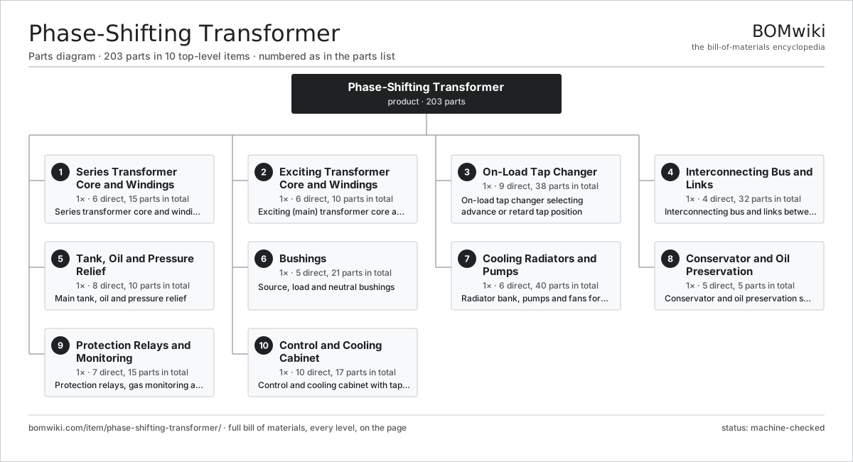
| # | Part | Qty | What it does |
|---|---|---|---|
| 1 | Series Transformer Core and Windings 6 parts | 1× | Series transformer core and windings injecting the quadrature voltage |
| 2 | Exciting Transformer Core and Windings 6 parts | 1× | Exciting (main) transformer core and windings supplying regulated source voltage |
| 3 | On-Load Tap Changer 9 parts | 1× | On-load tap changer selecting advance or retard tap position |
| 4 | Interconnecting Bus and Links 4 parts | 1× | Interconnecting bus and links between the two cores |
| 5 | Tank, Oil and Pressure Relief 8 parts | 1× | Main tank, oil and pressure relief |
| 6 | Bushings 5 parts | 1× | Source, load and neutral bushings |
| 7 | Cooling Radiators and Pumps 6 parts | 1× | Radiator bank, pumps and fans for oil cooling |
| 8 | Conservator and Oil Preservation 5 parts | 1× | Conservator and oil preservation system |
| 9 | Protection Relays and Monitoring 7 parts | 1× | Protection relays, gas monitoring and instrumentation |
| 10 | Control and Cooling Cabinet 10 parts | 1× | Control and cooling cabinet with tap-position logic |
3D model
No 3D model yet. Have a CAD file of this? Add a 3D model. STL renders right on this page; STEP, FreeCAD, and OpenSCAD sources are welcome too (openly licensed, like all 3D models on BOMwiki).
Build & assembly graph
expand / collapse · shared sub-assemblies converge · links to related products · est. labourTap an assembly to expand/collapse · tap a part to open it · use “Open page” for any node · drag to pan, scroll to zoom.
Bill of materials for Phase-Shifting Transformer
10 top-level lines · 80 rows shown · 203 parts total · indented to 3 levels| # | Item / sub-assembly | Part no. | Qty/assy | Ext. qty | Parts | Type |
|---|---|---|---|---|---|---|
| 1 | Series Transformer Core and Windings 6 parts | phase-shifting-transformer-series-unit | 1× | 1 | 15 | assembly |
| 1.1 | Series Unit Core | phase-shifting-transformer-series-core | 1× | 1 | · | part |
| 1.2 | Series Line Winding | phase-shifting-transformer-series-primary | 3× | 3 | · | part |
| 1.3 | Series Excited Winding | phase-shifting-transformer-series-secondary | 3× | 3 | · | part |
| 1.4 | Series Core Clamping Frame | phase-shifting-transformer-series-clamping | 1× | 1 | · | part |
| 1.5 | Series Insulation Barriers | phase-shifting-transformer-series-insulation | 1× | 1 | · | part |
| 1.6 | Winding Lead Exit | phase-shifting-transformer-lead-exit | 6× | 6 | · | part |
| 2 | Exciting Transformer Core and Windings 6 parts | phase-shifting-transformer-exciting-unit | 1× | 1 | 10 | assembly |
| 2.1 | Exciting Unit Core | phase-shifting-transformer-exciting-core | 1× | 1 | · | part |
| 2.2 | Exciting Primary Winding | phase-shifting-transformer-exciting-primary | 3× | 3 | · | part |
| 2.3 | Exciting Regulating Winding | phase-shifting-transformer-exciting-tapped | 3× | 3 | · | part |
| 2.4 | Exciting Core Clamping Frame | phase-shifting-transformer-exciting-clamping | 1× | 1 | · | part |
| 2.5 | Exciting Insulation Barriers | phase-shifting-transformer-exciting-insulation | 1× | 1 | · | part |
| 2.6 | Delta Interconnection Board | phase-shifting-transformer-delta-connection | 1× | 1 | · | part |
| 3 | On-Load Tap Changer 9 parts | phase-shifting-transformer-oltc | 1× | 1 | 38 | assembly |
| 3.1 | OLTC Diverter Switch | phase-shifting-transformer-oltc-diverter | 1× | 1 | · | part |
| 3.2 | OLTC Tap Selector | phase-shifting-transformer-oltc-selector | 1× | 1 | · | part |
| 3.3 | OLTC Reversing Selector | phase-shifting-transformer-oltc-reversing | 1× | 1 | · | part |
| 3.4 | OLTC Transition Resistor | phase-shifting-transformer-oltc-resistor | 6× | 6 | · | part |
| 3.5 | OLTC Motor Drive Unit | phase-shifting-transformer-oltc-drive | 1× | 1 | · | part |
| 3.6 | Servo Motor 4 parts | servo-motor | 1× | 1 | 24 | assembly |
| 3.6.1 | Stator Assembly 3 parts + deeper › | stator-assembly | 1× | 1 | 3 | assembly |
| 3.6.2 | Rotor Assembly 4 parts + deeper › | rotor-assembly | 1× | 1 | 19 | assembly |
| 3.6.3 | Encoder | encoder | 1× | 1 | · | part |
| 3.6.4 | Motor Housing | motor-housing | 1× | 1 | · | part |
| 3.7 | Helical Gear Pair | gear-pair | 2× | 2 | · | part |
| 3.8 | OLTC Oil Compartment | phase-shifting-transformer-oltc-compartment | 1× | 1 | · | part |
| 3.9 | OLTC Position Indicator | phase-shifting-transformer-oltc-counter | 1× | 1 | · | part |
| 4 | Interconnecting Bus and Links 4 parts | phase-shifting-transformer-interconnect | 1× | 1 | 32 | assembly |
| 4.1 | Interphase Link | phase-shifting-transformer-interphase-link | 6× | 6 | · | part |
| 4.2 | Internal Bus Support | phase-shifting-transformer-bus-support | 8× | 8 | · | part |
| 4.3 | Bushing Current Transformer | phase-shifting-transformer-ct | 6× | 6 | · | part |
| 4.4 | Connector | connector | 12× | 12 | · | part |
| 5 | Tank, Oil and Pressure Relief 8 parts | phase-shifting-transformer-tank | 1× | 1 | 10 | assembly |
| 5.1 | Main Tank | phase-shifting-transformer-main-tank | 1× | 1 | · | part |
| 5.2 | Tank Cover | phase-shifting-transformer-tank-cover | 1× | 1 | · | part |
| 5.3 | Insulating Oil | phase-shifting-transformer-oil | 1× | 1 | · | part |
| 5.4 | O-Ring Set | oring-set | 1× | 1 | · | part |
| 5.5 | Pressure Relief Device | phase-shifting-transformer-pressure-relief | 2× | 2 | · | part |
| 5.6 | Drain and Sampling Valve | phase-shifting-transformer-drain-valve | 2× | 2 | · | part |
| 5.7 | Fastener Set | fastener-set | 1× | 1 | · | part |
| 5.8 | Base Skid | phase-shifting-transformer-base-skid | 1× | 1 | · | part |
| 6 | Bushings 5 parts | phase-shifting-transformer-bushings | 1× | 1 | 21 | assembly |
| 6.1 | Source Bushing | phase-shifting-transformer-source-bushing | 3× | 3 | · | part |
| 6.2 | Load Bushing | phase-shifting-transformer-load-bushing | 3× | 3 | · | part |
| 6.3 | Neutral Bushing | phase-shifting-transformer-neutral-bushing | 1× | 1 | · | part |
| 6.4 | Bushing Turret | phase-shifting-transformer-bushing-turret | 7× | 7 | · | part |
| 6.5 | Oil Seal | oil-seal | 7× | 7 | · | part |
| 7 | Cooling Radiators and Pumps 6 parts | phase-shifting-transformer-cooling | 1× | 1 | 40 | assembly |
| 7.1 | Panel Radiator | phase-shifting-transformer-radiator | 8× | 8 | · | part |
| 7.2 | Oil Circulation Pump | phase-shifting-transformer-oil-pump | 2× | 2 | · | part |
| 7.3 | Radiator Cooling Fan | phase-shifting-transformer-cooling-fan | 8× | 8 | · | part |
| 7.4 | Oil Flow Indicator | phase-shifting-transformer-flow-indicator | 2× | 2 | · | part |
| 7.5 | Radiator Isolating Valve | phase-shifting-transformer-radiator-valve | 16× | 16 | · | part |
| 7.6 | Ball Bearing | ball-bearing | 4× | 4 | · | part |
| 8 | Conservator and Oil Preservation 5 parts | phase-shifting-transformer-conservator | 1× | 1 | 5 | assembly |
| 8.1 | Conservator Tank | phase-shifting-transformer-conservator-tank | 1× | 1 | · | part |
| 8.2 | Air Cell | phase-shifting-transformer-rubber-bag | 1× | 1 | · | part |
| 8.3 | Silica Gel Breather | phase-shifting-transformer-breather | 1× | 1 | · | part |
| 8.4 | Magnetic Oil Level Gauge | phase-shifting-transformer-magnetic-gauge | 1× | 1 | · | part |
| 8.5 | OLTC Conservator Compartment | phase-shifting-transformer-oltc-conservator | 1× | 1 | · | part |
| 9 | Protection Relays and Monitoring 7 parts | phase-shifting-transformer-protection | 1× | 1 | 15 | assembly |
| 9.1 | Buchholz Relay | phase-shifting-transformer-buchholz | 1× | 1 | · | part |
| 9.2 | OLTC Oil-Surge Relay | phase-shifting-transformer-oltc-protection-relay | 1× | 1 | · | part |
| 9.3 | Winding Temperature Indicator | phase-shifting-transformer-wti | 2× | 2 | · | part |
| 9.4 | Oil Temperature Indicator | phase-shifting-transformer-oti | 1× | 1 | · | part |
| 9.5 | Pressure Sensor | pressure-sensor | 3× | 3 | · | part |
| 9.6 | Relay | relay | 6× | 6 | · | part |
| 9.7 | Dissolved-Gas Monitor | phase-shifting-transformer-gas-monitor | 1× | 1 | · | part |
| 10 | Control and Cooling Cabinet 10 parts | phase-shifting-transformer-control-cabinet | 1× | 1 | 17 | assembly |
| 10.1 | Tap Position Controller | phase-shifting-transformer-tap-controller | 1× | 1 | · | part |
| 10.2 | Cooling Stage Controller | phase-shifting-transformer-cooling-control | 1× | 1 | · | part |
| 10.3 | Control Cabinet Enclosure | phase-shifting-transformer-cabinet-enclosure | 1× | 1 | · | part |
| 10.4 | Heating Element | heating-element | 1× | 1 | · | part |
| 10.5 | Power Supply | power-supply | 1× | 1 | · | part |
| 10.6 | Microcontroller | mcu | 1× | 1 | · | part |
| 10.7 | Bare PCB | pcb-bare | 1× | 1 | · | part |
| 10.8 | SMD Passive (R/C/L) | smd-passives | 1× | 1 | · | part |
| 10.9 | Wire Bundle | wire-bundle | 1× | 1 | · | part |
| 10.10 | Relay | relay | 8× | 8 | · | part |
Related products
same domain, ranked by shared parts SCR NOx Reduction Unit
569 parts · shares 19 with this page
SCR NOx Reduction Unit
569 parts · shares 19 with this page
 Coal Pulverizer Mill
313 parts · shares 18 with this page
Coal Pulverizer Mill
313 parts · shares 18 with this page
 Gas-Insulated Switchgear
281 parts · shares 18 with this page
Bottom Ash Handling System
1,782 parts · shares 18 with this page
Gas-Insulated Switchgear
281 parts · shares 18 with this page
Bottom Ash Handling System
1,782 parts · shares 18 with this page
 Combined Heat and Power Unit
522 parts · shares 18 with this page
Combined Heat and Power Unit
522 parts · shares 18 with this page
 Air-Insulated Substation Bay
1,329 parts · shares 17 with this page
Air-Insulated Substation Bay
1,329 parts · shares 17 with this page
Sourcing: possible vendors
Browse the supplier directory → Prices, MOQ, and lead times are algorithmic estimates, not quotes, and not claims about these companies. Company mappings are curated by keyword; est. price band $5k–$50M. How estimates work| Vendor | HQ | Specialty | MOQ | Lead time |
|---|---|---|---|---|
| gevernova.com ↗ | Cambridge, US | Power generation | made to order | 20–40 wks |
| siemens-energy.com ↗ | Munich, DE | Power & grid | made to order | 20–40 wks |
| hitachienergy.com ↗ | Zurich, CH | Grid & transformers | made to order | 20–40 wks |
|
🇨🇭ABB
abb.com ↗
|
Zurich, CH | Electrification & automation | made to order | 20–40 wks |
| se.com ↗ | Rueil-Malmaison, FR | Electrical & automation | made to order | 20–40 wks |
989-word article