HV Transmission Tower
ProductOverview
A high-voltage transmission tower is the steel lattice structure that holds overhead power lines aloft between substations. Its job sounds simple, keep the conductors a safe distance above the ground and apart from each other and the steel, but it must do so for sixty years through wind, ice, and temperature swings, across mountains, rivers, and farmland, while carrying its own weight and the pull of conductors stretching hundreds of meters to the next tower. The lattice form wins because it presents little area to the wind, uses steel efficiently, and can be bolted together by hand in remote terrain.
The tower is made of a tapering tower body, a cross arm set that holds the phases, a peak section carrying the lightning shield wire, four leg foundations, the insulator strings that hang the conductors, an earthing system, and assorted fittings.
Structure and Load Path
Every load on the tower ends up in the ground through the tower body. The four main leg members, hot-rolled steel angles, are the primary compression elements, set at the corners and tapering inward as they rise so the wide base resists overturning. Between the legs, bracing members triangulate each face: a triangle cannot change shape without changing the length of its sides, so the bracing turns a flexible frame into a rigid truss. Long members would buckle under compression, so redundant members shorten their unsupported length without carrying primary load. Members meet at gusset plates that spread the bolt forces, and where the ground slopes, a leg stub extension lets each leg be set to a different length so the body stays level.
Holding the Conductors
The conductors must hang clear of the steel, which is the function of the cross arm set. Each cross arm is a lattice cantilever projecting horizontally to carry one phase out beyond the body. The downward conductor weight and ice load put the lower arm members in compression and the tie members in tension. At the arm tip, a forged attachment point receives the insulator string. Spacing between arms is set by the voltage: higher voltage means a larger air gap, so a 765 kV tower has far wider and taller arm geometry than a 132 kV one.
Insulation and Conductor Support
The conductor hangs from each arm on a suspension insulator string. The string is a stack of insulator discs, glass or composite, whose count is chosen for the voltage and the local pollution level: more discs give more creepage distance so salt or dust films cannot bridge them. A corona ring grades the electric field at the live end to stop the buzzing discharge that erodes hardware and creates radio noise, and an arcing horn gives a flashover somewhere safe to strike rather than across the insulator surface. At the bottom, a suspension clamp grips the conductor, and a vibration damper near the clamp soaks up the steady wind-driven oscillation that would otherwise fatigue the aluminum strands where they enter the clamp.
Lightning Protection
Towers are tall metal objects in open country, so they are struck by lightning often. The peak section carries an overhead shield wire on the earthwire peak, positioned at a shielding angle so a downward stroke hits the shield wire rather than a phase conductor. The strike current then needs a low-resistance path to ground, which is why the earthing system matters. Radial counterpoise wires and driven earth rods, bonded to each leg by an earth clamp, lower the footing resistance. If that resistance is too high, the tower potential rises so far during a strike that it flashes back across the insulator onto the phase, a back-flashover, which the low footing resistance is designed to prevent.
Foundations
Wind on the tower and the pull of the conductors try to lift one pair of legs and push down the other, so each leg foundation resists both compression and uplift. The reinforced concrete footing is a pad-and-chimney design; the pad bears on the soil for compression while the weight of soil and concrete resists uplift. A galvanized stub angle is cast into the concrete for the leg to bolt onto, tied into a reinforcement cage and an anchor cleat that transfer uplift into the footing.
Variants and Use
Tower types are defined by their function along a line. Suspension towers, the common type, simply carry the conductor weight on a vertical string. Tension or angle towers, built far heavier, take the full conductor pull where the line changes direction or terminates, using horizontal tension strings. Terrain drives the rest: river crossings use exceptionally tall towers, and double-circuit designs stack two three-phase circuits to halve right-of-way. Monopole and tubular structures are replacing lattice in suburban areas for appearance, but the bolted lattice tower remains the economic choice for long overhead transmission lines because it is light, strong, and assembled with simple tools far from any road.
HV Transmission Tower parts and their functions
7 top-level parts · 239 parts in total · full bill of materials below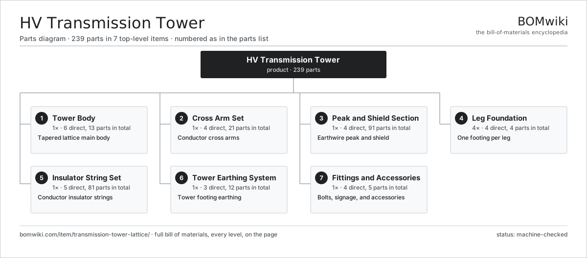
| # | Part | Qty | What it does |
|---|---|---|---|
| 1 | Tower Body 6 parts | 1× | Tapered lattice main body |
| 2 | Cross Arm Set 4 parts | 1× | Conductor cross arms |
| 3 | Peak and Shield Section 4 parts | 1× | Earthwire peak and shield |
| 4 | Leg Foundation 4 parts | 4× | One footing per leg |
| 5 | Insulator String Set 5 parts | 1× | Conductor insulator strings |
| 6 | Tower Earthing System 3 parts | 1× | Tower footing earthing |
| 7 | Fittings and Accessories 4 parts | 1× | Bolts, signage, and accessories |
3D model
No 3D model yet. Have a CAD file of this? Add a 3D model. STL renders right on this page; STEP, FreeCAD, and OpenSCAD sources are welcome too (openly licensed, like all 3D models on BOMwiki).
Build & assembly graph
expand / collapse · shared sub-assemblies converge · links to related products · est. labourTap an assembly to expand/collapse · tap a part to open it · use “Open page” for any node · drag to pan, scroll to zoom.
Bill of materials for HV Transmission Tower
7 top-level lines · 44 rows shown · 239 parts total · indented to 3 levels| # | Item / sub-assembly | Part no. | Qty/assy | Ext. qty | Parts | Type |
|---|---|---|---|---|---|---|
| 1 | Tower Body 6 parts | ttl-tower-body | 1× | 1 | 13 | assembly |
| 1.1 | Main Leg Member | ttl-leg-member | 4× | 4 | · | part |
| 1.2 | Bracing Member | ttl-bracing-member | 1× | 1 | · | part |
| 1.3 | Redundant Member | ttl-redundant-member | 1× | 1 | · | part |
| 1.4 | Gusset Plate | ttl-gusset-plate | 1× | 1 | · | part |
| 1.5 | Leg Stub Extension | ttl-leg-extension | 4× | 4 | · | part |
| 1.6 | Fastener Set | fastener-set | 2× | 2 | · | part |
| 2 | Cross Arm Set 4 parts | ttl-cross-arm-set | 1× | 1 | 21 | assembly |
| 2.1 | Cross Arm | ttl-cross-arm | 6× | 6 | · | part |
| 2.2 | Arm Tie Member | ttl-arm-tie-member | 6× | 6 | · | part |
| 2.3 | Conductor Attachment Point | ttl-conductor-attachment | 3× | 3 | · | part |
| 2.4 | Gusset Plate | ttl-gusset-plate | 6× | 6 | · | part |
| 3 | Peak and Shield Section 4 parts | ttl-peak-section | 1× | 1 | 91 | assembly |
| 3.1 | Earthwire Peak | ttl-earthwire-peak | 1× | 1 | · | part |
| 3.2 | Earthwire Clamp | ttl-earthwire-clamp | 2× | 2 | · | part |
| 3.3 | Aviation Obstruction Light 4 parts | ttl-aviation-light | 2× | 2 | 43 | assembly |
| 3.3.1 | Bare PCB | pcb-bare | 1× | 2 | · | part |
| 3.3.2 | Microcontroller | mcu | 1× | 2 | · | part |
| 3.3.3 | Power Supply | power-supply | 1× | 2 | · | part |
| 3.3.4 | SMD Passive (R/C/L) | smd-passives | 40× | 80 | · | part |
| 3.4 | Aircraft Warning Sphere | ttl-aircraft-warning-sphere | 2× | 2 | · | part |
| 4 | Leg Foundation 4 parts | ttl-foundation-set | 4× | 4 | 4 | assembly |
| 4.1 | Concrete Footing | ttl-concrete-footing | 1× | 4 | · | part |
| 4.2 | Stub Angle | ttl-stub-angle | 1× | 4 | · | part |
| 4.3 | Reinforcement Cage | ttl-rebar-cage | 1× | 4 | · | part |
| 4.4 | Anchor Cleat | ttl-anchor-cleat | 1× | 4 | · | part |
| 5 | Insulator String Set 5 parts | ttl-insulator-assembly-set | 1× | 1 | 81 | assembly |
| 5.1 | Suspension Insulator String 3 parts | ttl-suspension-string | 3× | 3 | 21 | assembly |
| 5.1.1 | Insulator Disc | ttl-insulator-disc | 18× | 54 | · | part |
| 5.1.2 | Yoke Plate | ttl-yoke-plate | 1× | 3 | · | part |
| 5.1.3 | Ball-and-Socket Link | ais-ball-socket-link | 2× | 6 | · | part |
| 5.2 | Corona Ring | ttl-corona-ring | 3× | 3 | · | part |
| 5.3 | Arcing Horn | ttl-arcing-horn | 6× | 6 | · | part |
| 5.4 | Suspension Clamp | ttl-suspension-clamp | 3× | 3 | · | part |
| 5.5 | Vibration Damper | ttl-vibration-damper | 6× | 6 | · | part |
| 6 | Tower Earthing System 3 parts | ttl-earthing-system | 1× | 1 | 12 | assembly |
| 6.1 | Counterpoise Wire | ttl-counterpoise-wire | 4× | 4 | · | part |
| 6.2 | Earth Rod | ttl-earth-rod | 4× | 4 | · | part |
| 6.3 | Earth Bonding Clamp | ttl-earth-clamp | 4× | 4 | · | part |
| 7 | Fittings and Accessories 4 parts | ttl-fitting-hardware | 1× | 1 | 5 | assembly |
| 7.1 | Step Bolt | ttl-step-bolt | 1× | 1 | · | part |
| 7.2 | Danger and Number Plate | ttl-danger-plate | 1× | 1 | · | part |
| 7.3 | Anti-Climbing Guard | ttl-anti-climb-guard | 1× | 1 | · | part |
| 7.4 | Fastener Set | fastener-set | 2× | 2 | · | part |
Related products
same domain, ranked by shared parts Air-Insulated Substation Bay
1,329 parts · shares 2 with this page
Air-Insulated Substation Bay
1,329 parts · shares 2 with this page
 Overhead Line Conductor Bundle
385 parts · shares 2 with this page
Active Harmonic Filter
81 parts · shares 1 with this page
Bottom Ash Handling System
1,782 parts · shares 1 with this page
Overhead Line Conductor Bundle
385 parts · shares 2 with this page
Active Harmonic Filter
81 parts · shares 1 with this page
Bottom Ash Handling System
1,782 parts · shares 1 with this page
 Circuit-Level Energy Monitor
57 parts · shares 1 with this page
Circuit-Level Energy Monitor
57 parts · shares 1 with this page
 Coal Pulverizer Mill
313 parts · shares 1 with this page
Coal Pulverizer Mill
313 parts · shares 1 with this page
Sourcing: possible vendors
Browse the supplier directory → Prices, MOQ, and lead times are algorithmic estimates, not quotes, and not claims about these companies. Company mappings are curated by keyword; est. price band $5k–$50M. How estimates work| Vendor | HQ | Specialty | MOQ | Lead time |
|---|---|---|---|---|
| gevernova.com ↗ | Cambridge, US | Power generation | made to order | 20–40 wks |
| siemens-energy.com ↗ | Munich, DE | Power & grid | made to order | 20–40 wks |
| hitachienergy.com ↗ | Zurich, CH | Grid & transformers | made to order | 20–40 wks |
|
🇨🇭ABB
abb.com ↗
|
Zurich, CH | Electrification & automation | made to order | 20–40 wks |
| se.com ↗ | Rueil-Malmaison, FR | Electrical & automation | made to order | 20–40 wks |
934-word article