Large Synchronous Generator
ProductOverview
A large synchronous generator is the machine that turns mechanical shaft power into the three-phase alternating current a grid runs on. In a thermal or nuclear power station it is bolted to the end of a steam turbine; in a combined-cycle plant it sits behind a gas turbine. The turbine spins it at a fixed synchronous speed, 3000 rpm on a 50 Hz grid or 3600 rpm on a 60 Hz grid for a two-pole machine, and the generator delivers power at a frequency locked to that speed. Units in this class are rated from a few hundred MVA up to about 1800 MVA for the largest nuclear sets, at terminal voltages of 15 to 27 kV.
The machine is "synchronous" because its rotor turns in exact step with the rotating field of the stator. That lock is what lets many generators share one grid: each holds the same frequency, and the operator shifts real and reactive power between them by adjusting turbine torque and field current rather than speed.
How it works
DC current in the rotor winding makes the Rotor & Field Assembly an electromagnet. As the turbine drives it round, its field sweeps past the Stator Assembly winding and induces a three-phase voltage in the stationary Roebel Bar conductors. The output frequency is the speed times the pole pairs, so a two-pole rotor at 3000 rpm gives 50 Hz.
Power flows two ways. The turbine sets how much real power (MW) the machine pushes onto the grid: open the steam valves and the rotor tries to pull ahead, which increases the load angle and the power transferred. The field current sets reactive power (MVAr): raise it and the machine over-excites and supplies VARs to hold up grid voltage; lower it and it absorbs them. The Automatic Voltage Regulator runs that field loop automatically.
Rotor and field
The rotor is a single forging of nickel-chromium-molybdenum-vanadium steel, the Rotor Body Forging, slotted along its length to take the field winding. The Field Coil windings are edge-wound silver-bearing copper, insulated from the slot by an epoxy-glass Field Slot Liner and held down by aluminium-alloy slot wedges that double as damper bars. At 3000 rpm the centrifugal load on the end turns is enormous, so a shrunk-on Retaining Ring of non-magnetic 18Mn18Cr steel caps each end and restrains them.
On a conventional machine the DC reaches the rotor through two Slip Ring rings and a bank of carbon Carbon Brush brushes. Brushless designs avoid the brushes entirely, which is covered under excitation below. Shaft fans driven off the rotor circulate the cooling gas.
Stator
The stator core is a stack of tens of thousands of varnished silicon-steel Core Lamination segments, separated at intervals by spacers that open radial cooling ducts. Thin laminations keep eddy-current losses down. The winding is built from Roebel Bar half-coils: each bar is a bundle of separately insulated copper strands continuously transposed so that every strand spends equal time at every depth in the slot, which cancels the circulating currents a solid bar would carry. The bars are taped with mica-epoxy main-wall insulation, dropped two per slot, and held by a Stator Slot Wedge with a ripple spring under it.
The projecting end windings see a 100 Hz (or 120 Hz) electromagnetic force and a violent transient during a fault, so they are laced into a resin-bonded End-Winding Support cone with spacer blocks and binding bands. The whole core is suspended in the Stator Frame on flexible spring bars that keep the double-frequency core vibration out of the foundation.
Cooling
Losses in a machine this size run to several megawatts, and they all leave as heat. Small generators use air, but above roughly 300 MVA the gas of choice is hydrogen, sealed in the casing at 3 to 5 bar. Hydrogen has about one-fourteenth the density of air, so windage losses drop sharply, and far higher thermal conductivity, so it carries heat better. The fans push it through the core ducts and across a Hydrogen Cooler hydrogen-to-water cooler. Because hydrogen is flammable, an oil-film Shaft Hydrogen Seal at each shaft penetration, fed by a Seal Oil Unit, stops it leaking out, and a gas panel watches purity and pressure.
The largest sets go a step further and cool the stator bars directly with deionised water pumped through hollow conductor strands, served by the Stator Water Cooling Skid. The water is kept at very low conductivity by a mixed-bed deioniser so it cannot short the winding.
Excitation
Field current is the control handle for voltage. A brushless system mounts a small inside-out AC exciter on the shaft, the AC Exciter, whose rotating armature feeds a shaft-mounted Rotating Rectifier Wheel. The rotating diodes rectify that AC into DC right on the spinning shaft and hand it straight to the field, with no brushes or slip rings to maintain. A Permanent-Magnet Pilot Generator permanent-magnet pilot generator gives the regulator a power source that does not collapse during a grid fault. Static excitation is the alternative: it keeps slip rings but draws field power from a thyristor bridge fed off the terminals, which gives faster response for grid stability duty.
Protection and instrumentation
A machine worth tens of millions of euros is heavily instrumented. The Vibration Probe proximity probes watch shaft vibration, Slot RTD detectors read winding hot spots, and PD couplers trend the slow ageing of the stator insulation. The Air-Gap Flux Probe air-gap search coil catches shorted field turns before they cause a vibration trip. A numerical Protection Relay runs differential, loss-of-field, reverse-power, stator earth-fault and over-excitation functions, and the Terminals & Bushings carry the CTs, surge capacitors and neutral grounding gear that those functions depend on.
Variants and use
Two-pole cylindrical-rotor machines like this one run at full turbine speed in fossil and combined-cycle plants. Four-pole versions at 1500 or 1800 rpm suit the large slower turbines of nuclear stations, where ratings reach the highest in the fleet. Slow salient-pole machines with many poles are used where the prime mover turns slowly, such as the Hydroelectric Generator sets in hydro powerhouses. Air cooling survives at the lower ratings; hydrogen and water cooling take over as the heat load grows.
Large Synchronous Generator parts and their functions
8 top-level parts · 42,357 parts in total · full bill of materials below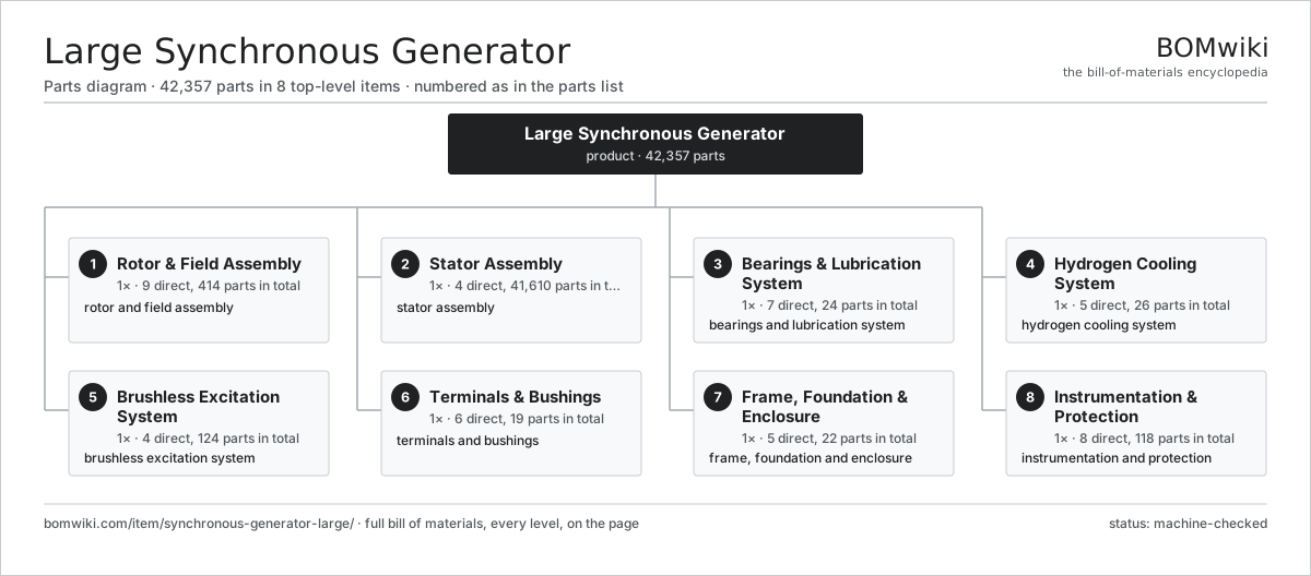
| # | Part | Qty | What it does |
|---|---|---|---|
| 1 | Rotor & Field Assembly 9 parts | 1× | rotor and field assembly |
| 2 | Stator Assembly 4 parts | 1× | stator assembly |
| 3 | Bearings & Lubrication System 7 parts | 1× | bearings and lubrication system |
| 4 | Hydrogen Cooling System 5 parts | 1× | hydrogen cooling system |
| 5 | Brushless Excitation System 4 parts | 1× | brushless excitation system |
| 6 | Terminals & Bushings 6 parts | 1× | terminals and bushings |
| 7 | Frame, Foundation & Enclosure 5 parts | 1× | frame, foundation and enclosure |
| 8 | Instrumentation & Protection 8 parts | 1× | instrumentation and protection |
3D model
No 3D model yet. Have a CAD file of this? Add a 3D model. STL renders right on this page; STEP, FreeCAD, and OpenSCAD sources are welcome too (openly licensed, like all 3D models on BOMwiki).
Build & assembly graph
expand / collapse · shared sub-assemblies converge · links to related products · est. labourTap an assembly to expand/collapse · tap a part to open it · use “Open page” for any node · drag to pan, scroll to zoom.
Bill of materials for Large Synchronous Generator
8 top-level lines · 101 rows shown · 42,357 parts total · indented to 3 levels| # | Item / sub-assembly | Part no. | Qty/assy | Ext. qty | Parts | Type |
|---|---|---|---|---|---|---|
| 1 | Rotor & Field Assembly 9 parts | synchronous-generator-large-rotor | 1× | 1 | 414 | assembly |
| 1.1 | Rotor Body Forging | synchronous-generator-large-rotor-forging | 1× | 1 | · | part |
| 1.2 | Field Winding 3 parts | synchronous-generator-large-field-winding | 1× | 1 | 50 | assembly |
| 1.2.1 | Field Coil | synchronous-generator-large-field-coil | 16× | 16 | · | part |
| 1.2.2 | Field Slot Liner | synchronous-generator-large-slot-liner | 32× | 32 | · | part |
| 1.2.3 | Radial Field Lead | synchronous-generator-large-field-lead | 2× | 2 | · | part |
| 1.3 | Retaining Ring | synchronous-generator-large-retaining-ring | 2× | 2 | · | part |
| 1.4 | Slip Ring | synchronous-generator-large-slip-ring | 2× | 2 | · | part |
| 1.5 | Brushgear Assembly 3 parts | synchronous-generator-large-brushgear | 1× | 1 | 144 | assembly |
| 1.5.1 | Carbon Brush | synchronous-generator-large-carbon-brush | 48× | 48 | · | part |
| 1.5.2 | Brush Holder | synchronous-generator-large-brush-holder | 48× | 48 | · | part |
| 1.5.3 | Coil Spring | coil-spring | 48× | 48 | · | part |
| 1.6 | Rotor Fan | synchronous-generator-large-rotor-fan | 2× | 2 | · | part |
| 1.7 | Field Slot Wedge | synchronous-generator-large-rotor-wedge | 200× | 200 | · | part |
| 1.8 | Balance Weight | synchronous-generator-large-balance-weight | 12× | 12 | · | part |
| 1.9 | Coupling Flange | synchronous-generator-large-coupling | 1× | 1 | · | part |
| 2 | Stator Assembly 4 parts | synchronous-generator-large-stator | 1× | 1 | 41,610 | assembly |
| 2.1 | Laminated Stator Core 3 parts | synchronous-generator-large-core | 1× | 1 | 41,224 | assembly |
| 2.1.1 | Core Lamination | synchronous-generator-large-lamination | 40000× | 40,000 | · | part |
| 2.1.2 | Vent Duct Spacer | synchronous-generator-large-vent-spacer | 1200× | 1,200 | · | part |
| 2.1.3 | Core Through-Bolt | synchronous-generator-large-core-bolt | 24× | 24 | · | part |
| 2.2 | Three-Phase Stator Winding 5 parts | synchronous-generator-large-stator-winding | 1× | 1 | 358 | assembly |
| 2.2.1 | Roebel Bar | synchronous-generator-large-roebel-bar | 84× | 84 | · | part |
| 2.2.2 | Stator Slot Wedge | synchronous-generator-large-slot-wedge | 84× | 84 | · | part |
| 2.2.3 | End-Winding Support 3 parts + deeper › | synchronous-generator-large-end-winding-support | 1× | 1 | 172 | assembly |
| 2.2.4 | Phase Ring Connector | synchronous-generator-large-phase-connector | 6× | 6 | · | part |
| 2.2.5 | Slot RTD | synchronous-generator-large-rtd-strip | 12× | 12 | · | part |
| 2.3 | Stator Frame 3 parts | synchronous-generator-large-stator-frame | 1× | 1 | 26 | assembly |
| 2.3.1 | Sheet Metal Panel | sheet-panel | 8× | 8 | · | part |
| 2.3.2 | Core Spring Bar | synchronous-generator-large-spring-bar | 16× | 16 | · | part |
| 2.3.3 | End Shield | synchronous-generator-large-end-shield | 2× | 2 | · | part |
| 2.4 | Core Clamping Plate | synchronous-generator-large-core-clamp | 2× | 2 | · | part |
| 3 | Bearings & Lubrication System 7 parts | synchronous-generator-large-bearings | 1× | 1 | 24 | assembly |
| 3.1 | Journal Bearing 2 parts | synchronous-generator-large-journal-bearing | 2× | 2 | 6 | assembly |
| 3.1.1 | Tilting Pad | synchronous-generator-large-bearing-pad | 5× | 10 | · | part |
| 3.1.2 | Bearing Shell | synchronous-generator-large-bearing-shell | 1× | 2 | · | part |
| 3.2 | Bearing Insulation | synchronous-generator-large-bearing-insulation | 2× | 2 | · | part |
| 3.3 | Lube Oil Pump | synchronous-generator-large-oil-pump | 2× | 2 | · | part |
| 3.4 | Jacking Oil Pump | synchronous-generator-large-jacking-pump | 1× | 1 | · | part |
| 3.5 | Oil Cooler | synchronous-generator-large-oil-cooler | 2× | 2 | · | part |
| 3.6 | Oil Filter | synchronous-generator-large-oil-filter | 1× | 1 | · | part |
| 3.7 | Oil Seal | oil-seal | 4× | 4 | · | part |
| 4 | Hydrogen Cooling System 5 parts | synchronous-generator-large-cooling | 1× | 1 | 26 | assembly |
| 4.1 | Hydrogen Cooler | synchronous-generator-large-h2-cooler | 4× | 4 | · | part |
| 4.2 | Shaft Hydrogen Seal 2 parts | synchronous-generator-large-shaft-seal | 2× | 2 | 2 | assembly |
| 4.2.1 | Hydrogen Seal Ring | synchronous-generator-large-seal-ring | 1× | 2 | · | part |
| 4.2.2 | O-Ring Set | oring-set | 1× | 2 | · | part |
| 4.3 | Seal Oil Unit 3 parts | synchronous-generator-large-seal-oil-unit | 1× | 1 | 7 | assembly |
| 4.3.1 | Seal Oil Pump | synchronous-generator-large-seal-oil-pump | 2× | 2 | · | part |
| 4.3.2 | Vacuum Tank | synchronous-generator-large-vacuum-tank | 1× | 1 | · | part |
| 4.3.3 | Pressure Sensor | pressure-sensor | 4× | 4 | · | part |
| 4.4 | Gas Control Panel 3 parts | synchronous-generator-large-gas-control | 1× | 1 | 7 | assembly |
| 4.4.1 | Purity Analyser | synchronous-generator-large-purity-analyzer | 1× | 1 | · | part |
| 4.4.2 | Pressure Sensor | pressure-sensor | 2× | 2 | · | part |
| 4.4.3 | Relay | relay | 4× | 4 | · | part |
| 4.5 | Stator Water Cooling Skid 3 parts | synchronous-generator-large-water-skid | 1× | 1 | 4 | assembly |
| 4.5.1 | Cooling Water Pump | synchronous-generator-large-water-pump | 2× | 2 | · | part |
| 4.5.2 | Water Cooler | synchronous-generator-large-water-cooler | 1× | 1 | · | part |
| 4.5.3 | Deioniser | synchronous-generator-large-ion-exchanger | 1× | 1 | · | part |
| 5 | Brushless Excitation System 4 parts | synchronous-generator-large-exciter | 1× | 1 | 124 | assembly |
| 5.1 | AC Exciter 2 parts | synchronous-generator-large-ac-exciter | 1× | 1 | 22 | assembly |
| 5.1.1 | Stator Assembly 3 parts + deeper › | stator-assembly | 1× | 1 | 3 | assembly |
| 5.1.2 | Rotor Assembly 4 parts + deeper › | rotor-assembly | 1× | 1 | 19 | assembly |
| 5.2 | Rotating Rectifier Wheel 2 parts | synchronous-generator-large-rectifier-wheel | 1× | 1 | 72 | assembly |
| 5.2.1 | Rotating Diode | synchronous-generator-large-rotating-diode | 36× | 36 | · | part |
| 5.2.2 | Diode Fuse | synchronous-generator-large-fuse-link | 36× | 36 | · | part |
| 5.3 | Permanent-Magnet Pilot Generator 2 parts | synchronous-generator-large-pmg | 1× | 1 | 22 | assembly |
| 5.3.1 | Stator Assembly 3 parts + deeper › | stator-assembly | 1× | 1 | 3 | assembly |
| 5.3.2 | Rotor Assembly 4 parts + deeper › | rotor-assembly | 1× | 1 | 19 | assembly |
| 5.4 | Automatic Voltage Regulator 4 parts | synchronous-generator-large-avr | 1× | 1 | 8 | assembly |
| 5.4.1 | Bare PCB | pcb-bare | 4× | 4 | · | part |
| 5.4.2 | Microcontroller | mcu | 2× | 2 | · | part |
| 5.4.3 | SMD Passive (R/C/L) | smd-passives | 1× | 1 | · | part |
| 5.4.4 | LCD Panel | lcd-panel | 1× | 1 | · | part |
| 6 | Terminals & Bushings 6 parts | synchronous-generator-large-terminals | 1× | 1 | 19 | assembly |
| 6.1 | Terminal Bushing | synchronous-generator-large-hv-bushing | 6× | 6 | · | part |
| 6.2 | Neutral CT | synchronous-generator-large-neutral-ct | 3× | 3 | · | part |
| 6.3 | Line CT | synchronous-generator-large-line-ct | 3× | 3 | · | part |
| 6.4 | Surge Capacitor | synchronous-generator-large-surge-capacitor | 3× | 3 | · | part |
| 6.5 | Surge Arrester | synchronous-generator-large-surge-arrester | 3× | 3 | · | part |
| 6.6 | Neutral Grounding Transformer | synchronous-generator-large-neutral-transformer | 1× | 1 | · | part |
| 7 | Frame, Foundation & Enclosure 5 parts | synchronous-generator-large-frame | 1× | 1 | 22 | assembly |
| 7.1 | Bearing Pedestal | synchronous-generator-large-bearing-pedestal | 2× | 2 | · | part |
| 7.2 | Sole Plate | synchronous-generator-large-sole-plate | 4× | 4 | · | part |
| 7.3 | Foundation Bolt | synchronous-generator-large-foundation-bolt | 8× | 8 | · | part |
| 7.4 | End Cover | synchronous-generator-large-end-cover | 2× | 2 | · | part |
| 7.5 | Fastener Set | fastener-set | 6× | 6 | · | part |
| 8 | Instrumentation & Protection 8 parts | synchronous-generator-large-instrumentation | 1× | 1 | 118 | assembly |
| 8.1 | Vibration Probe | synchronous-generator-large-vibration-probe | 8× | 8 | · | part |
| 8.2 | Bearing RTD | synchronous-generator-large-bearing-rtd | 8× | 8 | · | part |
| 8.3 | Gas RTD | synchronous-generator-large-gas-rtd | 12× | 12 | · | part |
| 8.4 | PD Coupler | synchronous-generator-large-pd-coupler | 6× | 6 | · | part |
| 8.5 | Air-Gap Flux Probe | synchronous-generator-large-flux-probe | 1× | 1 | · | part |
| 8.6 | Protection Relay 5 parts | synchronous-generator-large-protection-relay | 1× | 1 | 21 | assembly |
| 8.6.1 | Bare PCB | pcb-bare | 5× | 5 | · | part |
| 8.6.2 | Microcontroller | mcu | 2× | 2 | · | part |
| 8.6.3 | Relay | relay | 12× | 12 | · | part |
| 8.6.4 | LCD Panel | lcd-panel | 1× | 1 | · | part |
| 8.6.5 | Power Supply | power-supply | 1× | 1 | · | part |
| 8.7 | Wire Bundle | wire-bundle | 2× | 2 | · | part |
| 8.8 | Connector | connector | 60× | 60 | · | part |
Related products
same domain, ranked by shared parts Combined Heat and Power Unit
522 parts · shares 17 with this page
Combined Heat and Power Unit
522 parts · shares 17 with this page
 Electrostatic Precipitator
879 parts · shares 15 with this page
Electrostatic Precipitator
879 parts · shares 15 with this page
 HVDC Converter Station
18,173 parts · shares 15 with this page
HVDC Converter Station
18,173 parts · shares 15 with this page
 Air-Insulated Substation Bay
1,329 parts · shares 15 with this page
Air-Insulated Substation Bay
1,329 parts · shares 15 with this page
 Coal Pulverizer Mill
313 parts · shares 15 with this page
Coal Pulverizer Mill
313 parts · shares 15 with this page
Sourcing: possible vendors
Browse the supplier directory → Prices, MOQ, and lead times are algorithmic estimates, not quotes, and not claims about these companies. Company mappings are curated by keyword; est. price band $5k–$50M. How estimates work| Vendor | HQ | Specialty | MOQ | Lead time |
|---|---|---|---|---|
| gevernova.com ↗ | Cambridge, US | Power generation | made to order | 20–40 wks |
| siemens-energy.com ↗ | Munich, DE | Power & grid | made to order | 20–40 wks |
| hitachienergy.com ↗ | Zurich, CH | Grid & transformers | made to order | 20–40 wks |
|
🇨🇭ABB
abb.com ↗
|
Zurich, CH | Electrification & automation | made to order | 20–40 wks |
| se.com ↗ | Rueil-Malmaison, FR | Electrical & automation | made to order | 20–40 wks |
1,136-word article