Generator Excitation System
ProductOverview
A generator excitation system supplies and regulates the direct current that flows through the field winding of a synchronous generator. That field current sets up the rotating magnetic flux, which in turn determines the generator terminal voltage and the amount of reactive power the machine exchanges with the grid. Without controlled excitation a synchronous generator cannot hold a stable voltage, cannot share reactive load with other machines, and cannot ride through faults.
This unit is a static excitation system, also called a self-excited or shunt-fed system. It draws its power from the generator terminals themselves through an Excitation Transformer, rectifies that power with a Power Rectifier Bridge, and delivers the result to the rotor field through slip rings and brushes. Because the power path runs through solid-state thyristors with no rotating exciter, the system reacts quickly. Ceiling voltage is reached in under 50 ms, which is what lets the excitation push extra field current into the rotor during a nearby fault to keep the machine in synchronism.
How it works
The generator terminal voltage is measured by the Voltage Transducer and compared against the operator setpoint inside the AVR Regulator Cabinet. The error drives a PID Firmware Module regulator that computes a firing angle. The firing angle tells the Firing and Gate Driver when, within each AC half cycle, to turn on the thyristors. A small firing angle lets the bridge pass more of the AC waveform and raises the DC field voltage; a large firing angle cuts the output back. By moving the firing angle continuously, the regulator holds terminal voltage to within plus or minus 0.25 percent regardless of load.
The loop is fast and self-correcting. If a load is switched on and terminal voltage dips, the regulator reduces the firing angle, the bridge pushes more current into the field, the flux rises, and voltage recovers within a few cycles. Stator current is also measured by the Current Transducer so the regulator can apply a reactive droop and share VAr load fairly with parallel machines.
Power circuit and rectifier
The heart of the power path is the Power Rectifier Bridge, a six-pulse fully-controlled bridge built from six SCR Thyristor Module thyristors. Each device is rated around 1600 V and 1200 A average and is clamped to an Bridge Heatsink by a calibrated Module Clamp Assembly to guarantee even contact pressure and heat transfer. The six modules are arranged as three phase legs, each leg switching the positive and negative half of one input phase.
Every thyristor carries an Snubber Network, an RC branch that limits the rate of voltage rise across the device and damps the ringing that follows commutation. A fast-acting Semiconductor Fuse in each leg clears a shorted device before the silicon junction is destroyed. Field current leaves the bridge through a laminated Bridge Busbar, and a precision DC Current Shunt reads the actual DC current back to the regulator for the inner current loop. Conduction loss in the modules is removed by the Bridge Cooling System system, whose redundant Cooling Fan units and Airflow Switch guard against a loss of ventilation.
AVR and control
The AVR Regulator Cabinet holds two Digital Regulator Board channels in a dual-redundant arrangement. Each board carries an Microcontroller running the regulation loop, an ADC Measurement Front End for isolated measurement, and the supporting SMD Passive (R/C/L) and Connector hardware on a Bare PCB substrate. One channel is in control while the other tracks it, so a fault forces a bumpless transfer with no voltage disturbance. Power for the boards comes from redundant Power Supply units.
The operator works through an HMI Operator Panel with an LCD Panel touch screen for setpoint entry, mode selection between automatic voltage regulation and manual field current control, and event review. An I/O Interface Board handles hard-wired trips and remote setpoints, while the Communication Board links the cabinet to plant SCADA over Modbus TCP and IEC 61850. The Power System Stabilizer adds a power system stabilizer that injects a damping signal into the voltage reference to suppress low-frequency electromechanical oscillations.
Field flashing and de-excitation
A self-excited system has a chicken-and-egg problem at startup: it needs terminal voltage to make field current, but it needs field current to make terminal voltage. The Field Flashing Circuit circuit breaks the deadlock. At startup the Field Flash Contactor connects a Flashing Battery Bank or Flash Rectifier through a Flash Limiting Resistor to the field for a few seconds, building enough residual flux that the main bridge can take over. A Blocking Diode then isolates the flashing source.
Shutting the field down safely matters just as much. The rotor winding stores significant magnetic energy, and simply opening the circuit would produce a destructive voltage spike. The Field Breaker and Crowbar assembly handles this. On a normal stop or a trip the DC Field Breaker opens, its Arc Chute quenches the DC arc, and the stored energy is routed by the Field Discharge Diode into the De-excitation Resistor, which dissipates it as heat. If rotor voltage still rises too far, the Crowbar Thyristor fires to clamp it.
Limiters and protection
The Protection and Limiters block keeps the machine inside its capability curve. The Over-excitation Limiter caps field current on an inverse-time characteristic so the rotor winding is never overheated during sustained overexcitation. The Under-excitation Limiter raises excitation when the machine drifts toward the steady-state stability limit during light or leading load. The Volts-per-Hertz Limiter watches the volts-per-hertz ratio and pulls excitation back at low speed or overvoltage to protect the iron from saturation. A Loss-of-Field Relay trips the unit if the field is lost, preventing the rotor from pole slipping.
Variants and use
Static excitation as built here is the common choice for medium and large synchronous generators in thermal, hydro, and gas turbine plants, and for large synchronous motors and condensers. Where the design must hold excitation during a total terminal short, a separately-excited variant takes its power from an auxiliary bus or a permanent magnet generator rather than the machine terminals. Brushless excitation, by contrast, mounts a rotating exciter and rotating rectifier on the shaft and removes the slip rings entirely, at the cost of slower response. The static system documented here trades that mechanical simplicity for the fast response ratio and high ceiling voltage that grid codes increasingly demand.
Generator Excitation System parts and their functions
9 top-level parts · 937 parts in total · full bill of materials below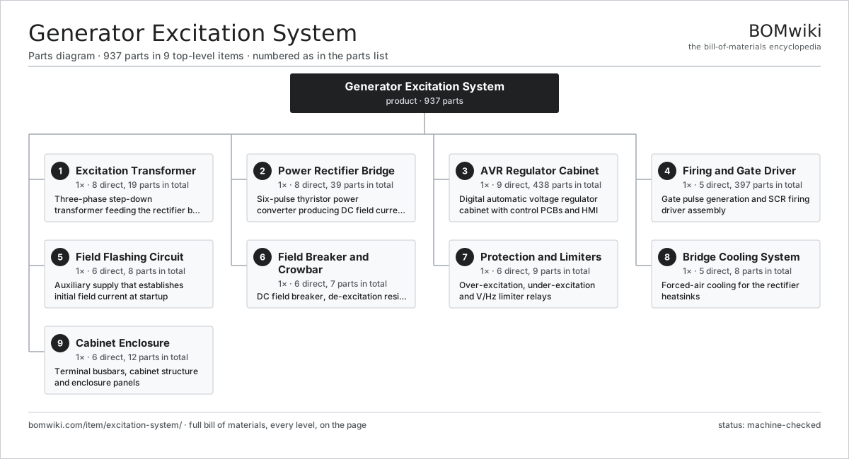
| # | Part | Qty | What it does |
|---|---|---|---|
| 1 | Excitation Transformer 8 parts | 1× | Three-phase step-down transformer feeding the rectifier bridge |
| 2 | Power Rectifier Bridge 8 parts | 1× | Six-pulse thyristor power converter producing DC field current |
| 3 | AVR Regulator Cabinet 9 parts | 1× | Digital automatic voltage regulator cabinet with control PCBs and HMI |
| 4 | Firing and Gate Driver 5 parts | 1× | Gate pulse generation and SCR firing driver assembly |
| 5 | Field Flashing Circuit 6 parts | 1× | Auxiliary supply that establishes initial field current at startup |
| 6 | Field Breaker and Crowbar 6 parts | 1× | DC field breaker, de-excitation resistor and crowbar protection |
| 7 | Protection and Limiters 6 parts | 1× | Over-excitation, under-excitation and V/Hz limiter relays |
| 8 | Bridge Cooling System 5 parts | 1× | Forced-air cooling for the rectifier heatsinks |
| 9 | Cabinet Enclosure 6 parts | 1× | Terminal busbars, cabinet structure and enclosure panels |
3D model
No 3D model yet. Have a CAD file of this? Add a 3D model. STL renders right on this page; STEP, FreeCAD, and OpenSCAD sources are welcome too (openly licensed, like all 3D models on BOMwiki).
Build & assembly graph
expand / collapse · shared sub-assemblies converge · links to related products · est. labourTap an assembly to expand/collapse · tap a part to open it · use “Open page” for any node · drag to pan, scroll to zoom.
Bill of materials for Generator Excitation System
9 top-level lines · 85 rows shown · 937 parts total · indented to 3 levels| # | Item / sub-assembly | Part no. | Qty/assy | Ext. qty | Parts | Type |
|---|---|---|---|---|---|---|
| 1 | Excitation Transformer 8 parts | excitation-system-excitation-transformer | 1× | 1 | 19 | assembly |
| 1.1 | Transformer Core | excitation-system-transformer-core | 1× | 1 | · | part |
| 1.2 | Primary Winding | excitation-system-transformer-primary-winding | 3× | 3 | · | part |
| 1.3 | Secondary Winding | excitation-system-transformer-secondary-winding | 3× | 3 | · | part |
| 1.4 | Off-Load Tap Changer | excitation-system-transformer-tap-changer | 1× | 1 | · | part |
| 1.5 | HV Bushing | excitation-system-transformer-bushing | 6× | 6 | · | part |
| 1.6 | Winding Temperature Sensor | excitation-system-transformer-temp-sensor | 3× | 3 | · | part |
| 1.7 | Core Clamping Frame | excitation-system-transformer-frame | 1× | 1 | · | part |
| 1.8 | Fastener Set | fastener-set | 1× | 1 | · | part |
| 2 | Power Rectifier Bridge 8 parts | excitation-system-rectifier-bridge | 1× | 1 | 39 | assembly |
| 2.1 | SCR Thyristor Module | excitation-system-scr-module | 6× | 6 | · | part |
| 2.2 | Bridge Heatsink | excitation-system-bridge-heatsink | 6× | 6 | · | part |
| 2.3 | Snubber Network 2 parts | excitation-system-snubber-network | 6× | 6 | 2 | assembly |
| 2.3.1 | Snubber Capacitor | excitation-system-snubber-capacitor | 1× | 6 | · | part |
| 2.3.2 | Snubber Resistor | excitation-system-snubber-resistor | 1× | 6 | · | part |
| 2.4 | Semiconductor Fuse | excitation-system-dc-fuse | 6× | 6 | · | part |
| 2.5 | Bridge Busbar | excitation-system-bridge-busbar | 1× | 1 | · | part |
| 2.6 | DC Current Shunt | excitation-system-bridge-current-shunt | 1× | 1 | · | part |
| 2.7 | Module Clamp Assembly | excitation-system-clamp-assembly | 6× | 6 | · | part |
| 2.8 | Fastener Set | fastener-set | 1× | 1 | · | part |
| 3 | AVR Regulator Cabinet 9 parts | excitation-system-avr-cabinet | 1× | 1 | 438 | assembly |
| 3.1 | Digital Regulator Board 5 parts | excitation-system-regulator-board | 2× | 2 | 191 | assembly |
| 3.1.1 | Bare PCB | pcb-bare | 1× | 2 | · | part |
| 3.1.2 | Microcontroller | mcu | 1× | 2 | · | part |
| 3.1.3 | SMD Passive (R/C/L) | smd-passives | 180× | 360 | · | part |
| 3.1.4 | ADC Measurement Front End | excitation-system-adc-frontend | 1× | 2 | · | part |
| 3.1.5 | Connector | connector | 8× | 16 | · | part |
| 3.2 | PID Firmware Module | excitation-system-pid-firmware | 1× | 1 | · | part |
| 3.3 | Voltage Transducer 3 parts | excitation-system-voltage-transducer | 1× | 1 | 42 | assembly |
| 3.3.1 | Bare PCB | pcb-bare | 1× | 1 | · | part |
| 3.3.2 | SMD Passive (R/C/L) | smd-passives | 40× | 40 | · | part |
| 3.3.3 | Sensing Voltage Transformer | excitation-system-sensing-vt | 1× | 1 | · | part |
| 3.4 | Current Transducer | excitation-system-current-transducer | 1× | 1 | · | part |
| 3.5 | Control Power Supply | excitation-system-power-supply | 2× | 2 | · | part |
| 3.6 | HMI Operator Panel 4 parts | excitation-system-hmi-panel | 1× | 1 | 7 | assembly |
| 3.6.1 | LCD Panel | lcd-panel | 1× | 1 | · | part |
| 3.6.2 | Bare PCB | pcb-bare | 1× | 1 | · | part |
| 3.6.3 | Microcontroller | mcu | 1× | 1 | · | part |
| 3.6.4 | Connector | connector | 4× | 4 | · | part |
| 3.7 | I/O Interface Board | excitation-system-io-board | 1× | 1 | · | part |
| 3.8 | Communication Board | excitation-system-comms-board | 1× | 1 | · | part |
| 3.9 | Wire Bundle | wire-bundle | 1× | 1 | · | part |
| 4 | Firing and Gate Driver 5 parts | excitation-system-firing-driver | 1× | 1 | 397 | assembly |
| 4.1 | Gate Driver Board 3 parts | excitation-system-gate-driver-board | 6× | 6 | 62 | assembly |
| 4.1.1 | Bare PCB | pcb-bare | 1× | 6 | · | part |
| 4.1.2 | SMD Passive (R/C/L) | smd-passives | 60× | 360 | · | part |
| 4.1.3 | Gate Pulse Transformer | excitation-system-pulse-transformer | 1× | 6 | · | part |
| 4.2 | Gate Pulse Transformer | excitation-system-pulse-transformer | 6× | 6 | · | part |
| 4.3 | Synchronization Board | excitation-system-sync-board | 1× | 1 | · | part |
| 4.4 | Gate-Cathode Cable | excitation-system-gate-cable | 6× | 6 | · | part |
| 4.5 | Connector | connector | 12× | 12 | · | part |
| 5 | Field Flashing Circuit 6 parts | excitation-system-field-flashing | 1× | 1 | 8 | assembly |
| 5.1 | Field Flash Contactor | excitation-system-flash-contactor | 1× | 1 | · | part |
| 5.2 | Flashing Battery Bank | excitation-system-flash-battery | 1× | 1 | · | part |
| 5.3 | Flash Rectifier | excitation-system-flash-rectifier | 1× | 1 | · | part |
| 5.4 | Flash Limiting Resistor | excitation-system-flash-resistor | 1× | 1 | · | part |
| 5.5 | Blocking Diode | excitation-system-blocking-diode | 2× | 2 | · | part |
| 5.6 | Relay | relay | 2× | 2 | · | part |
| 6 | Field Breaker and Crowbar 6 parts | excitation-system-field-breaker-crowbar | 1× | 1 | 7 | assembly |
| 6.1 | DC Field Breaker | excitation-system-dc-field-breaker | 1× | 1 | · | part |
| 6.2 | De-excitation Resistor | excitation-system-de-excitation-resistor | 1× | 1 | · | part |
| 6.3 | Crowbar Thyristor | excitation-system-crowbar-thyristor | 1× | 1 | · | part |
| 6.4 | Field Discharge Diode | excitation-system-discharge-diode | 1× | 1 | · | part |
| 6.5 | Arc Chute | excitation-system-arc-chute | 1× | 1 | · | part |
| 6.6 | Relay | relay | 2× | 2 | · | part |
| 7 | Protection and Limiters 6 parts | excitation-system-protection-limiters | 1× | 1 | 9 | assembly |
| 7.1 | Over-excitation Limiter | excitation-system-oel-relay | 1× | 1 | · | part |
| 7.2 | Under-excitation Limiter | excitation-system-uel-relay | 1× | 1 | · | part |
| 7.3 | Volts-per-Hertz Limiter | excitation-system-vhz-relay | 1× | 1 | · | part |
| 7.4 | Loss-of-Field Relay | excitation-system-loss-field-relay | 1× | 1 | · | part |
| 7.5 | Power System Stabilizer | excitation-system-pss-module | 1× | 1 | · | part |
| 7.6 | Relay | relay | 4× | 4 | · | part |
| 8 | Bridge Cooling System 5 parts | excitation-system-bridge-cooling | 1× | 1 | 8 | assembly |
| 8.1 | Cooling Fan | excitation-system-cooling-fan | 2× | 2 | · | part |
| 8.2 | Intake Air Filter | excitation-system-air-filter | 2× | 2 | · | part |
| 8.3 | Airflow Switch | excitation-system-airflow-switch | 1× | 1 | · | part |
| 8.4 | Heatsink Thermostat | excitation-system-thermostat | 2× | 2 | · | part |
| 8.5 | Power Supply | power-supply | 1× | 1 | · | part |
| 9 | Cabinet Enclosure 6 parts | excitation-system-enclosure | 1× | 1 | 12 | assembly |
| 9.1 | Sheet Metal Panel | sheet-panel | 6× | 6 | · | part |
| 9.2 | Terminal Busbar Set | excitation-system-terminal-busbar | 1× | 1 | · | part |
| 9.3 | Cabinet Frame | excitation-system-cabinet-frame | 1× | 1 | · | part |
| 9.4 | Gland Plate | excitation-system-gland-plate | 1× | 1 | · | part |
| 9.5 | Door Interlock | excitation-system-door-interlock | 2× | 2 | · | part |
| 9.6 | Fastener Set | fastener-set | 1× | 1 | · | part |
Related products
same domain, ranked by shared parts Combined Heat and Power Unit
522 parts · shares 4 with this page
Containerized Diesel Genset
655 parts · shares 4 with this page
Combined Heat and Power Unit
522 parts · shares 4 with this page
Containerized Diesel Genset
655 parts · shares 4 with this page
 Demand Response Controller
73 parts · shares 4 with this page
Gas Engine Genset
675 parts · shares 4 with this page
Demand Response Controller
73 parts · shares 4 with this page
Gas Engine Genset
675 parts · shares 4 with this page
Sourcing: possible vendors
Browse the supplier directory → Prices, MOQ, and lead times are algorithmic estimates, not quotes, and not claims about these companies. Company mappings are curated by keyword; est. price band $5k–$50M. How estimates work| Vendor | HQ | Specialty | MOQ | Lead time |
|---|---|---|---|---|
| gevernova.com ↗ | Cambridge, US | Power generation | made to order | 20–40 wks |
| siemens-energy.com ↗ | Munich, DE | Power & grid | made to order | 20–40 wks |
| hitachienergy.com ↗ | Zurich, CH | Grid & transformers | made to order | 20–40 wks |
|
🇨🇭ABB
abb.com ↗
|
Zurich, CH | Electrification & automation | made to order | 20–40 wks |
| se.com ↗ | Rueil-Malmaison, FR | Electrical & automation | made to order | 20–40 wks |
1,134-word article