Switchgear Panel
ProductOverview
A switchgear panel controls, protects, and isolates a section of a medium-voltage power network. This metal-clad, draw-out cubicle is rated 12 kV, 1250 A, with a 25 kA short-circuit capacity, and forms one feeder of a substation lineup. "Metal-clad" means each functional part, breaker, busbars, cables, and instruments, sits in its own earthed metal compartment, so a fault in one is contained and the draw-out breaker can be withdrawn safely for maintenance.
Construction
The structure is the Cubicle Enclosure, a sheet-steel metal-clad enclosure partitioned into separate compartments with shutters that automatically cover live contacts when the breaker is withdrawn. Power passes horizontally along the Busbar System, insulated copper busbars and droppers that link this panel to the rest of the lineup.
The switching element is the Vacuum Circuit Breaker, a draw-out vacuum circuit breaker that interrupts current, including fault current, by separating contacts inside a vacuum bottle, where the arc extinguishes at the first current zero. The breaker truck racks in and out on rails for isolation and testing.
Measurement and protection rely on the Instrument Transformers: current transformers and voltage transformers that scale the high primary values down to safe signals. These feed the Numerical Protection Relay, a numerical relay that detects overcurrent, earth fault, and other conditions and trips the breaker within cycles.
Safety and conditioning hardware complete the panel. The Earthing Switch grounds the feeder before maintenance, the Surge Arrester set (one per phase) clamps lightning and switching overvoltages, and the Cable Termination terminates the incoming HV cable on each phase. Control wiring, metering, and the relay sit in the segregated LV Control Compartment compartment.
Switchgear Panel parts and their functions
9 top-level parts · 113 parts in total · full bill of materials below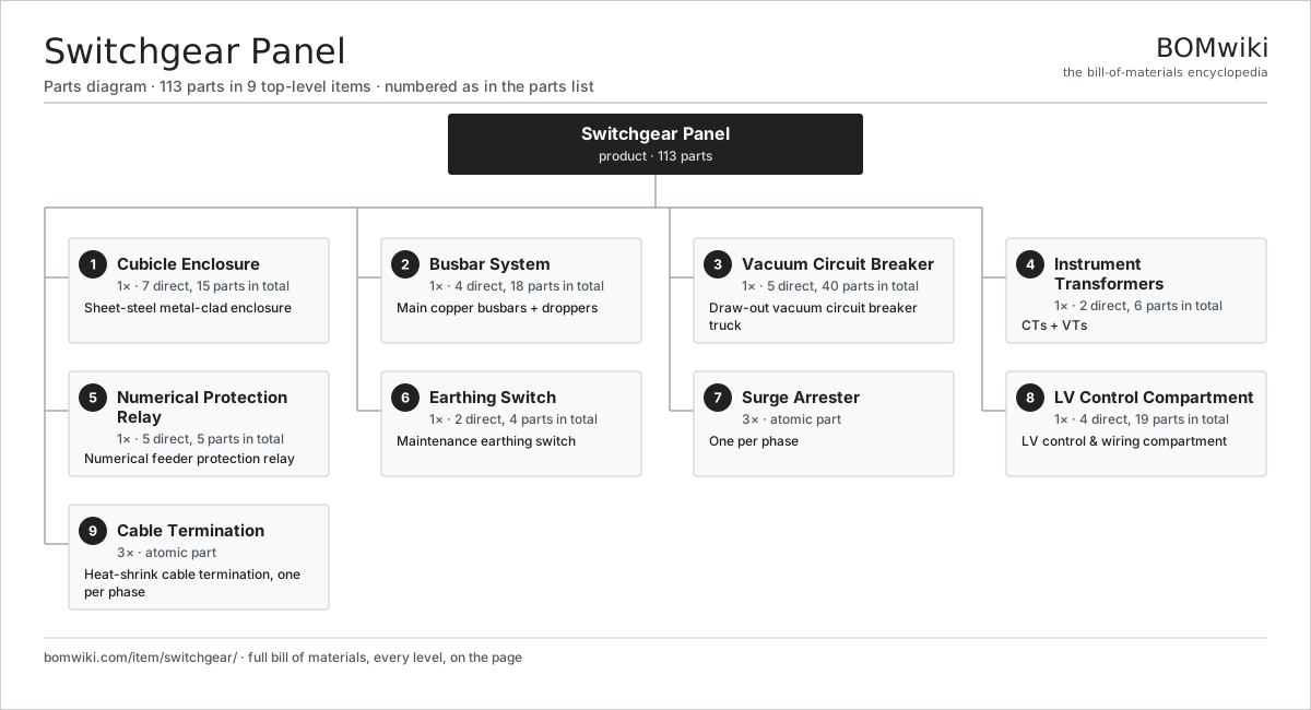
| # | Part | Qty | What it does |
|---|---|---|---|
| 1 | Cubicle Enclosure 7 parts | 1× | Sheet-steel metal-clad enclosure |
| 2 | Busbar System 4 parts | 1× | Main copper busbars + droppers |
| 3 | Vacuum Circuit Breaker 5 parts | 1× | Draw-out vacuum circuit breaker truck |
| 4 | Instrument Transformers 2 parts | 1× | CTs + VTs |
| 5 | Numerical Protection Relay 5 parts | 1× | Numerical feeder protection relay |
| 6 | Earthing Switch 2 parts | 1× | Maintenance earthing switch |
| 7 | Surge Arrester | 3× | One per phase |
| 8 | LV Control Compartment 4 parts | 1× | LV control & wiring compartment |
| 9 | Cable Termination | 3× | Heat-shrink cable termination, one per phase |
3D model
No 3D model yet. Have a CAD file of this? Add a 3D model. STL renders right on this page; STEP, FreeCAD, and OpenSCAD sources are welcome too (openly licensed, like all 3D models on BOMwiki).
Build & assembly graph
expand / collapse · shared sub-assemblies converge · links to related products · est. labourTap an assembly to expand/collapse · tap a part to open it · use “Open page” for any node · drag to pan, scroll to zoom.
Bill of materials for Switchgear Panel
9 top-level lines · 49 rows shown · 113 parts total · indented to 3 levels| # | Item / sub-assembly | Part no. | Qty/assy | Ext. qty | Parts | Type |
|---|---|---|---|---|---|---|
| 1 | Cubicle Enclosure 7 parts | switchgear-cubicle | 1× | 1 | 15 | assembly |
| 1.1 | Sheet-Steel Enclosure Frame | switchgear-enclosure-frame | 1× | 1 | · | part |
| 1.2 | Automatic Shutter Assembly 2 parts | switchgear-shutter-assembly | 1× | 1 | 3 | assembly |
| 1.2.1 | Shutter Plate | switchgear-shutter-plate | 2× | 2 | · | part |
| 1.2.2 | Fastener Set | fastener-set | 1× | 1 | · | part |
| 1.3 | Pressure Relief Flap | switchgear-pressure-relief-flap | 1× | 1 | · | part |
| 1.4 | Anti-Condensation Heater | switchgear-anti-condensation-heater | 1× | 1 | · | part |
| 1.5 | Indication Lamp | switchgear-indication-lamp | 4× | 4 | · | part |
| 1.6 | Panel Meter | switchgear-panel-meter | 1× | 1 | · | part |
| 1.7 | Fastener Set | fastener-set | 4× | 4 | · | part |
| 2 | Busbar System 4 parts | switchgear-busbar-system | 1× | 1 | 18 | assembly |
| 2.1 | Main Copper Busbar | switchgear-main-busbar | 3× | 3 | · | part |
| 2.2 | Busbar Dropper | switchgear-dropper | 3× | 3 | · | part |
| 2.3 | Post Insulator | switchgear-support-insulator | 6× | 6 | · | part |
| 2.4 | Contact Bushing | switchgear-contact-bushing | 6× | 6 | · | part |
| 3 | Vacuum Circuit Breaker 5 parts | switchgear-vcb | 1× | 1 | 40 | assembly |
| 3.1 | Breaker Truck Chassis | switchgear-vcb-truck | 1× | 1 | · | part |
| 3.2 | Embedded Breaker Pole 2 parts | switchgear-vcb-pole | 3× | 3 | 2 | assembly |
| 3.2.1 | Vacuum Interrupter | switchgear-vacuum-interrupter | 1× | 3 | · | part |
| 3.2.2 | Pole Housing | switchgear-pole-housing | 1× | 3 | · | part |
| 3.3 | Spring Operating Mechanism 5 parts | switchgear-operating-mechanism | 1× | 1 | 25 | assembly |
| 3.3.1 | Stator Assembly 3 parts + deeper › | stator-assembly | 1× | 1 | 3 | assembly |
| 3.3.2 | Rotor Assembly 4 parts + deeper › | rotor-assembly | 1× | 1 | 19 | assembly |
| 3.3.3 | Closing Spring | switchgear-closing-spring | 1× | 1 | · | part |
| 3.3.4 | Cam Shaft | switchgear-cam-shaft | 1× | 1 | · | part |
| 3.3.5 | Trip Coil | switchgear-trip-coil | 1× | 1 | · | part |
| 3.4 | Racking Mechanism 2 parts | switchgear-racking-mechanism | 1× | 1 | 2 | assembly |
| 3.4.1 | Racking Lead Screw | switchgear-racking-screw | 1× | 1 | · | part |
| 3.4.2 | Safety Interlock | switchgear-interlock | 1× | 1 | · | part |
| 3.5 | Primary Isolating Contact | switchgear-isolating-contact | 6× | 6 | · | part |
| 4 | Instrument Transformers 2 parts | switchgear-instrument-transformers | 1× | 1 | 6 | assembly |
| 4.1 | Current Transformer | switchgear-current-transformer | 3× | 3 | · | part |
| 4.2 | Voltage Transformer | switchgear-voltage-transformer | 3× | 3 | · | part |
| 5 | Numerical Protection Relay 5 parts | switchgear-protection-relay | 1× | 1 | 5 | assembly |
| 5.1 | Bare PCB | pcb-bare | 1× | 1 | · | part |
| 5.2 | Microcontroller | mcu | 1× | 1 | · | part |
| 5.3 | LCD Panel | lcd-panel | 1× | 1 | · | part |
| 5.4 | CT/VT Input Module | switchgear-relay-input-module | 1× | 1 | · | part |
| 5.5 | Trip Circuit | switchgear-trip-circuit | 1× | 1 | · | part |
| 6 | Earthing Switch 2 parts | switchgear-earthing-switch | 1× | 1 | 4 | assembly |
| 6.1 | Earthing Blade | switchgear-earth-blade | 3× | 3 | · | part |
| 6.2 | Safety Interlock | switchgear-interlock | 1× | 1 | · | part |
| 7 | Surge Arrester | switchgear-surge-arrester | 3× | 3 | · | part |
| 8 | LV Control Compartment 4 parts | switchgear-lv-control | 1× | 1 | 19 | assembly |
| 8.1 | Wire Bundle | wire-bundle | 1× | 1 | · | part |
| 8.2 | Terminal Block | switchgear-terminal-block | 12× | 12 | · | part |
| 8.3 | Relay | relay | 4× | 4 | · | part |
| 8.4 | Connector | connector | 2× | 2 | · | part |
| 9 | Cable Termination | switchgear-cable-termination | 3× | 3 | · | part |
Something wrong in this list? Report a problem with this BOM.
Used in 1 assembly
Related products
same domain, ranked by shared parts Air-Insulated Substation Bay
1,329 parts · shares 11 with this page
Automatic Transfer Switch
212 parts · shares 11 with this page
 Automatic Voltage Regulator
83 parts · shares 11 with this page
Bottom Ash Handling System
1,782 parts · shares 11 with this page
 Coal Pulverizer Mill
313 parts · shares 11 with this page
 Combined Heat and Power Unit
522 parts · shares 11 with this page
Sourcing: possible vendors
Browse the supplier directory → Prices, MOQ, and lead times are algorithmic estimates, not quotes, and not claims about these companies. Company mappings are curated by keyword; est. price band $5k–$50M. How estimates work| Vendor | HQ | Specialty | MOQ | Lead time |
|---|---|---|---|---|
| gevernova.com ↗ | Cambridge, US | Power generation | made to order | 20–40 wks |
| siemens-energy.com ↗ | Munich, DE | Power & grid | made to order | 20–40 wks |
| hitachienergy.com ↗ | Zurich, CH | Grid & transformers | made to order | 20–40 wks |
|
🇨🇭ABB
abb.com ↗
|
Zurich, CH | Electrification & automation | made to order | 20–40 wks |
| se.com ↗ | Rueil-Malmaison, FR | Electrical & automation | made to order | 20–40 wks |
282-word article