Flue Gas Desulfurization Scrubber
ProductOverview
A flue gas desulfurization (FGD) scrubber removes sulfur dioxide from the combustion gas of coal- and oil-fired boilers before it reaches the stack. The dominant design is the wet limestone forced-oxidation absorber, which contacts the flue gas with a fine spray of limestone slurry inside a tall vessel. Sulfur dioxide dissolves into the droplets, reacts with calcium carbonate, and is oxidized to calcium sulfate. The end product is gypsum, the same mineral used to make wallboard, so a well-run plant turns a regulated pollutant into a saleable solid. Removal efficiency runs from 95 to 99 percent, bringing outlet SO2 from inlet values of 500 to 3,000 mg/Nm3 down to 10 to 100 mg/Nm3.
The system handles very large gas volumes. A single absorber on a 600 MW unit treats on the order of 2,000,000 Nm3/h. The major equipment groups are the Absorber Tower Assembly where the reaction happens, the Spray Header and Nozzle System that contacts gas and liquid, the Recycle Slurry Pump Set that move the slurry, the Forced Oxidation Air System that finishes the chemistry, the Limestone Reagent Preparation that makes the limestone slurry, the Mist Eliminator System that cleans up the gas, the Gas Handling System ductwork, and the Gypsum Dewatering System that recovers gypsum.
How it works
Flue gas enters the absorber at 120 to 160 degC through the inlet duct and rises through the spray zone. Recycle pumps lift slurry from the reaction tank to several spray levels, where silicon carbide nozzles atomize it into a dense rain falling counter to the gas. The contact happens at a liquid-to-gas ratio (L/G) of 8 to 20 liters of slurry per cubic meter of gas, which is the main lever for removal efficiency: more spray levels in service raise both removal and pumping power.
The chemistry proceeds in stages. Sulfur dioxide first dissolves into the droplet and forms sulfurous acid, then reacts with dissolved limestone:
SO2 + H2O gives H2SO3, and CaCO3 + H2SO3 gives CaSO3 + CO2 + H2O.
The calcium sulfite is then oxidized in the reaction tank. Blowers in the Forced Oxidation Air System system sparge air through lances near the agitators, supplying 1.5 to 2.5 times the stoichiometric oxygen:
CaSO3 + 1/2 O2 + 2H2O gives CaSO4 dot 2H2O.
Forced oxidation drives the product fully to gypsum rather than a sulfite-sulfate mixture, which dewaters poorly and has no resale value. The reaction tank is held at pH 5.4 to 5.8. Below that the limestone dissolves fast but absorption falls off; above it the limestone is underused and gypsum scaling worsens. A Slurry pH Analyzer trims the reagent feed to hold the band.
Subsystems
The Absorber Tower Assembly is a rubber-lined or alloy-clad steel vessel with an integral lower reaction tank. Side-entry agitators keep gypsum crystals and limestone in suspension so the tank stays a uniform 10 to 15 percent solids. The Recycle Slurry Pump Set are the largest rotating equipment in the system, each a rubber-lined centrifugal pump of 250 to 700 kW; they carry ball-bearing assemblies and an oil-seal at the bearing housing, with a pressure-sensor on each discharge.
The Limestone Reagent Preparation system grinds limestone in a wet ball mill to 90 percent below 44 microns, fine enough to dissolve fast in the short droplet residence time. A hydrocyclone classifier returns coarse particles for regrinding. The Mist Eliminator System uses two stages of polypropylene chevron vanes to strip droplets from the saturated gas, with a wash system that prevents gypsum scale from blinding the vanes. Downstream, the Gypsum Dewatering System system concentrates the bleed slurry in hydrocyclones and dries it on a vacuum belt filter to roughly 50 percent solids, a stackable or saleable cake. The Control and Instrumentation System tie the loops together, with relay outputs to pumps and dampers, a wire-bundle to the field, and an lcd-panel at the local operator station.
Materials
Every wetted surface sees a saturated, chloride-bearing acid, so material selection drives both cost and reliability. The absorber shell is carbon steel protected by a glass-flake vinyl ester or rubber lining, or alternatively clad with nickel alloys such as C-276 in high-chloride service. Spray nozzles are silicon carbide for abrasion resistance. Recycle pump wetted parts are rubber-lined with high-chrome iron impellers. Chevron demister vanes are polypropylene. The wet stack downstream of the absorber needs an acid-resistant liner because the gas leaves the absorber saturated and below its acid dew point.
Variants
Limestone forced-oxidation is the most common design, but several alternatives exist. Magnesium-enhanced lime systems use a more reactive reagent and run smaller absorbers, at higher reagent cost. Seawater scrubbing skips the limestone entirely and uses the natural alkalinity of seawater, suited to coastal plants but producing no saleable byproduct. Spray dryer absorbers and circulating dry scrubbers are dry or semi-dry processes that produce a dry waste and reach lower removal efficiency, used where water is scarce or the unit is small. Among wet absorbers, designs differ by whether they add a Perforated Contact Tray for extra contact and by how many spray levels they carry.
Operation and maintenance
The two operating setpoints that matter most are reaction tank pH and slurry density. A Slurry Density Meter sets the gypsum bleed rate to the dewatering system so the tank inventory stays in range. Inlet and outlet SO2 analyzers report removal efficiency continuously for emissions compliance. The common maintenance items are spray nozzle erosion, recycle pump liner and impeller wear, demister scaling, and lining damage in the absorber. Nozzles and pump liners are designed as replaceable wear parts changed on a planned outage. Gypsum scale on the demister is managed by the wash sequence; if wash water flow drops, the vanes blind, pressure drop climbs, and droplet carryover contaminates the clean gas. Lining inspection through the manways at each outage catches pinholes before the carbon steel beneath is attacked.
Flue Gas Desulfurization Scrubber parts and their functions
9 top-level parts · 531 parts in total · full bill of materials below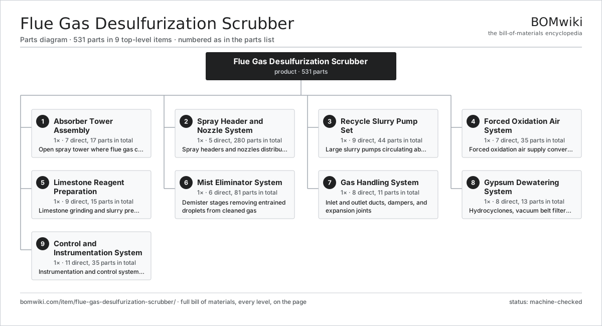
| # | Part | Qty | What it does |
|---|---|---|---|
| 1 | Absorber Tower Assembly 7 parts | 1× | Open spray tower where flue gas contacts limestone slurry |
| 2 | Spray Header and Nozzle System 5 parts | 1× | Spray headers and nozzles distributing recycle slurry across the gas path |
| 3 | Recycle Slurry Pump Set 9 parts | 1× | Large slurry pumps circulating absorbent from the reaction tank to spray levels |
| 4 | Forced Oxidation Air System 7 parts | 1× | Forced oxidation air supply converting sulfite to sulfate |
| 5 | Limestone Reagent Preparation 9 parts | 1× | Limestone grinding and slurry preparation system |
| 6 | Mist Eliminator System 6 parts | 1× | Demister stages removing entrained droplets from cleaned gas |
| 7 | Gas Handling System 8 parts | 1× | Inlet and outlet ducts, dampers, and expansion joints |
| 8 | Gypsum Dewatering System 8 parts | 1× | Hydrocyclones, vacuum belt filter, and gypsum handling |
| 9 | Control and Instrumentation System 11 parts | 1× | Instrumentation and control system for pH, level, and flow |
3D model
No 3D model yet. Have a CAD file of this? Add a 3D model. STL renders right on this page; STEP, FreeCAD, and OpenSCAD sources are welcome too (openly licensed, like all 3D models on BOMwiki).
Build & assembly graph
expand / collapse · shared sub-assemblies converge · links to related products · est. labourTap an assembly to expand/collapse · tap a part to open it · use “Open page” for any node · drag to pan, scroll to zoom.
Bill of materials for Flue Gas Desulfurization Scrubber
9 top-level lines · 79 rows shown · 531 parts total · indented to 3 levels| # | Item / sub-assembly | Part no. | Qty/assy | Ext. qty | Parts | Type |
|---|---|---|---|---|---|---|
| 1 | Absorber Tower Assembly 7 parts | flue-gas-desulfurization-scrubber-absorber-tower | 1× | 1 | 17 | assembly |
| 1.1 | Absorber Tower Shell | flue-gas-desulfurization-scrubber-tower-shell | 1× | 1 | · | part |
| 1.2 | Reaction Tank | flue-gas-desulfurization-scrubber-reaction-tank | 1× | 1 | · | part |
| 1.3 | Side-Entry Agitator | flue-gas-desulfurization-scrubber-side-agitator | 4× | 4 | · | part |
| 1.4 | Perforated Contact Tray | flue-gas-desulfurization-scrubber-perforated-tray | 1× | 1 | · | part |
| 1.5 | Wall Ring | flue-gas-desulfurization-scrubber-wall-rings | 6× | 6 | · | part |
| 1.6 | Glass-Flake Lining | flue-gas-desulfurization-scrubber-flake-lining | 1× | 1 | · | part |
| 1.7 | Inspection Manway | flue-gas-desulfurization-scrubber-manway | 3× | 3 | · | part |
| 2 | Spray Header and Nozzle System 5 parts | flue-gas-desulfurization-scrubber-spray-system | 1× | 1 | 280 | assembly |
| 2.1 | Spray Header Pipe | flue-gas-desulfurization-scrubber-spray-header | 4× | 4 | · | part |
| 2.2 | Slurry Spray Nozzle | flue-gas-desulfurization-scrubber-spray-nozzle | 240× | 240 | · | part |
| 2.3 | Nozzle Branch Lance | flue-gas-desulfurization-scrubber-nozzle-lance | 24× | 24 | · | part |
| 2.4 | Spray Header Support Beam | flue-gas-desulfurization-scrubber-header-support | 8× | 8 | · | part |
| 2.5 | Spray Level Isolation Valve | flue-gas-desulfurization-scrubber-spray-isolation-valve | 4× | 4 | · | part |
| 3 | Recycle Slurry Pump Set 9 parts | flue-gas-desulfurization-scrubber-recycle-pumps | 1× | 1 | 44 | assembly |
| 3.1 | Recycle Pump Casing | flue-gas-desulfurization-scrubber-pump-casing | 4× | 4 | · | part |
| 3.2 | Recycle Pump Impeller | flue-gas-desulfurization-scrubber-pump-impeller | 4× | 4 | · | part |
| 3.3 | Recycle Pump Shaft | flue-gas-desulfurization-scrubber-pump-shaft | 4× | 4 | · | part |
| 3.4 | Recycle Pump Side Liner | flue-gas-desulfurization-scrubber-pump-liner | 8× | 8 | · | part |
| 3.5 | Recycle Pump Motor | flue-gas-desulfurization-scrubber-pump-motor | 4× | 4 | · | part |
| 3.6 | Recycle Pump Mechanical Seal | flue-gas-desulfurization-scrubber-mechanical-seal | 4× | 4 | · | part |
| 3.7 | Ball Bearing | ball-bearing | 8× | 8 | · | part |
| 3.8 | Oil Seal | oil-seal | 4× | 4 | · | part |
| 3.9 | Pressure Sensor | pressure-sensor | 4× | 4 | · | part |
| 4 | Forced Oxidation Air System 7 parts | flue-gas-desulfurization-scrubber-oxidation-air | 1× | 1 | 35 | assembly |
| 4.1 | Oxidation Air Blower | flue-gas-desulfurization-scrubber-oxidation-blower | 2× | 2 | · | part |
| 4.2 | Oxidation Blower Motor | flue-gas-desulfurization-scrubber-blower-motor | 2× | 2 | · | part |
| 4.3 | Oxidation Air Lance | flue-gas-desulfurization-scrubber-air-lance | 12× | 12 | · | part |
| 4.4 | Oxidation Air Header | flue-gas-desulfurization-scrubber-air-header | 1× | 1 | · | part |
| 4.5 | Oxidation Air Check Valve | flue-gas-desulfurization-scrubber-air-check-valve | 12× | 12 | · | part |
| 4.6 | Ball Bearing | ball-bearing | 4× | 4 | · | part |
| 4.7 | Drive Belt | drive-belt | 2× | 2 | · | part |
| 5 | Limestone Reagent Preparation 9 parts | flue-gas-desulfurization-scrubber-reagent-prep | 1× | 1 | 15 | assembly |
| 5.1 | Wet Ball Mill | flue-gas-desulfurization-scrubber-ball-mill | 1× | 1 | · | part |
| 5.2 | Mill Hydrocyclone Classifier | flue-gas-desulfurization-scrubber-mill-classifier | 1× | 1 | · | part |
| 5.3 | Limestone Slurry Tank | flue-gas-desulfurization-scrubber-slurry-tank | 2× | 2 | · | part |
| 5.4 | Slurry Tank Agitator | flue-gas-desulfurization-scrubber-tank-agitator | 2× | 2 | · | part |
| 5.5 | Reagent Feed Pump | flue-gas-desulfurization-scrubber-feed-pump | 2× | 2 | · | part |
| 5.6 | Limestone Weigh Feeder | flue-gas-desulfurization-scrubber-weigh-feeder | 1× | 1 | · | part |
| 5.7 | Ball Bearing | ball-bearing | 4× | 4 | · | part |
| 5.8 | Gearbox Housing | gearbox-housing | 1× | 1 | · | part |
| 5.9 | Helical Gear Pair | gear-pair | 1× | 1 | · | part |
| 6 | Mist Eliminator System 6 parts | flue-gas-desulfurization-scrubber-mist-eliminator | 1× | 1 | 81 | assembly |
| 6.1 | Chevron Vane Module | flue-gas-desulfurization-scrubber-chevron-module | 12× | 12 | · | part |
| 6.2 | Demister Support Frame | flue-gas-desulfurization-scrubber-demister-frame | 2× | 2 | · | part |
| 6.3 | Demister Wash Header | flue-gas-desulfurization-scrubber-wash-header | 2× | 2 | · | part |
| 6.4 | Demister Wash Nozzle | flue-gas-desulfurization-scrubber-wash-nozzle | 60× | 60 | · | part |
| 6.5 | Demister Wash Pump | flue-gas-desulfurization-scrubber-wash-pump | 1× | 1 | · | part |
| 6.6 | Demister Wash Sequencing Valve | flue-gas-desulfurization-scrubber-wash-valve | 4× | 4 | · | part |
| 7 | Gas Handling System 8 parts | flue-gas-desulfurization-scrubber-gas-handling | 1× | 1 | 11 | assembly |
| 7.1 | Flue Gas Inlet Duct | flue-gas-desulfurization-scrubber-inlet-duct | 1× | 1 | · | part |
| 7.2 | Clean Gas Outlet Duct | flue-gas-desulfurization-scrubber-outlet-duct | 1× | 1 | · | part |
| 7.3 | Inlet Isolation Damper | flue-gas-desulfurization-scrubber-inlet-damper | 1× | 1 | · | part |
| 7.4 | Outlet Isolation Damper | flue-gas-desulfurization-scrubber-outlet-damper | 1× | 1 | · | part |
| 7.5 | Fabric Expansion Joint | flue-gas-desulfurization-scrubber-expansion-joint | 4× | 4 | · | part |
| 7.6 | Wet Stack Liner | flue-gas-desulfurization-scrubber-wet-stack-liner | 1× | 1 | · | part |
| 7.7 | Induced Draft Booster Fan | flue-gas-desulfurization-scrubber-booster-fan | 1× | 1 | · | part |
| 7.8 | Booster Fan Motor | flue-gas-desulfurization-scrubber-fan-motor | 1× | 1 | · | part |
| 8 | Gypsum Dewatering System 8 parts | flue-gas-desulfurization-scrubber-dewatering | 1× | 1 | 13 | assembly |
| 8.1 | Gypsum Bleed Pump | flue-gas-desulfurization-scrubber-bleed-pump | 2× | 2 | · | part |
| 8.2 | Primary Hydrocyclone Bank | flue-gas-desulfurization-scrubber-primary-hydrocyclone | 1× | 1 | · | part |
| 8.3 | Vacuum Belt Filter | flue-gas-desulfurization-scrubber-vacuum-belt-filter | 1× | 1 | · | part |
| 8.4 | Filter Vacuum Pump | flue-gas-desulfurization-scrubber-vacuum-pump | 1× | 1 | · | part |
| 8.5 | Filtrate Return Tank | flue-gas-desulfurization-scrubber-filtrate-tank | 1× | 1 | · | part |
| 8.6 | Gypsum Cake Conveyor | flue-gas-desulfurization-scrubber-cake-conveyor | 1× | 1 | · | part |
| 8.7 | Ball Bearing | ball-bearing | 4× | 4 | · | part |
| 8.8 | Oil Seal | oil-seal | 2× | 2 | · | part |
| 9 | Control and Instrumentation System 11 parts | flue-gas-desulfurization-scrubber-controls | 1× | 1 | 35 | assembly |
| 9.1 | Absorber Control PLC | flue-gas-desulfurization-scrubber-plc | 1× | 1 | · | part |
| 9.2 | Slurry pH Analyzer | flue-gas-desulfurization-scrubber-ph-analyzer | 2× | 2 | · | part |
| 9.3 | Slurry Density Meter | flue-gas-desulfurization-scrubber-density-meter | 1× | 1 | · | part |
| 9.4 | SO2 Analyzer | flue-gas-desulfurization-scrubber-so2-analyzer | 2× | 2 | · | part |
| 9.5 | Slurry Level Transmitter | flue-gas-desulfurization-scrubber-level-transmitter | 2× | 2 | · | part |
| 9.6 | Pressure Sensor | pressure-sensor | 3× | 3 | · | part |
| 9.7 | Relay | relay | 8× | 8 | · | part |
| 9.8 | Wire Bundle | wire-bundle | 1× | 1 | · | part |
| 9.9 | Connector | connector | 12× | 12 | · | part |
| 9.10 | LCD Panel | lcd-panel | 1× | 1 | · | part |
| 9.11 | Power Supply | power-supply | 2× | 2 | · | part |
Related products
same domain, ranked by shared parts Coal Pulverizer Mill
313 parts · shares 8 with this page
Coal Pulverizer Mill
313 parts · shares 8 with this page
 Combined Heat and Power Unit
522 parts · shares 8 with this page
Combined Heat and Power Unit
522 parts · shares 8 with this page
 Industrial Gas Turbine Package
2,053 parts · shares 8 with this page
Industrial Gas Turbine Package
2,053 parts · shares 8 with this page
Sourcing: possible vendors
Browse the supplier directory → Prices, MOQ, and lead times are algorithmic estimates, not quotes, and not claims about these companies. Company mappings are curated by keyword; est. price band $5k–$50M. How estimates work| Vendor | HQ | Specialty | MOQ | Lead time |
|---|---|---|---|---|
| gevernova.com ↗ | Cambridge, US | Power generation | made to order | 20–40 wks |
| siemens-energy.com ↗ | Munich, DE | Power & grid | made to order | 20–40 wks |
| hitachienergy.com ↗ | Zurich, CH | Grid & transformers | made to order | 20–40 wks |
|
🇨🇭ABB
abb.com ↗
|
Zurich, CH | Electrification & automation | made to order | 20–40 wks |
| se.com ↗ | Rueil-Malmaison, FR | Electrical & automation | made to order | 20–40 wks |
1,048-word article