Generator Step-Up Transformer
ProductOverview
A Generator Step-Up Transformer, usually abbreviated GSU, sits between a power-plant generator and the transmission grid. Large generators produce power at a relatively low terminal voltage, commonly 11 to 27 kV, because insulating a rotating machine for higher voltage is impractical. The GSU raises that to transmission level, 220 kV, 400 kV or higher, so the plant can deliver its full output across long lines without crippling resistive loss. It is the single transformer that the entire station's production must pass through, which shapes nearly every design choice.
Unlike a substation Power Transformer that sees a varying mix of load, a GSU runs close to its rated power whenever the unit is generating. It is sized for near-continuous full load, with cooling, losses and insulation life all judged against that duty. A GSU also faces the steepest fault currents in the station, since a short on the HV side is fed by the generator behind it, so its windings are braced hard against short-circuit forces.
Magnetic core
The Magnetic Core is stacked from high-permeability grain-oriented laminations, often the thinnest grades available (0.23 mm, laser-scribed) because no-load loss runs continuously for the life of the unit and every watt of core loss is paid for around the clock. The limbs carry the windings and the yokes close the magnetic loop. Clamping frames and tie rods hold the stack tight against magnetostrictive vibration, and the core is earthed once through the earthing strap. Because of the high power density, magnetic flux shunts are fitted to divert stray flux from the tank wall so it does not heat the steel locally.
Windings
The low-voltage generator winding handles enormous current, often well above 10 kA per phase at 20 kV, so it is wound from continuously-transposed conductor to keep eddy and circulating losses down, and its cooling ducts are generous. Outside it sits the high-voltage transmission winding, an interleaved-disc coil of paper-covered copper with reinforced end insulation and static rings to withstand the steep impulse fronts that arrive from the line.
Ratio adjustment uses an off-circuit tap changer rather than an on-load one. A GSU normally exports at a fixed ratio set by the grid code, and the small seasonal correction it needs can be made with the unit de-energised. The tap section in the HV winding is switched by the DETC selector, operated through an external handwheel. Removing the on-load mechanism removes a maintenance item and a failure mode, which suits an asset that must stay available whenever the plant runs.
Insulation and dielectric
The dielectric is an oil-paper system. Kraft paper insulates the conductors, barrier cylinders split the oil gaps, and pressboard spacers set the cooling ducts and carry clamping load. Angle rings and end blocks grade the field at edges so the design holds its 1425 kV BIL. The mineral oil insulates and cools at once, with roughly 90,000 litres in a 500 MVA unit.
Tank and cooling
Because losses are large and constant, the cooling system is forced from the start. The active part hangs in a welded tank, and heat goes out through panel radiators helped by fans. At full output, directed-oil pumps push oil through the winding ducts in an ODAF (oil directed, air forced) scheme so the hot-spot stays within the insulation's thermal limit. Directing the oil rather than just circulating it keeps the winding hot-spot rise controlled even at constant peak load.
Bushings, preservation and protection
Current crosses the tank wall through bushings. The HV side uses condenser bushings graded for transmission voltage, while the LV bushing is a high-current type connecting to the isolated-phase generator bus. Bushing CTs feed the unit's differential protection.
Oil volume change with temperature is taken up by the conservator, sealed from air by an air-cell and kept dry by a silica-gel breather. Internal faults are caught by the Buchholz relay, the sudden-pressure relay and the pressure-relief devices, while the winding temperature indicator and oil temperature indicator manage cooling and tripping. An online dissolved-gas monitor watches for incipient faults, and everything terminates in the marshalling cabinet.
Standards and application
GSU transformers are built and tested to IEC 60076 and the application guidance of IEEE C57.116. They are step-up assets for thermal, hydro, nuclear and large renewable plants, and because a failure can take the whole generating unit offline, many stations carry a spare or an interchangeable design. The complete unit is matched to the generator's terminal voltage, fault contribution and step-up ratio rather than to a varying load, which is the main difference from a general transmission transformer.
Generator Step-Up Transformer parts and their functions
9 top-level parts · 8,676 parts in total · full bill of materials below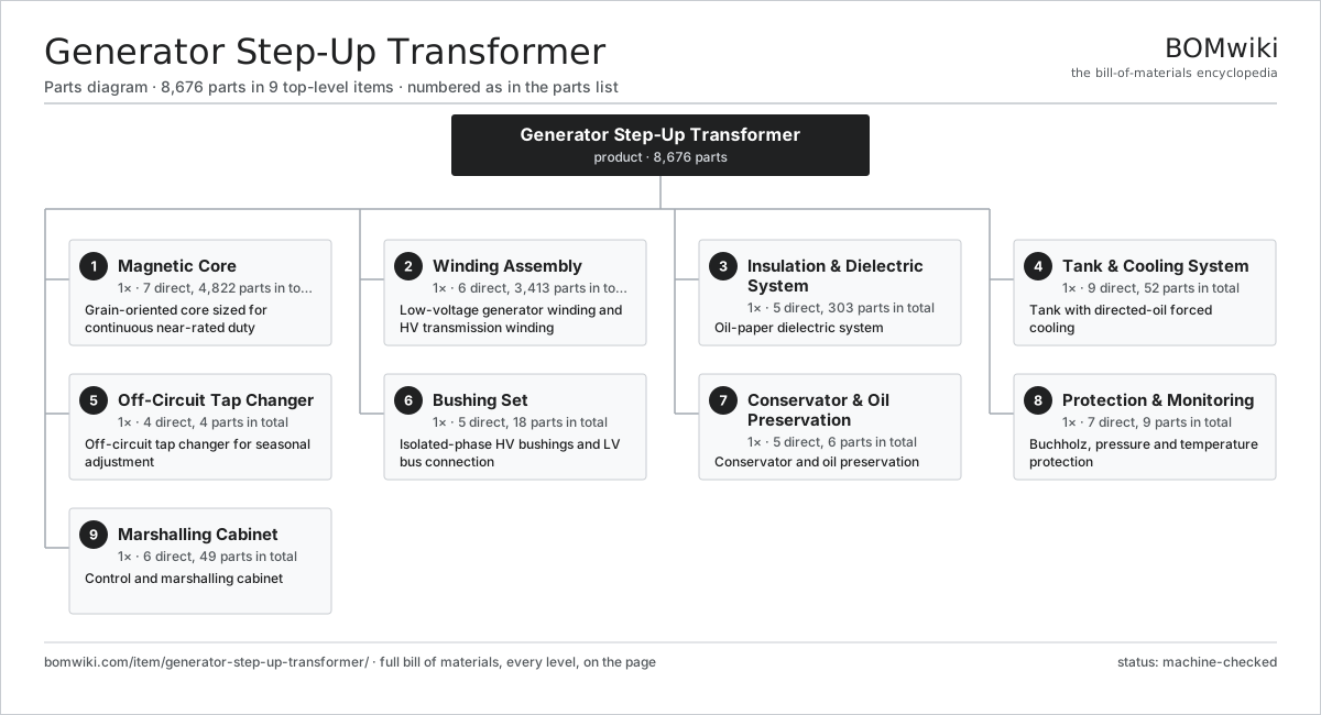
| # | Part | Qty | What it does |
|---|---|---|---|
| 1 | Magnetic Core 7 parts | 1× | Grain-oriented core sized for continuous near-rated duty |
| 2 | Winding Assembly 6 parts | 1× | Low-voltage generator winding and HV transmission winding |
| 3 | Insulation & Dielectric System 5 parts | 1× | Oil-paper dielectric system |
| 4 | Tank & Cooling System 9 parts | 1× | Tank with directed-oil forced cooling |
| 5 | Off-Circuit Tap Changer 4 parts | 1× | Off-circuit tap changer for seasonal adjustment |
| 6 | Bushing Set 5 parts | 1× | Isolated-phase HV bushings and LV bus connection |
| 7 | Conservator & Oil Preservation 5 parts | 1× | Conservator and oil preservation |
| 8 | Protection & Monitoring 7 parts | 1× | Buchholz, pressure and temperature protection |
| 9 | Marshalling Cabinet 6 parts | 1× | Control and marshalling cabinet |
3D model
No 3D model yet. Have a CAD file of this? Add a 3D model. STL renders right on this page; STEP, FreeCAD, and OpenSCAD sources are welcome too (openly licensed, like all 3D models on BOMwiki).
Build & assembly graph
expand / collapse · shared sub-assemblies converge · links to related products · est. labourTap an assembly to expand/collapse · tap a part to open it · use “Open page” for any node · drag to pan, scroll to zoom.
Bill of materials for Generator Step-Up Transformer
9 top-level lines · 70 rows shown · 8,676 parts total · indented to 3 levels| # | Item / sub-assembly | Part no. | Qty/assy | Ext. qty | Parts | Type |
|---|---|---|---|---|---|---|
| 1 | Magnetic Core 7 parts | generator-step-up-transformer-core | 1× | 1 | 4,822 | assembly |
| 1.1 | GO Silicon-Steel Lamination | generator-step-up-transformer-core-lamination | 4800× | 4,800 | · | part |
| 1.2 | Core Limb | generator-step-up-transformer-core-limb | 3× | 3 | · | part |
| 1.3 | Core Yoke | generator-step-up-transformer-core-yoke | 2× | 2 | · | part |
| 1.4 | Core Clamping Frame | generator-step-up-transformer-clamping-frame | 2× | 2 | · | part |
| 1.5 | Core Tie Rod | generator-step-up-transformer-core-tie-rod | 8× | 8 | · | part |
| 1.6 | Core Earthing Strap | generator-step-up-transformer-core-ground-strap | 1× | 1 | · | part |
| 1.7 | Magnetic Flux Shunt | generator-step-up-transformer-flux-shunt | 6× | 6 | · | part |
| 2 | Winding Assembly 6 parts | generator-step-up-transformer-windings | 1× | 1 | 3,413 | assembly |
| 2.1 | LV Generator Winding 3 parts | generator-step-up-transformer-lv-winding | 3× | 3 | 202 | assembly |
| 2.1.1 | Transposed Copper Conductor | generator-step-up-transformer-ctc-conductor | 1× | 3 | · | part |
| 2.1.2 | Kraft Paper Insulation | generator-step-up-transformer-paper-insulation | 1× | 3 | · | part |
| 2.1.3 | Pressboard Spacer | generator-step-up-transformer-pressboard-spacer | 200× | 600 | · | part |
| 2.2 | HV Transmission Winding 4 parts | generator-step-up-transformer-hv-winding | 3× | 3 | 264 | assembly |
| 2.2.1 | Paper-Covered Copper Conductor | generator-step-up-transformer-copper-conductor | 1× | 3 | · | part |
| 2.2.2 | Kraft Paper Insulation | generator-step-up-transformer-paper-insulation | 1× | 3 | · | part |
| 2.2.3 | Electrostatic Static Ring | generator-step-up-transformer-static-ring | 2× | 6 | · | part |
| 2.2.4 | Pressboard Spacer | generator-step-up-transformer-pressboard-spacer | 260× | 780 | · | part |
| 2.3 | Off-Circuit Tap Section | generator-step-up-transformer-tap-section | 3× | 3 | · | part |
| 2.4 | Pressboard Spacer | generator-step-up-transformer-pressboard-spacer | 2000× | 2,000 | · | part |
| 2.5 | Barrier Cylinder | generator-step-up-transformer-barrier-cylinder | 6× | 6 | · | part |
| 2.6 | Winding Clamping Ring | generator-step-up-transformer-clamping-ring | 6× | 6 | · | part |
| 3 | Insulation & Dielectric System 5 parts | generator-step-up-transformer-insulation | 1× | 1 | 303 | assembly |
| 3.1 | Mineral Insulating Oil | generator-step-up-transformer-mineral-oil | 1× | 1 | · | part |
| 3.2 | Pressboard Angle Ring | generator-step-up-transformer-angle-ring | 70× | 70 | · | part |
| 3.3 | Lead Snout | generator-step-up-transformer-snout | 6× | 6 | · | part |
| 3.4 | Oil Duct Stick | generator-step-up-transformer-duct-stick | 220× | 220 | · | part |
| 3.5 | End Insulation Block | generator-step-up-transformer-end-block | 6× | 6 | · | part |
| 4 | Tank & Cooling System 9 parts | generator-step-up-transformer-tank-cooling | 1× | 1 | 52 | assembly |
| 4.1 | Main Tank | generator-step-up-transformer-main-tank | 1× | 1 | · | part |
| 4.2 | Tank Cover | generator-step-up-transformer-tank-cover | 1× | 1 | · | part |
| 4.3 | Panel Radiator | generator-step-up-transformer-radiator | 14× | 14 | · | part |
| 4.4 | Radiator Cooling Fan | generator-step-up-transformer-cooling-fan | 20× | 20 | · | part |
| 4.5 | Directed-Oil Pump | generator-step-up-transformer-oil-pump | 3× | 3 | · | part |
| 4.6 | Tank Valve | generator-step-up-transformer-tank-valve | 8× | 8 | · | part |
| 4.7 | Oil Flow Indicator | flow-indicator-gsu | 3× | 3 | · | part |
| 4.8 | Fastener Set | fastener-set | 1× | 1 | · | part |
| 4.9 | O-Ring Set | oring-set | 1× | 1 | · | part |
| 5 | Off-Circuit Tap Changer 4 parts | generator-step-up-transformer-detc | 1× | 1 | 4 | assembly |
| 5.1 | DETC Selector Contacts | generator-step-up-transformer-detc-selector | 1× | 1 | · | part |
| 5.2 | DETC Operating Shaft | generator-step-up-transformer-detc-shaft | 1× | 1 | · | part |
| 5.3 | DETC Handwheel | generator-step-up-transformer-detc-handwheel | 1× | 1 | · | part |
| 5.4 | DETC Position Plate | generator-step-up-transformer-detc-position-plate | 1× | 1 | · | part |
| 6 | Bushing Set 5 parts | generator-step-up-transformer-bushings | 1× | 1 | 18 | assembly |
| 6.1 | HV Condenser Bushing | generator-step-up-transformer-hv-bushing | 3× | 3 | · | part |
| 6.2 | LV Bushing | generator-step-up-transformer-lv-bushing | 3× | 3 | · | part |
| 6.3 | Neutral Bushing | generator-step-up-transformer-neutral-bushing | 1× | 1 | · | part |
| 6.4 | Bushing Current Transformer | generator-step-up-transformer-bushing-ct | 7× | 7 | · | part |
| 6.5 | Bushing Turret | generator-step-up-transformer-bushing-turret | 4× | 4 | · | part |
| 7 | Conservator & Oil Preservation 5 parts | generator-step-up-transformer-conservator | 1× | 1 | 6 | assembly |
| 7.1 | Conservator Tank | generator-step-up-transformer-conservator-tank | 1× | 1 | · | part |
| 7.2 | Conservator Air-Cell | generator-step-up-transformer-air-cell | 1× | 1 | · | part |
| 7.3 | Silica-Gel Breather | generator-step-up-transformer-breather | 1× | 1 | · | part |
| 7.4 | Magnetic Oil Level Gauge | generator-step-up-transformer-oil-gauge | 1× | 1 | · | part |
| 7.5 | Conservator Valve | generator-step-up-transformer-conservator-valve | 2× | 2 | · | part |
| 8 | Protection & Monitoring 7 parts | generator-step-up-transformer-protection | 1× | 1 | 9 | assembly |
| 8.1 | Buchholz Relay | generator-step-up-transformer-buchholz-relay | 1× | 1 | · | part |
| 8.2 | Pressure Relief Device | generator-step-up-transformer-pressure-relief | 2× | 2 | · | part |
| 8.3 | Sudden-Pressure Relay | generator-step-up-transformer-sudden-pressure-relay | 1× | 1 | · | part |
| 8.4 | Winding Temperature Indicator | generator-step-up-transformer-wti | 1× | 1 | · | part |
| 8.5 | Oil Temperature Indicator | generator-step-up-transformer-oti | 1× | 1 | · | part |
| 8.6 | Pressure Sensor | pressure-sensor | 2× | 2 | · | part |
| 8.7 | Dissolved-Gas Monitor | generator-step-up-transformer-dga-monitor | 1× | 1 | · | part |
| 9 | Marshalling Cabinet 6 parts | generator-step-up-transformer-marshalling-cabinet | 1× | 1 | 49 | assembly |
| 9.1 | Sheet Metal Panel | sheet-panel | 6× | 6 | · | part |
| 9.2 | Cooler Control Unit | generator-step-up-transformer-cooler-control | 1× | 1 | · | part |
| 9.3 | Relay | relay | 8× | 8 | · | part |
| 9.4 | Marshalling Terminal Block | generator-step-up-transformer-terminal-block | 32× | 32 | · | part |
| 9.5 | Wire Bundle | wire-bundle | 1× | 1 | · | part |
| 9.6 | Cabinet Anti-Condensation Heater | generator-step-up-transformer-cabinet-heater | 1× | 1 | · | part |
Related products
same domain, ranked by shared parts Autotransformer
7,784 parts · shares 4 with this page
Bottom Ash Handling System
1,782 parts · shares 4 with this page
Autotransformer
7,784 parts · shares 4 with this page
Bottom Ash Handling System
1,782 parts · shares 4 with this page
 Combined Heat and Power Unit
522 parts · shares 4 with this page
Containerized Diesel Genset
655 parts · shares 4 with this page
Combined Heat and Power Unit
522 parts · shares 4 with this page
Containerized Diesel Genset
655 parts · shares 4 with this page
 Distribution Ring Main Unit
443 parts · shares 4 with this page
Distribution Ring Main Unit
443 parts · shares 4 with this page
 Fuel Dispenser
71 parts · shares 4 with this page
Fuel Dispenser
71 parts · shares 4 with this page
Sourcing: possible vendors
Browse the supplier directory → Prices, MOQ, and lead times are algorithmic estimates, not quotes, and not claims about these companies. Company mappings are curated by keyword; est. price band $5k–$50M. How estimates work| Vendor | HQ | Specialty | MOQ | Lead time |
|---|---|---|---|---|
| gevernova.com ↗ | Cambridge, US | Power generation | made to order | 20–40 wks |
| siemens-energy.com ↗ | Munich, DE | Power & grid | made to order | 20–40 wks |
| hitachienergy.com ↗ | Zurich, CH | Grid & transformers | made to order | 20–40 wks |
|
🇨🇭ABB
abb.com ↗
|
Zurich, CH | Electrification & automation | made to order | 20–40 wks |
| se.com ↗ | Rueil-Malmaison, FR | Electrical & automation | made to order | 20–40 wks |
1,049-word article