HVDC Thyristor Valve
ProductOverview
An HVDC thyristor valve is the controllable switch that converts current between alternating and direct form inside an HVDC converter. The word valve is borrowed from the old mercury-arc rectifiers it replaced: like a check valve for current, it conducts when commanded and blocks when not. A single power semiconductor cannot withstand the hundreds of kilovolts present on an HVDC pole, so the valve is built as a tall series stack of dozens of thyristor levels, each carrying a slice of the total voltage, fired in unison so they switch as one. Six such valves make up a 12-pulse converter bridge.
The valve combines several systems on a valve structure: the series thyristor levels, a water cooling circuit, a valve control unit, a grading network that keeps the levels balanced, and a valve arrester bank for protection.
The Thyristor Level
The repeating building block is the thyristor level, and the valve is essentially this unit copied many times in series. At its core is the power thyristor, a press-pack device the size of a hockey puck. Inside its ceramic housing, a large silicon wafer is sandwiched between molybdenum discs that match the silicon's thermal expansion, and pressed against copper pole pieces that carry current in and heat out. The press-pack construction matters for reliability: when a thyristor fails it shorts rather than opening, so the rest of the series stack keeps working until the next maintenance window, which is why a valve includes a few redundant levels from the start.
Each device is clamped between two water-cooled heat sinks by a spring-loaded press-pack clamp that applies a precise force, too little and the contact resistance rises, too much and the wafer cracks. Around the device sit a snubber capacitor and damping resistor that limit how fast voltage can rise across the thyristor and tame the recovery transient when it turns off, plus a grading resistor for steady-state voltage sharing.
Firing Over Light
Each level floats at a different and very high potential, so the firing command cannot be a simple wire. Instead the gate unit at every level receives its command as a pulse of light down a glass fiber to its fiber receiver, and reports the thyristor's state back up a second fiber through a fiber transmitter. This optical link gives complete electrical isolation between the ground-potential control room and the levels living at hundreds of kilovolts. The gate unit is self-powered, harvesting energy from the valve voltage to charge its gate pulse capacitor so it can deliver a hard, fast firing pulse the instant the light arrives.
Voltage Sharing
For the series stack to work, every level must hold close to the same voltage; if one level took more than its share it would break down and cascade the failure up the valve. The grading network enforces this. A DC grading resistor across each level handles slow, steady-state sharing by bleeding a small balancing current, while an AC grading capacitor handles the fast transient during switching, when stray capacitances would otherwise unbalance the stack in microseconds. Together they keep the voltage distribution uniform from the bottom level to the top.
Cooling
Even at well under one percent loss, a valve passing thousands of amps dissipates a large amount of heat, and the water cooling circuit must remove it without giving the high voltage a path to short out. It circulates deionized water of very low conductivity through a manifold and individual cooling hoses of PVDF plastic to each heat sink. The length and routing of these hoses is engineered so the small leakage current the slightly conductive water still carries is controlled by water electrodes rather than allowed to flow uncontrolled. Leak sensors watch for any coolant escaping inside the valve, which would be both an electrical and a fire hazard.
Control and Protection
The valve control unit sits at ground potential beside the valve and is the interface between the converter's main control and the individual levels. Redundant firing boards compute the exact firing instant, and an optical fiber interface fans the firing and status fibers out to every level. A monitoring board continuously polls each level so operators know how many redundant levels remain and can schedule replacement before the margin runs out.
The valve's last line of defense is the valve arrester bank. A metal-oxide arrester of stacked zinc-oxide blocks is connected directly across the valve, and the moment the voltage tries to exceed the combined blocking capability of the series levels it conducts, clamping the voltage and absorbing the surge energy so no thyristor is overstressed. An arrester duty monitor logs how much energy the arresters have absorbed over their life.
Variants and Use
The thyristor valve described here is the line-commutated type, which switches once per AC cycle and is used in the highest-power, highest-voltage bulk transmission links. The other major family is the voltage-source converter valve, built from IGBT submodules that can be switched on and off freely, used where independent reactive control or black-start capability is needed, such as offshore wind connections. Both are suspended from the valve hall ceiling on composite insulators so the structure rides out earthquakes without straining the levels. The thyristor valve remains the workhorse of long-distance HVDC because press-pack thyristors are rugged, fail safely into a short, and have decades of proven service moving gigawatts across continents.
HVDC Thyristor Valve parts and their functions
6 top-level parts · 6,125 parts in total · full bill of materials below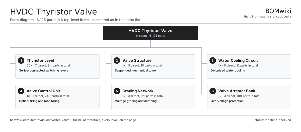
| # | Part | Qty | What it does |
|---|---|---|---|
| 1 | Thyristor Level 7 parts | 60× | Series-connected switching levels |
| 2 | Valve Structure 5 parts | 1× | Suspended mechanical tower |
| 3 | Water Cooling Circuit 5 parts | 1× | Deionized water cooling |
| 4 | Valve Control Unit 5 parts | 1× | Optical firing and monitoring |
| 5 | Grading Network 3 parts | 1× | Voltage grading and damping |
| 6 | Valve Arrester Bank 3 parts | 1× | Overvoltage protection |
3D model
No 3D model yet. Have a CAD file of this? Add a 3D model. STL renders right on this page; STEP, FreeCAD, and OpenSCAD sources are welcome too (openly licensed, like all 3D models on BOMwiki).
Build & assembly graph
expand / collapse · shared sub-assemblies converge · links to related products · est. labourTap an assembly to expand/collapse · tap a part to open it · use “Open page” for any node · drag to pan, scroll to zoom.
Bill of materials for HVDC Thyristor Valve
6 top-level lines · 60 rows shown · 6,125 parts total · indented to 3 levels| # | Item / sub-assembly | Part no. | Qty/assy | Ext. qty | Parts | Type |
|---|---|---|---|---|---|---|
| 1 | Thyristor Level 7 parts | hcv-thyristor-level | 60× | 60 | 84 | assembly |
| 1.1 | Power Thyristor 4 parts | hcv-power-thyristor | 1× | 60 | 6 | assembly |
| 1.1.1 | Silicon Thyristor Wafer | hcv-silicon-wafer | 1× | 60 | · | part |
| 1.1.2 | Molybdenum Disc | hcv-molybdenum-disc | 2× | 120 | · | part |
| 1.1.3 | Ceramic Housing | hcv-ceramic-housing | 1× | 60 | · | part |
| 1.1.4 | Copper Pole Piece | hcv-pole-piece | 2× | 120 | · | part |
| 1.2 | Water-Cooled Heat Sink | hcv-heat-sink | 2× | 120 | · | part |
| 1.3 | Press-Pack Clamp 3 parts | hcv-clamp-assembly | 1× | 60 | 8 | assembly |
| 1.3.1 | Coil Spring | coil-spring | 2× | 120 | · | part |
| 1.3.2 | Clamp Plate | hcv-clamp-plate | 2× | 120 | · | part |
| 1.3.3 | Insulating Tie Rod | hcv-insulating-tie-rod | 4× | 240 | · | part |
| 1.4 | Snubber Capacitor | hcv-snubber-capacitor | 1× | 60 | · | part |
| 1.5 | Snubber Damping Resistor | hcv-damping-resistor | 1× | 60 | · | part |
| 1.6 | Thyristor Gate Unit 6 parts | hcv-gate-unit | 1× | 60 | 65 | assembly |
| 1.6.1 | Bare PCB | pcb-bare | 1× | 60 | · | part |
| 1.6.2 | Microcontroller | mcu | 1× | 60 | · | part |
| 1.6.3 | Optical Fiber Receiver | hcv-fiber-receiver | 1× | 60 | · | part |
| 1.6.4 | Optical Fiber Transmitter | hcv-fiber-transmitter | 1× | 60 | · | part |
| 1.6.5 | Gate Pulse Capacitor | hcv-gate-pulse-cap | 1× | 60 | · | part |
| 1.6.6 | SMD Passive (R/C/L) | smd-passives | 60× | 3,600 | · | part |
| 1.7 | DC Grading Resistor | hcv-dc-grading-resistor | 1× | 60 | · | part |
| 2 | Valve Structure 5 parts | hcv-valve-structure | 1× | 1 | 15 | assembly |
| 2.1 | Valve Module Frame | hcv-valve-module-frame | 4× | 4 | · | part |
| 2.2 | Suspension Insulator | hcv-suspension-insulator | 4× | 4 | · | part |
| 2.3 | Corona Shield | hcv-corona-shield | 4× | 4 | · | part |
| 2.4 | Fiber Routing Trough | hcv-fiber-trough | 1× | 1 | · | part |
| 2.5 | Fastener Set | fastener-set | 2× | 2 | · | part |
| 3 | Water Cooling Circuit 5 parts | hcv-water-cooling-circuit | 1× | 1 | 12 | assembly |
| 3.1 | Cooling Manifold | hcv-cooling-manifold | 2× | 2 | · | part |
| 3.2 | Cooling Hose | hcv-cooling-hose | 1× | 1 | · | part |
| 3.3 | Water Grading Electrode | hcv-water-electrode | 1× | 1 | · | part |
| 3.4 | Coolant Leak Sensor | hcv-leak-sensor | 4× | 4 | · | part |
| 3.5 | O-Ring Set | oring-set | 4× | 4 | · | part |
| 4 | Valve Control Unit 5 parts | hcv-valve-control | 1× | 1 | 748 | assembly |
| 4.1 | Firing Processor Board 4 parts | hcv-firing-board | 2× | 2 | 151 | assembly |
| 4.1.1 | Bare PCB | pcb-bare | 1× | 2 | · | part |
| 4.1.2 | Microcontroller | mcu | 2× | 4 | · | part |
| 4.1.3 | SMD Passive (R/C/L) | smd-passives | 140× | 280 | · | part |
| 4.1.4 | Connector | connector | 8× | 16 | · | part |
| 4.2 | Optical Fiber Interface 4 parts | hcv-fiber-interface | 1× | 1 | 322 | assembly |
| 4.2.1 | Bare PCB | pcb-bare | 2× | 2 | · | part |
| 4.2.2 | Optical Fiber Transmitter | hcv-fiber-transmitter | 60× | 60 | · | part |
| 4.2.3 | Optical Fiber Receiver | hcv-fiber-receiver | 60× | 60 | · | part |
| 4.2.4 | SMD Passive (R/C/L) | smd-passives | 200× | 200 | · | part |
| 4.3 | Thyristor Monitoring Board 3 parts | hcv-monitoring-board | 1× | 1 | 122 | assembly |
| 4.3.1 | Bare PCB | pcb-bare | 1× | 1 | · | part |
| 4.3.2 | Microcontroller | mcu | 1× | 1 | · | part |
| 4.3.3 | SMD Passive (R/C/L) | smd-passives | 120× | 120 | · | part |
| 4.4 | Isolated Control Supply | hcv-control-power-supply | 1× | 1 | · | part |
| 4.5 | Control Enclosure | hcv-control-enclosure | 1× | 1 | · | part |
| 5 | Grading Network 3 parts | hcv-grading-network | 1× | 1 | 121 | assembly |
| 5.1 | DC Grading Resistor | hcv-dc-grading-resistor | 60× | 60 | · | part |
| 5.2 | AC Grading Capacitor | hcv-ac-grading-capacitor | 60× | 60 | · | part |
| 5.3 | Grading Busbar | hcv-grading-busbar | 1× | 1 | · | part |
| 6 | Valve Arrester Bank 3 parts | hcv-valve-arrester-bank | 1× | 1 | 189 | assembly |
| 6.1 | Metal-Oxide Arrester 2 parts | hcv-mov-arrester | 6× | 6 | 31 | assembly |
| 6.1.1 | Zinc-Oxide Varistor Block | ais-zno-block | 30× | 180 | · | part |
| 6.1.2 | Arrester Housing | hcv-arrester-housing | 1× | 6 | · | part |
| 6.2 | Arrester Duty Monitor | hcv-arrester-monitor | 1× | 1 | · | part |
| 6.3 | Corona Shield | hcv-corona-shield | 2× | 2 | · | part |
Related products
same domain, ranked by shared parts Air-Insulated Substation Bay
1,329 parts · shares 3 with this page
Air-Insulated Substation Bay
1,329 parts · shares 3 with this page
 HVDC Converter Station
18,173 parts · shares 3 with this page
Bottom Ash Handling System
1,782 parts · shares 2 with this page
HVDC Converter Station
18,173 parts · shares 3 with this page
Bottom Ash Handling System
1,782 parts · shares 2 with this page
 Combined Heat and Power Unit
522 parts · shares 2 with this page
Combined Heat and Power Unit
522 parts · shares 2 with this page
 Distribution Ring Main Unit
443 parts · shares 2 with this page
Distribution Ring Main Unit
443 parts · shares 2 with this page
 Electrostatic Precipitator
879 parts · shares 2 with this page
Electrostatic Precipitator
879 parts · shares 2 with this page
Sourcing: possible vendors
Browse the supplier directory → Prices, MOQ, and lead times are algorithmic estimates, not quotes, and not claims about these companies. Company mappings are curated by keyword; est. price band $5k–$50M. How estimates work| Vendor | HQ | Specialty | MOQ | Lead time |
|---|---|---|---|---|
| gevernova.com ↗ | Cambridge, US | Power generation | made to order | 20–40 wks |
| siemens-energy.com ↗ | Munich, DE | Power & grid | made to order | 20–40 wks |
| hitachienergy.com ↗ | Zurich, CH | Grid & transformers | made to order | 20–40 wks |
|
🇨🇭ABB
abb.com ↗
|
Zurich, CH | Electrification & automation | made to order | 20–40 wks |
| se.com ↗ | Rueil-Malmaison, FR | Electrical & automation | made to order | 20–40 wks |
1,041-word article