Power Transformer
ProductOverview
A Power Transformer is the central asset of a transmission substation. It links circuits at different voltages so that bulk power can move efficiently across the grid: stepping up to 400 kV or higher for long-distance transport, then stepping down at load centres to sub-transmission and distribution levels. Ratings for grid units run from about 100 MVA to over 1000 MVA. The transformer is rated by its through-power in MVA rather than kW because it handles both active and reactive flow.
The energy conversion itself is static. Alternating current in the primary winding drives a changing flux in the magnetic core, and that flux induces a voltage in the secondary winding proportional to its turns. The turns ratio sets the voltage ratio. Everything else in the design exists to make that exchange happen at very high voltage, very low loss, and very high reliability over a 40-year service life.
Magnetic core
The Magnetic Core is built from thousands of thin grain-oriented silicon-steel laminations, typically 0.23 to 0.27 mm thick with a laser-scribed surface coating. Grain orientation aligns the steel grains with the rolling direction so that flux travels along the easy magnetisation axis, cutting hysteresis loss. The laminations are stacked into stepped limbs whose cross-section approximates a circle, and the limbs are tied together top and bottom by yokes to close the magnetic loop. Mitred joints at the limb-to-yoke corners keep the flux in the rolling direction even around the bend.
The stack is squeezed between steel clamping frames held by insulated tie rods so the core resists the vibratory forces of magnetostriction without loosening. The whole core is earthed at a single point through the earthing strap: one connection only, because multiple earth paths would let circulating currents flow and overheat the steel.
Windings and insulation
The winding assembly sits concentrically on each core limb. The low-voltage winding is wound nearest the core as a helical coil from continuously-transposed conductor, which interleaves many copper strands to suppress eddy and circulating losses at high current. Outside it sits the high-voltage disc winding, built from paper-covered copper conductor wound into discs that grade the voltage smoothly along the coil. A separate tap winding provides the regulating turns for the tap changer.
Insulation is an oil-paper system. Kraft paper covers each conductor, pressboard barrier cylinders divide the major oil gaps between windings, and pressboard spacers set the cooling-oil ducts and carry the axial clamping load. Static rings and angle rings shape the electric field at sharp edges so that impulse stresses stay below the breakdown level. The mineral insulating oil does double duty: it is the dielectric that fills every gap and the coolant that carries loss heat to the radiators.
Cooling and tank
Losses appear as heat in the copper and steel, and the tank and cooling system removes it. The active part hangs inside a welded steel tank filled with oil. Heated oil rises, flows out to bolt-on panel radiators, gives up heat to the air, and returns. This natural circulation is the ONAN (oil natural, air natural) stage. As load rises, fans switch on for ONAF duty, and at full load oil pumps force oil through the windings for OFAF cooling. The three stages let one transformer carry several rated capacities depending on how hard the cooling is driven, which is why nameplates show ratings such as 100/167/250 MVA.
Tap changer and bushings
Grid voltage drifts with load and generation, so the transformer adjusts its ratio on the fly through the on-load tap changer. The selector pre-selects the next tap while the diverter switch transfers load current between taps, using transition resistors to bridge the step without interrupting supply. A motor drive advances the mechanism on command from a voltage regulator. Modern designs use vacuum interrupters so switching by-products never contaminate the main oil.
Current crosses the tank wall through bushings. High-voltage terminals use condenser bushings whose foil-graded capacitance layers spread the voltage evenly from conductor to earthed flange. Bushing current transformers wrapped around the lower end feed differential and overcurrent protection.
Oil preservation, protection and standards
Oil expands and contracts with temperature, so a conservator tank sits above the main tank to take up the volume change. A rubber air-cell seals the oil from the atmosphere and a silica-gel breather dries the small amount of air that moves in and out, keeping moisture out of the cellulose.
Protection devices watch for internal faults. The Buchholz relay in the conservator pipe traps gas from a developing fault and trips on a sudden oil surge. A pressure-relief device and a sudden-pressure relay guard against tank rupture from internal arcing. The winding temperature indicator and oil temperature indicator drive cooling stages and trip on overheat, while an online dissolved-gas monitor trends fault gases for condition-based maintenance. All of these terminate in the outdoor marshalling cabinet.
Power transformers are designed, tested and rated to IEC 60076 and IEEE C57.12.00, which fix the temperature-rise limits, impulse withstand (BIL), short-circuit strength and loss measurement methods that the finished unit must meet before energisation.
Power Transformer parts and their functions
9 top-level parts · 7,753 parts in total · full bill of materials below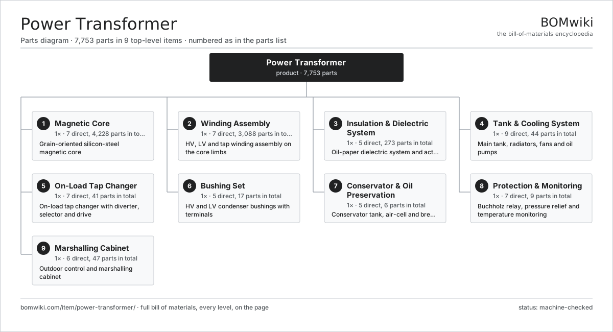
| # | Part | Qty | What it does |
|---|---|---|---|
| 1 | Magnetic Core 7 parts | 1× | Grain-oriented silicon-steel magnetic core |
| 2 | Winding Assembly 7 parts | 1× | HV, LV and tap winding assembly on the core limbs |
| 3 | Insulation & Dielectric System 5 parts | 1× | Oil-paper dielectric system and active-part insulation |
| 4 | Tank & Cooling System 9 parts | 1× | Main tank, radiators, fans and oil pumps |
| 5 | On-Load Tap Changer 7 parts | 1× | On-load tap changer with diverter, selector and drive |
| 6 | Bushing Set 5 parts | 1× | HV and LV condenser bushings with terminals |
| 7 | Conservator & Oil Preservation 5 parts | 1× | Conservator tank, air-cell and breather |
| 8 | Protection & Monitoring 7 parts | 1× | Buchholz relay, pressure relief and temperature monitoring |
| 9 | Marshalling Cabinet 6 parts | 1× | Outdoor control and marshalling cabinet |
3D model
No 3D model yet. Have a CAD file of this? Add a 3D model. STL renders right on this page; STEP, FreeCAD, and OpenSCAD sources are welcome too (openly licensed, like all 3D models on BOMwiki).
Build & assembly graph
expand / collapse · shared sub-assemblies converge · links to related products · est. labourTap an assembly to expand/collapse · tap a part to open it · use “Open page” for any node · drag to pan, scroll to zoom.
Bill of materials for Power Transformer
9 top-level lines · 81 rows shown · 7,753 parts total · indented to 3 levels| # | Item / sub-assembly | Part no. | Qty/assy | Ext. qty | Parts | Type |
|---|---|---|---|---|---|---|
| 1 | Magnetic Core 7 parts | power-transformer-core | 1× | 1 | 4,228 | assembly |
| 1.1 | GO Silicon-Steel Lamination | power-transformer-core-lamination | 4200× | 4,200 | · | part |
| 1.2 | Core Limb | power-transformer-core-limb | 3× | 3 | · | part |
| 1.3 | Core Yoke | power-transformer-core-yoke | 2× | 2 | · | part |
| 1.4 | Core Clamping Frame | power-transformer-clamping-frame | 2× | 2 | · | part |
| 1.5 | Core Tie Rod | power-transformer-core-tie-rod | 8× | 8 | · | part |
| 1.6 | Core Earthing Strap | power-transformer-core-ground-strap | 1× | 1 | · | part |
| 1.7 | Glass-Fibre Core Band | power-transformer-core-band | 12× | 12 | · | part |
| 2 | Winding Assembly 7 parts | power-transformer-windings | 1× | 1 | 3,088 | assembly |
| 2.1 | HV Disc Winding 4 parts | power-transformer-hv-winding | 3× | 3 | 244 | assembly |
| 2.1.1 | Paper-Covered Copper Conductor | power-transformer-copper-conductor | 1× | 3 | · | part |
| 2.1.2 | Kraft Paper Insulation | power-transformer-paper-insulation | 1× | 3 | · | part |
| 2.1.3 | Electrostatic Static Ring | power-transformer-static-ring | 2× | 6 | · | part |
| 2.1.4 | Pressboard Spacer | power-transformer-pressboard-spacer | 240× | 720 | · | part |
| 2.2 | LV Helical Winding 3 parts | power-transformer-lv-winding | 3× | 3 | 162 | assembly |
| 2.2.1 | Transposed Copper Conductor | power-transformer-ctc-conductor | 1× | 3 | · | part |
| 2.2.2 | Kraft Paper Insulation | power-transformer-paper-insulation | 1× | 3 | · | part |
| 2.2.3 | Pressboard Spacer | power-transformer-pressboard-spacer | 160× | 480 | · | part |
| 2.3 | Tap Winding 3 parts | power-transformer-tap-winding | 3× | 3 | 19 | assembly |
| 2.3.1 | Paper-Covered Copper Conductor | power-transformer-copper-conductor | 1× | 3 | · | part |
| 2.3.2 | Tap Lead | power-transformer-tap-lead | 17× | 51 | · | part |
| 2.3.3 | Kraft Paper Insulation | power-transformer-paper-insulation | 1× | 3 | · | part |
| 2.4 | Pressboard Spacer | power-transformer-pressboard-spacer | 1800× | 1,800 | · | part |
| 2.5 | Pressboard Barrier Cylinder | power-transformer-pressboard-cylinder | 6× | 6 | · | part |
| 2.6 | Winding Clamping Ring | power-transformer-winding-clamping-ring | 6× | 6 | · | part |
| 2.7 | Lead Exit Assembly | power-transformer-lead-exit | 1× | 1 | · | part |
| 3 | Insulation & Dielectric System 5 parts | power-transformer-insulation | 1× | 1 | 273 | assembly |
| 3.1 | Mineral Insulating Oil | power-transformer-mineral-oil | 1× | 1 | · | part |
| 3.2 | Pressboard Angle Ring | power-transformer-angle-ring | 60× | 60 | · | part |
| 3.3 | Lead Snout | power-transformer-snout | 6× | 6 | · | part |
| 3.4 | Oil Duct Stick | power-transformer-oil-duct-stick | 200× | 200 | · | part |
| 3.5 | End Insulation Block | power-transformer-end-insulation | 6× | 6 | · | part |
| 4 | Tank & Cooling System 9 parts | power-transformer-tank-cooling | 1× | 1 | 44 | assembly |
| 4.1 | Main Tank | power-transformer-main-tank | 1× | 1 | · | part |
| 4.2 | Tank Cover | power-transformer-tank-cover | 1× | 1 | · | part |
| 4.3 | Panel Radiator | power-transformer-radiator | 12× | 12 | · | part |
| 4.4 | Radiator Cooling Fan | power-transformer-cooling-fan | 16× | 16 | · | part |
| 4.5 | Oil Circulation Pump | power-transformer-oil-pump | 2× | 2 | · | part |
| 4.6 | Tank Valve | power-transformer-tank-valve | 8× | 8 | · | part |
| 4.7 | Oil Flow Indicator | power-transformer-flow-indicator | 2× | 2 | · | part |
| 4.8 | Fastener Set | fastener-set | 1× | 1 | · | part |
| 4.9 | O-Ring Set | oring-set | 1× | 1 | · | part |
| 5 | On-Load Tap Changer 7 parts | power-transformer-oltc | 1× | 1 | 41 | assembly |
| 5.1 | Diverter Switch | power-transformer-oltc-diverter | 1× | 1 | · | part |
| 5.2 | Tap Selector | power-transformer-oltc-selector | 1× | 1 | · | part |
| 5.3 | OLTC Motor Drive Unit 4 parts | power-transformer-oltc-motor-drive | 1× | 1 | 32 | assembly |
| 5.3.1 | Servo Motor 4 parts + deeper › | servo-motor | 1× | 1 | 24 | assembly |
| 5.3.2 | Drive Cam Shaft | power-transformer-oltc-cam | 1× | 1 | · | part |
| 5.3.3 | Relay | relay | 6× | 6 | · | part |
| 5.3.4 | Manual Operating Crank | power-transformer-oltc-hand-crank | 1× | 1 | · | part |
| 5.4 | Transition Resistor | power-transformer-oltc-transition-resistor | 4× | 4 | · | part |
| 5.5 | OLTC Oil Compartment | power-transformer-oltc-oil-compartment | 1× | 1 | · | part |
| 5.6 | Helical Gear Pair | gear-pair | 1× | 1 | · | part |
| 5.7 | Tap Position Counter | power-transformer-oltc-tap-counter | 1× | 1 | · | part |
| 6 | Bushing Set 5 parts | power-transformer-bushings | 1× | 1 | 17 | assembly |
| 6.1 | HV Condenser Bushing | power-transformer-hv-bushing | 3× | 3 | · | part |
| 6.2 | LV Bushing | power-transformer-lv-bushing | 3× | 3 | · | part |
| 6.3 | Neutral Bushing | power-transformer-neutral-bushing | 1× | 1 | · | part |
| 6.4 | Bushing Current Transformer | power-transformer-bushing-ct | 6× | 6 | · | part |
| 6.5 | Bushing Turret | power-transformer-bushing-turret | 4× | 4 | · | part |
| 7 | Conservator & Oil Preservation 5 parts | power-transformer-conservator | 1× | 1 | 6 | assembly |
| 7.1 | Conservator Tank | power-transformer-conservator-tank | 1× | 1 | · | part |
| 7.2 | Conservator Air-Cell | power-transformer-air-cell | 1× | 1 | · | part |
| 7.3 | Silica-Gel Breather | power-transformer-silica-breather | 1× | 1 | · | part |
| 7.4 | Magnetic Oil Level Gauge | power-transformer-magnetic-oil-gauge | 1× | 1 | · | part |
| 7.5 | Conservator Valve | power-transformer-conservator-valve | 2× | 2 | · | part |
| 8 | Protection & Monitoring 7 parts | power-transformer-protection | 1× | 1 | 9 | assembly |
| 8.1 | Buchholz Relay | power-transformer-buchholz-relay | 1× | 1 | · | part |
| 8.2 | Pressure Relief Device | power-transformer-pressure-relief | 2× | 2 | · | part |
| 8.3 | Sudden-Pressure Relay | power-transformer-sudden-pressure-relay | 1× | 1 | · | part |
| 8.4 | Winding Temperature Indicator | power-transformer-wti | 1× | 1 | · | part |
| 8.5 | Oil Temperature Indicator | power-transformer-oti | 1× | 1 | · | part |
| 8.6 | Pressure Sensor | pressure-sensor | 2× | 2 | · | part |
| 8.7 | Dissolved-Gas Monitor | power-transformer-dga-monitor | 1× | 1 | · | part |
| 9 | Marshalling Cabinet 6 parts | power-transformer-marshalling-cabinet | 1× | 1 | 47 | assembly |
| 9.1 | Sheet Metal Panel | sheet-panel | 6× | 6 | · | part |
| 9.2 | Cooler Control Unit | power-transformer-cooler-control | 1× | 1 | · | part |
| 9.3 | Relay | relay | 8× | 8 | · | part |
| 9.4 | Marshalling Terminal Block | power-transformer-terminal-block | 30× | 30 | · | part |
| 9.5 | Wire Bundle | wire-bundle | 1× | 1 | · | part |
| 9.6 | Cabinet Anti-Condensation Heater | power-transformer-cabinet-heater | 1× | 1 | · | part |
Related products
same domain, ranked by shared parts Autotransformer
7,784 parts · shares 17 with this page
Bottom Ash Handling System
1,782 parts · shares 17 with this page
Autotransformer
7,784 parts · shares 17 with this page
Bottom Ash Handling System
1,782 parts · shares 17 with this page
 Combined Heat and Power Unit
522 parts · shares 17 with this page
Combined Heat and Power Unit
522 parts · shares 17 with this page
 Gas-Insulated Switchgear
281 parts · shares 17 with this page
Gas-Insulated Switchgear
281 parts · shares 17 with this page
 Large Power Transformer
1,844 parts · shares 17 with this page
Large Power Transformer
1,844 parts · shares 17 with this page
 SCR NOx Reduction Unit
569 parts · shares 17 with this page
SCR NOx Reduction Unit
569 parts · shares 17 with this page
Sourcing: possible vendors
Browse the supplier directory → Prices, MOQ, and lead times are algorithmic estimates, not quotes, and not claims about these companies. Company mappings are curated by keyword; est. price band $5k–$50M. How estimates work| Vendor | HQ | Specialty | MOQ | Lead time |
|---|---|---|---|---|
| gevernova.com ↗ | Cambridge, US | Power generation | made to order | 20–40 wks |
| siemens-energy.com ↗ | Munich, DE | Power & grid | made to order | 20–40 wks |
| hitachienergy.com ↗ | Zurich, CH | Grid & transformers | made to order | 20–40 wks |
|
🇨🇭ABB
abb.com ↗
|
Zurich, CH | Electrification & automation | made to order | 20–40 wks |
| se.com ↗ | Rueil-Malmaison, FR | Electrical & automation | made to order | 20–40 wks |
1,047-word article