Shunt Reactor
ProductOverview
A shunt reactor is, in effect, an inductor for a high-voltage transmission line. It is connected from line to earth and absorbs reactive power, the opposite of a capacitor bank. Long extra-high-voltage lines and cables behave as large capacitors: at light load they generate reactive power and push the line voltage up, sometimes far above the nominal value, an effect that becomes severe on lightly loaded 400 kV and 765 kV circuits and on long cable systems. A shunt reactor draws an inductive (lagging) current that cancels that capacitive generation, holding the line voltage near its target. Ratings run from tens of megavars on a single line to several hundred megavars in banks, at voltage classes from 132 kV up to 800 kV.
Unlike a transformer, a shunt reactor has only one winding per phase and no secondary; it is built to present a precise, stable inductance rather than to transfer power. The most important design feature is the gapped core. The gaps make the inductance almost independent of the steel's non-linear magnetisation, so the reactor draws a clean, nearly sinusoidal current and stays linear up to about 1.5 times rated voltage. That linearity is what lets it hold voltage during the switching surges and load rejections where it is needed most.
The gapped core
The magnetic core is what sets a shunt reactor apart. Instead of a continuous steel limb, each limb is split into a series of short core packets separated by precise non-magnetic gap spacers of ceramic or high-density pressboard. The reluctance of these gaps dominates the magnetic circuit, so the inductance is fixed by the gap geometry rather than by the steel, which is why the reactor stays linear and its var rating is so repeatable. The gaps come at a cost: each gap face carries a strong fringing flux and a large pulsating magnetic pull, which is the main source of vibration and audible hum. The packets are squeezed by high-tension tie rods and a heavy clamping frame so the gaps cannot move, and flux shields collect the fringing flux to keep it from heating the tank and clamps.
Winding and insulation
The reactor winding surrounds the gapped limb and carries the full reactive line current. It is a disc-wound coil of transposed copper in kraft paper, with static rings grading the impulse field for the line voltage class. Because the gap forces vibrate the whole active part, the winding is held under axial pressure by spring-loaded clamps so it cannot loosen and buzz. The insulation system is standard oil-paper-pressboard practice with one special region: the insulation around the gaps is reinforced, because the concentrated fringing flux there would otherwise drive local eddy heating and partial discharge.
Tank, cooling and noise control
The active part sits in a stiffened steel tank cooled by radiators, ONAN at base rating and ONAF with fans at full load. Noise is a defining concern for shunt reactors, more so than for transformers, because magnetostriction and the magnetic pull at the gap faces both excite the structure at twice the line frequency. The noise-control system addresses this with vibration isolators decoupling the core from the tank, tank stiffeners that raise the wall's natural frequency away from the 100 or 120 Hz hum, and sound-attenuating panels. Reactors near communities are sometimes specified to tight sound limits that drive much of the mechanical design.
Bushings, conservator and protection
Three line bushings connect the phases and a neutral bushing brings out the star point, which on some long lines passes through a separate neutral reactor in a four-reactor scheme that aids single-pole auto-reclosing. Protection is thorough because a turn-to-turn fault in a single-winding reactor is hard to detect from the terminals: a Buchholz relay, sudden-pressure relay, and pressure-relief device guard against internal faults, temperature indicators watch loading, and many modern reactors add an online dissolved-gas monitor and a vibration sensor whose trend reveals loosening clamps or gap movement before a fault develops. The conservator with its air cell and silica-gel breather keeps moisture out, and the marshalling cabinet wires the auxiliaries to the substation.
Variants, standards and use
Shunt reactors are designed to IEC 60076-6 and IEEE C57.21. The main variants are the directly connected (bus or line) reactor that is permanently in circuit, the breaker-switched reactor that is brought in only at light load, and the variable shunt reactor whose inductance is adjusted by an on-load tap changer to track changing line conditions, an increasingly popular option as networks carry more variable renewable generation. Dry-type air-core reactors exist for lower voltages, but the gapped oil-immersed design described here dominates at transmission voltages. The application is voltage control: a shunt reactor is installed wherever a long overhead line or cable would otherwise overvolt at light load, at the line ends of EHV interconnectors, at cable terminations, and in substations feeding lightly loaded networks. It is one of the standard tools, alongside switched capacitor banks and static var compensators, that keep transmission voltage inside its operating band.
Shunt Reactor parts and their functions
9 top-level parts · 398 parts in total · full bill of materials below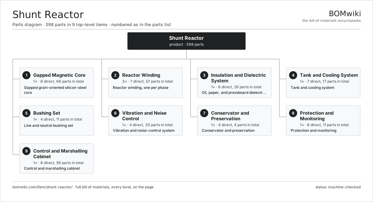
| # | Part | Qty | What it does |
|---|---|---|---|
| 1 | Gapped Magnetic Core 8 parts | 1× | Gapped grain-oriented silicon-steel core |
| 2 | Reactor Winding 7 parts | 3× | Reactor winding, one per phase |
| 3 | Insulation and Dielectric System 6 parts | 1× | Oil, paper, and pressboard dielectric system |
| 4 | Tank and Cooling System 7 parts | 1× | Tank and cooling system |
| 5 | Bushing Set 4 parts | 1× | Line and neutral bushing set |
| 6 | Vibration and Noise Control 4 parts | 1× | Vibration and noise-control system |
| 7 | Conservator and Preservation 4 parts | 1× | Conservator and preservation |
| 8 | Protection and Monitoring 8 parts | 1× | Protection and monitoring |
| 9 | Control and Marshalling Cabinet 8 parts | 1× | Control and marshalling cabinet |
3D model
No 3D model yet. Have a CAD file of this? Add a 3D model. STL renders right on this page; STEP, FreeCAD, and OpenSCAD sources are welcome too (openly licensed, like all 3D models on BOMwiki).
Build & assembly graph
expand / collapse · shared sub-assemblies converge · links to related products · est. labourTap an assembly to expand/collapse · tap a part to open it · use “Open page” for any node · drag to pan, scroll to zoom.
Bill of materials for Shunt Reactor
9 top-level lines · 65 rows shown · 398 parts total · indented to 3 levels| # | Item / sub-assembly | Part no. | Qty/assy | Ext. qty | Parts | Type |
|---|---|---|---|---|---|---|
| 1 | Gapped Magnetic Core 8 parts | shunt-reactor-gapped-core | 1× | 1 | 66 | assembly |
| 1.1 | GO Silicon-Steel Lamination | shunt-reactor-core-lamination | 1× | 1 | · | part |
| 1.2 | Core Packet | shunt-reactor-core-packet | 12× | 12 | · | part |
| 1.3 | Non-Magnetic Gap Spacer | shunt-reactor-air-gap-spacer | 30× | 30 | · | part |
| 1.4 | Core Yoke | shunt-reactor-core-yoke | 2× | 2 | · | part |
| 1.5 | Core Clamping Frame | shunt-reactor-core-clamp | 4× | 4 | · | part |
| 1.6 | High-Tension Tie Rod | shunt-reactor-core-tie-rod | 8× | 8 | · | part |
| 1.7 | Magnetic Flux Shield | shunt-reactor-flux-shield | 8× | 8 | · | part |
| 1.8 | Core Ground Strap | shunt-reactor-core-ground-strap | 1× | 1 | · | part |
| 2 | Reactor Winding 7 parts | shunt-reactor-winding | 3× | 3 | 57 | assembly |
| 2.1 | Reactor Copper Conductor | shunt-reactor-winding-conductor | 1× | 3 | · | part |
| 2.2 | Winding Disc Section | shunt-reactor-winding-disc | 1× | 3 | · | part |
| 2.3 | Winding Support Cylinder | shunt-reactor-winding-cylinder | 1× | 3 | · | part |
| 2.4 | Radial Spacer Block | shunt-reactor-spacer-block | 48× | 144 | · | part |
| 2.5 | Static Ring | shunt-reactor-static-ring | 2× | 6 | · | part |
| 2.6 | Axial Winding Clamp | shunt-reactor-axial-clamp | 2× | 6 | · | part |
| 2.7 | Winding Lead Exit | shunt-reactor-lead-exit | 2× | 6 | · | part |
| 3 | Insulation and Dielectric System 6 parts | shunt-reactor-insulation | 1× | 1 | 29 | assembly |
| 3.1 | Mineral Insulating Oil | shunt-reactor-mineral-oil | 1× | 1 | · | part |
| 3.2 | Kraft Paper Insulation | shunt-reactor-paper-insulation | 1× | 1 | · | part |
| 3.3 | Pressboard Barrier | shunt-reactor-pressboard-barrier | 12× | 12 | · | part |
| 3.4 | Pressboard Angle Ring | shunt-reactor-angle-ring | 8× | 8 | · | part |
| 3.5 | Gap-Region Insulation | shunt-reactor-gap-insulation | 1× | 1 | · | part |
| 3.6 | Lead Support Frame | shunt-reactor-lead-support | 6× | 6 | · | part |
| 4 | Tank and Cooling System 7 parts | shunt-reactor-tank-cooling | 1× | 1 | 17 | assembly |
| 4.1 | Reactor Tank | shunt-reactor-tank | 1× | 1 | · | part |
| 4.2 | Tank Cover | shunt-reactor-tank-cover | 1× | 1 | · | part |
| 4.3 | Cooling Radiator | shunt-reactor-radiator | 6× | 6 | · | part |
| 4.4 | Radiator Fan | shunt-reactor-cooling-fan | 6× | 6 | · | part |
| 4.5 | Oil Valve Set | shunt-reactor-valve-set | 1× | 1 | · | part |
| 4.6 | Transport Skid | shunt-reactor-skid | 1× | 1 | · | part |
| 4.7 | O-Ring Set | oring-set | 1× | 1 | · | part |
| 5 | Bushing Set 4 parts | shunt-reactor-bushings | 1× | 1 | 11 | assembly |
| 5.1 | HV Line Bushing | shunt-reactor-line-bushing | 3× | 3 | · | part |
| 5.2 | Neutral Bushing | shunt-reactor-neutral-bushing | 1× | 1 | · | part |
| 5.3 | Bushing Current Transformer | shunt-reactor-bushing-ct | 4× | 4 | · | part |
| 5.4 | Bushing Turret | shunt-reactor-bushing-turret | 3× | 3 | · | part |
| 6 | Vibration and Noise Control 4 parts | shunt-reactor-noise-control | 1× | 1 | 30 | assembly |
| 6.1 | Active-Part Vibration Isolator | shunt-reactor-vibration-isolator | 8× | 8 | · | part |
| 6.2 | Sound-Attenuating Panel | shunt-reactor-sound-panel | 6× | 6 | · | part |
| 6.3 | Tank Stiffener | shunt-reactor-tank-stiffener | 8× | 8 | · | part |
| 6.4 | Coil Spring | coil-spring | 8× | 8 | · | part |
| 7 | Conservator and Preservation 4 parts | shunt-reactor-conservator | 1× | 1 | 4 | assembly |
| 7.1 | Conservator Tank | shunt-reactor-conservator-tank | 1× | 1 | · | part |
| 7.2 | Conservator Air Cell | shunt-reactor-air-cell | 1× | 1 | · | part |
| 7.3 | Silica-Gel Breather | shunt-reactor-silica-breather | 1× | 1 | · | part |
| 7.4 | Magnetic Oil-Level Gauge | shunt-reactor-oil-level-gauge | 1× | 1 | · | part |
| 8 | Protection and Monitoring 8 parts | shunt-reactor-protection | 1× | 1 | 11 | assembly |
| 8.1 | Buchholz Relay | shunt-reactor-buchholz | 1× | 1 | · | part |
| 8.2 | Pressure-Relief Device | shunt-reactor-pressure-relief | 1× | 1 | · | part |
| 8.3 | Sudden-Pressure Relay | shunt-reactor-sudden-pressure-relay | 1× | 1 | · | part |
| 8.4 | Winding Temperature Indicator | shunt-reactor-winding-temp | 2× | 2 | · | part |
| 8.5 | Top-Oil Temperature Indicator | shunt-reactor-oil-temp | 1× | 1 | · | part |
| 8.6 | Tank Vibration Sensor | shunt-reactor-vibration-sensor | 2× | 2 | · | part |
| 8.7 | Pressure Sensor | pressure-sensor | 2× | 2 | · | part |
| 8.8 | Online DGA Monitor | shunt-reactor-dga-monitor | 1× | 1 | · | part |
| 9 | Control and Marshalling Cabinet 8 parts | shunt-reactor-marshalling | 1× | 1 | 59 | assembly |
| 9.1 | Marshalling Enclosure | shunt-reactor-cabinet-enclosure | 1× | 1 | · | part |
| 9.2 | Cooling-Stage Controller | shunt-reactor-cooling-controller | 1× | 1 | · | part |
| 9.3 | Relay | relay | 10× | 10 | · | part |
| 9.4 | Field Terminal Block | shunt-reactor-terminal-block | 32× | 32 | · | part |
| 9.5 | Wire Bundle | wire-bundle | 1× | 1 | · | part |
| 9.6 | Connector | connector | 12× | 12 | · | part |
| 9.7 | LCD Panel | lcd-panel | 1× | 1 | · | part |
| 9.8 | Cabinet Space Heater | shunt-reactor-space-heater | 1× | 1 | · | part |
Related products
same domain, ranked by shared parts Combined Heat and Power Unit
522 parts · shares 5 with this page
Combined Heat and Power Unit
522 parts · shares 5 with this page
 Distribution Ring Main Unit
443 parts · shares 5 with this page
Distribution Ring Main Unit
443 parts · shares 5 with this page
 Large Synchronous Generator
42,357 parts · shares 5 with this page
Large Synchronous Generator
42,357 parts · shares 5 with this page
 Electrostatic Precipitator
879 parts · shares 4 with this page
Electrostatic Precipitator
879 parts · shares 4 with this page
 Geothermal Wellhead
274 parts · shares 4 with this page
Geothermal Wellhead
274 parts · shares 4 with this page
Sourcing: possible vendors
Browse the supplier directory → Prices, MOQ, and lead times are algorithmic estimates, not quotes, and not claims about these companies. Company mappings are curated by keyword; est. price band $5k–$50M. How estimates work| Vendor | HQ | Specialty | MOQ | Lead time |
|---|---|---|---|---|
| gevernova.com ↗ | Cambridge, US | Power generation | made to order | 20–40 wks |
| siemens-energy.com ↗ | Munich, DE | Power & grid | made to order | 20–40 wks |
| hitachienergy.com ↗ | Zurich, CH | Grid & transformers | made to order | 20–40 wks |
|
🇨🇭ABB
abb.com ↗
|
Zurich, CH | Electrification & automation | made to order | 20–40 wks |
| se.com ↗ | Rueil-Malmaison, FR | Electrical & automation | made to order | 20–40 wks |
995-word article