Industrial Gas Turbine Package
ProductOverview
An industrial gas turbine package is a factory-assembled power plant on a skid: a gas turbine, a synchronous generator, and all the support systems needed to run them, mounted on a common base inside an acoustic enclosure. The unit in this article is a single-shaft machine rated around 35 MW at ISO conditions, burning pipeline natural gas at roughly 38% simple-cycle efficiency. Air is drawn through the Air Inlet System, compressed by the Axial Compressor, mixed with fuel and burned in the Combustion Section, expanded through the Turbine Section, and exhausted through the Exhaust System. The turbine drives both the compressor on its own shaft and the Generator through a load gear.
Packaging the whole train this way lets the unit ship as a small number of pre-tested modules, drop onto a prepared foundation, and connect to fuel, water, and switchgear with minimal site work. The same machine runs as a simple-cycle peaker, as the topping cycle for a combined-cycle plant feeding a heat-recovery boiler, or as mechanical drive for compressors and pumps.
Compressor and air path
Inlet air first passes the Filter House, where pulse-clean cartridge elements strip dust before it can foul the blading, then through an inlet silencer and duct to the compressor bellmouth. The Axial Compressor raises pressure across 17 axial stages to a 17:1 ratio. Each stage pairs a row of rotating Compressor Rotor Blade airfoils on the Compressor Rotor with a row of stationary Compressor Stator Vane vanes that deswirl and diffuse the flow.
The first row, the Variable Inlet Guide Vanes, is variable: a servo-driven unison ring pivots every Inlet Guide Vane together to match airflow to load and to hold a stable operating line during starting. At low speed the compressor would otherwise stall, so Anti-Surge Bleed Valve anti-surge valves dump intermediate-stage air until the machine accelerates. Tip clearances are controlled by abradable shroud strips that the blades cut into during the first runs.
Combustion
Compressed air enters the Combustion Section, an annular dry low-NOx design. Fuel reaches the engine through the Fuel Gas System, which coalesces out liquids, holds a steady supply pressure through a stop ratio valve, and meters flow with the Gas Control Valve. The Fuel Manifold splits gas evenly to 24 premix Premix Fuel Nozzle nozzles, which blend fuel and air upstream of the flame so the mixture burns lean and cool enough to keep NOx below 25 ppm without water or steam injection.
Light-off is handled by two retractable Spark Igniter igniters, with crossfire tubes carrying flame around the annulus and UV Flame Scanner scanners confirming a stable burn. Hot gas leaves the liner at roughly 1,400 °C and is routed to the turbine through cooled transition pieces.
Turbine and rotor
The Turbine Section expands the gas across four stages, dropping pressure and temperature while extracting the work that drives the compressor and generator. The first stages run hotter than their alloys could survive uncoated, so each Turbine Blade is a single-crystal casting with internal cooling passages fed by compressor bleed air and a ceramic Thermal Barrier Coating on its surface. Stationary Nozzle Guide Vane Row rows accelerate and turn the flow onto each blade row.
Compressor and turbine share one Main Shaft, carried by the Rotor and Bearing System. Tilting-pad Tilting-Pad Journal Bearing bearings support the rotor radially and a Thrust Bearing takes the net axial load. After shutdown a Turning Gear rolls the hot rotor slowly so it cools evenly and does not bow. Torque passes to the generator through a flexible coupling and load gear that steps the 6,500 rpm turbine speed down to the 3,000 rpm the generator needs for 50 Hz.
Generator and electrical
The Generator is a synchronous AC machine using a shared Generator stator and field rotor. A brushless Brushless Exciter supplies the rotor field, and an air-to-water Generator Cooler removes winding heat. Output leaves through high-voltage bushings in the terminal box to the plant switchgear. On start, the same generator runs as a motor: the Starting System static converter cranks the shaft up to self-sustaining speed, after which the starting clutch disengages and the turbine carries itself.
Auxiliaries and controls
The Accessory System hangs off the load end of the shaft. Its Accessory Gearbox drives the pumps of the Lube Oil System, which keeps filtered, cooled oil flowing to every bearing and gear mesh, with an electric auxiliary pump covering start, stop, and any loss of the main pump.
Everything is wrapped in the Acoustic Enclosure: acoustic panels hold package noise to about 85 dBA, ventilation fans purge any leaked fuel, and gas detectors plus a fire-suppression skid guard the compartment. The Control System runs the machine through redundant controllers that schedule fuel, position the guide vanes, sequence starts, and trip the turbine on overspeed, high vibration, or flame loss. Triple speed pickups and eight vibration probes feed the protection logic, and a panel display gives the operator turbine status at the package.
Industrial Gas Turbine Package parts and their functions
11 top-level parts · 2,053 parts in total · full bill of materials below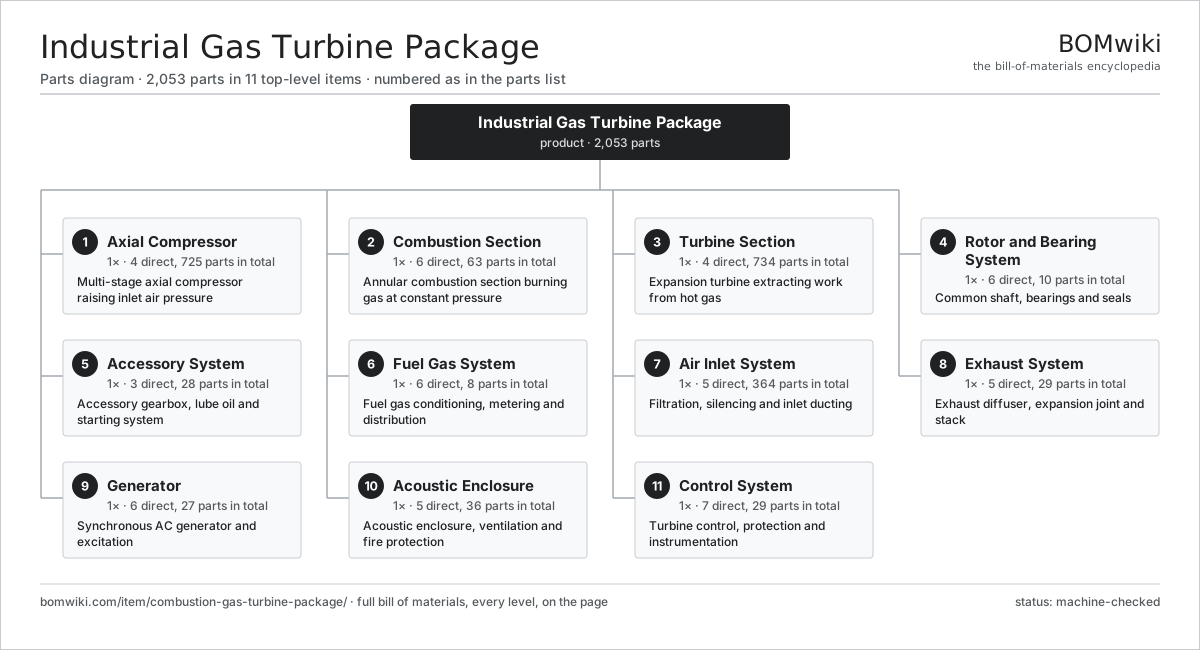
| # | Part | Qty | What it does |
|---|---|---|---|
| 1 | Axial Compressor 4 parts | 1× | Multi-stage axial compressor raising inlet air pressure |
| 2 | Combustion Section 6 parts | 1× | Annular combustion section burning gas at constant pressure |
| 3 | Turbine Section 4 parts | 1× | Expansion turbine extracting work from hot gas |
| 4 | Rotor and Bearing System 6 parts | 1× | Common shaft, bearings and seals |
| 5 | Accessory System 3 parts | 1× | Accessory gearbox, lube oil and starting system |
| 6 | Fuel Gas System 6 parts | 1× | Fuel gas conditioning, metering and distribution |
| 7 | Air Inlet System 5 parts | 1× | Filtration, silencing and inlet ducting |
| 8 | Exhaust System 5 parts | 1× | Exhaust diffuser, expansion joint and stack |
| 9 | Generator 6 parts | 1× | Synchronous AC generator and excitation |
| 10 | Acoustic Enclosure 5 parts | 1× | Acoustic enclosure, ventilation and fire protection |
| 11 | Control System 7 parts | 1× | Turbine control, protection and instrumentation |
3D model
No 3D model yet. Have a CAD file of this? Add a 3D model. STL renders right on this page; STEP, FreeCAD, and OpenSCAD sources are welcome too (openly licensed, like all 3D models on BOMwiki).
Build & assembly graph
expand / collapse · shared sub-assemblies converge · links to related products · est. labourTap an assembly to expand/collapse · tap a part to open it · use “Open page” for any node · drag to pan, scroll to zoom.
Bill of materials for Industrial Gas Turbine Package
11 top-level lines · 104 rows shown · 2,053 parts total · indented to 3 levels| # | Item / sub-assembly | Part no. | Qty/assy | Ext. qty | Parts | Type |
|---|---|---|---|---|---|---|
| 1 | Axial Compressor 4 parts | combustion-gas-turbine-package-axial-compressor | 1× | 1 | 725 | assembly |
| 1.1 | Compressor Rotor 4 parts | combustion-gas-turbine-package-compressor-rotor | 1× | 1 | 309 | assembly |
| 1.1.1 | Compressor Rotor Blade | combustion-gas-turbine-package-rotor-blade | 272× | 272 | · | part |
| 1.1.2 | Compressor Disc | combustion-gas-turbine-package-rotor-disc | 17× | 17 | · | part |
| 1.1.3 | Rotor Tie Bolt | combustion-gas-turbine-package-tie-bolt | 12× | 12 | · | part |
| 1.1.4 | Balance Weight | combustion-gas-turbine-package-balance-weight | 8× | 8 | · | part |
| 1.2 | Compressor Stator 4 parts | combustion-gas-turbine-package-compressor-stator | 1× | 1 | 291 | assembly |
| 1.2.1 | Compressor Stator Vane | combustion-gas-turbine-package-stator-vane | 272× | 272 | · | part |
| 1.2.2 | Compressor Casing | combustion-gas-turbine-package-compressor-casing | 1× | 1 | · | part |
| 1.2.3 | Abradable Shroud Segment | combustion-gas-turbine-package-abradable-shroud | 17× | 17 | · | part |
| 1.2.4 | Fastener Set | fastener-set | 1× | 1 | · | part |
| 1.3 | Variable Inlet Guide Vanes 4 parts | combustion-gas-turbine-package-igv-assembly | 1× | 1 | 121 | assembly |
| 1.3.1 | Inlet Guide Vane | combustion-gas-turbine-package-igv-vane | 48× | 48 | · | part |
| 1.3.2 | IGV Unison Ring | combustion-gas-turbine-package-igv-ring | 1× | 1 | · | part |
| 1.3.3 | Servo Motor 4 parts + deeper › | servo-motor | 1× | 1 | 24 | assembly |
| 1.3.4 | IGV Trunnion Bushing | combustion-gas-turbine-package-igv-bushing | 48× | 48 | · | part |
| 1.4 | Anti-Surge Bleed Valve | combustion-gas-turbine-package-bleed-valve | 4× | 4 | · | part |
| 2 | Combustion Section 6 parts | combustion-gas-turbine-package-combustor | 1× | 1 | 63 | assembly |
| 2.1 | Premix Fuel Nozzle | combustion-gas-turbine-package-fuel-nozzle | 24× | 24 | · | part |
| 2.2 | Combustion Liner | combustion-gas-turbine-package-combustion-liner | 1× | 1 | · | part |
| 2.3 | Transition Piece | combustion-gas-turbine-package-transition-piece | 16× | 16 | · | part |
| 2.4 | Spark Igniter | combustion-gas-turbine-package-igniter | 2× | 2 | · | part |
| 2.5 | Flame Scanner | combustion-gas-turbine-package-flame-detector | 4× | 4 | · | part |
| 2.6 | Crossfire Tube | combustion-gas-turbine-package-crossfire-tube | 16× | 16 | · | part |
| 3 | Turbine Section 4 parts | combustion-gas-turbine-package-turbine-section | 1× | 1 | 734 | assembly |
| 3.1 | Turbine Rotor 4 parts | combustion-gas-turbine-package-turbine-rotor | 1× | 1 | 728 | assembly |
| 3.1.1 | Turbine Blade | combustion-gas-turbine-package-turbine-blade | 360× | 360 | · | part |
| 3.1.2 | Turbine Disc | combustion-gas-turbine-package-turbine-disc | 4× | 4 | · | part |
| 3.1.3 | Blade Retainer | combustion-gas-turbine-package-blade-retainer | 4× | 4 | · | part |
| 3.1.4 | Thermal Barrier Coating | combustion-gas-turbine-package-thermal-barrier-coating | 360× | 360 | · | part |
| 3.2 | Nozzle Guide Vane Row | combustion-gas-turbine-package-nozzle-guide-vane | 4× | 4 | · | part |
| 3.3 | Turbine Casing | combustion-gas-turbine-package-turbine-casing | 1× | 1 | · | part |
| 3.4 | Cooling Air Manifold | combustion-gas-turbine-package-cooling-air-manifold | 1× | 1 | · | part |
| 4 | Rotor and Bearing System 6 parts | combustion-gas-turbine-package-rotor-bearing-system | 1× | 1 | 10 | assembly |
| 4.1 | Main Shaft | combustion-gas-turbine-package-main-shaft | 1× | 1 | · | part |
| 4.2 | Tilting-Pad Journal Bearing | combustion-gas-turbine-package-journal-bearing | 2× | 2 | · | part |
| 4.3 | Thrust Bearing | combustion-gas-turbine-package-thrust-bearing | 1× | 1 | · | part |
| 4.4 | Labyrinth Seal | combustion-gas-turbine-package-labyrinth-seal | 4× | 4 | · | part |
| 4.5 | Flexible Coupling | combustion-gas-turbine-package-flexible-coupling | 1× | 1 | · | part |
| 4.6 | Turning Gear | combustion-gas-turbine-package-turning-gear | 1× | 1 | · | part |
| 5 | Accessory System 3 parts | combustion-gas-turbine-package-accessory-system | 1× | 1 | 28 | assembly |
| 5.1 | Accessory Gearbox 4 parts | combustion-gas-turbine-package-accessory-gearbox | 1× | 1 | 14 | assembly |
| 5.1.1 | Helical Gear Pair | gear-pair | 3× | 3 | · | part |
| 5.1.2 | Gearbox Housing | gearbox-housing | 1× | 1 | · | part |
| 5.1.3 | Ball Bearing | ball-bearing | 6× | 6 | · | part |
| 5.1.4 | Oil Seal | oil-seal | 4× | 4 | · | part |
| 5.2 | Lube Oil System 6 parts | combustion-gas-turbine-package-lube-oil-system | 1× | 1 | 11 | assembly |
| 5.2.1 | Oil Reservoir | combustion-gas-turbine-package-oil-reservoir | 1× | 1 | · | part |
| 5.2.2 | Main Oil Pump | combustion-gas-turbine-package-main-oil-pump | 1× | 1 | · | part |
| 5.2.3 | Auxiliary Oil Pump | combustion-gas-turbine-package-aux-oil-pump | 1× | 1 | · | part |
| 5.2.4 | Oil Cooler | combustion-gas-turbine-package-oil-cooler | 2× | 2 | · | part |
| 5.2.5 | Oil Filter | combustion-gas-turbine-package-oil-filter | 2× | 2 | · | part |
| 5.2.6 | Pressure Sensor | pressure-sensor | 4× | 4 | · | part |
| 5.3 | Starting System 3 parts | combustion-gas-turbine-package-starting-system | 1× | 1 | 3 | assembly |
| 5.3.1 | Static Starter | combustion-gas-turbine-package-static-starter | 1× | 1 | · | part |
| 5.3.2 | Starting Clutch | combustion-gas-turbine-package-start-clutch | 1× | 1 | · | part |
| 5.3.3 | Power Supply | power-supply | 1× | 1 | · | part |
| 6 | Fuel Gas System 6 parts | combustion-gas-turbine-package-fuel-gas-system | 1× | 1 | 8 | assembly |
| 6.1 | Gas Coalescing Filter | combustion-gas-turbine-package-gas-filter | 1× | 1 | · | part |
| 6.2 | Stop Ratio Valve | combustion-gas-turbine-package-stop-ratio-valve | 1× | 1 | · | part |
| 6.3 | Gas Control Valve | combustion-gas-turbine-package-gas-control-valve | 1× | 1 | · | part |
| 6.4 | Fuel Manifold | combustion-gas-turbine-package-fuel-manifold | 1× | 1 | · | part |
| 6.5 | Fuel Vent Valve | combustion-gas-turbine-package-vent-valve | 1× | 1 | · | part |
| 6.6 | Pressure Sensor | pressure-sensor | 3× | 3 | · | part |
| 7 | Air Inlet System 5 parts | combustion-gas-turbine-package-air-inlet-system | 1× | 1 | 364 | assembly |
| 7.1 | Filter House | combustion-gas-turbine-package-filter-house | 1× | 1 | · | part |
| 7.2 | Inlet Filter Element | combustion-gas-turbine-package-inlet-filter-element | 360× | 360 | · | part |
| 7.3 | Inlet Silencer | combustion-gas-turbine-package-inlet-silencer | 1× | 1 | · | part |
| 7.4 | Inlet Duct | combustion-gas-turbine-package-inlet-duct | 1× | 1 | · | part |
| 7.5 | Inlet Trash Screen | combustion-gas-turbine-package-trash-screen | 1× | 1 | · | part |
| 8 | Exhaust System 5 parts | combustion-gas-turbine-package-exhaust-system | 1× | 1 | 29 | assembly |
| 8.1 | Exhaust Diffuser | combustion-gas-turbine-package-exhaust-diffuser | 1× | 1 | · | part |
| 8.2 | Expansion Joint | combustion-gas-turbine-package-expansion-joint | 2× | 2 | · | part |
| 8.3 | Exhaust Silencer | combustion-gas-turbine-package-exhaust-silencer | 1× | 1 | · | part |
| 8.4 | Exhaust Stack | combustion-gas-turbine-package-exhaust-stack | 1× | 1 | · | part |
| 8.5 | Exhaust Thermocouple | combustion-gas-turbine-package-exhaust-thermocouple | 24× | 24 | · | part |
| 9 | Generator 6 parts | combustion-gas-turbine-package-generator | 1× | 1 | 27 | assembly |
| 9.1 | Stator Assembly 3 parts | stator-assembly | 1× | 1 | 3 | assembly |
| 9.1.1 | Stator Core (laminations) | stator-core | 1× | 1 | · | part |
| 9.1.2 | Copper Winding | copper-winding | 1× | 1 | · | part |
| 9.1.3 | Slot Insulation | stator-insulation | 1× | 1 | · | part |
| 9.2 | Rotor Assembly 4 parts | rotor-assembly | 1× | 1 | 19 | assembly |
| 9.2.1 | Rotor Shaft | rotor-shaft | 1× | 1 | · | part |
| 9.2.2 | Rotor Core | rotor-core | 1× | 1 | · | part |
| 9.2.3 | Neodymium Magnet | neodymium-magnet | 16× | 16 | · | part |
| 9.2.4 | Ball Bearing | ball-bearing | 1× | 1 | · | part |
| 9.3 | Brushless Exciter | combustion-gas-turbine-package-exciter | 1× | 1 | · | part |
| 9.4 | Generator Bearing | combustion-gas-turbine-package-generator-bearing | 2× | 2 | · | part |
| 9.5 | Generator Cooler | combustion-gas-turbine-package-generator-cooler | 1× | 1 | · | part |
| 9.6 | Generator Terminal Box | combustion-gas-turbine-package-terminal-box | 1× | 1 | · | part |
| 10 | Acoustic Enclosure 5 parts | combustion-gas-turbine-package-enclosure | 1× | 1 | 36 | assembly |
| 10.1 | Acoustic Panel | combustion-gas-turbine-package-enclosure-panel | 28× | 28 | · | part |
| 10.2 | Ventilation Fan | combustion-gas-turbine-package-ventilation-fan | 2× | 2 | · | part |
| 10.3 | Fire Suppression Skid | combustion-gas-turbine-package-fire-suppression | 1× | 1 | · | part |
| 10.4 | Gas Detector | combustion-gas-turbine-package-gas-detector | 4× | 4 | · | part |
| 10.5 | Base Frame | combustion-gas-turbine-package-base-frame | 1× | 1 | · | part |
| 11 | Control System 7 parts | combustion-gas-turbine-package-control-system | 1× | 1 | 29 | assembly |
| 11.1 | Control Cabinet | combustion-gas-turbine-package-control-cabinet | 1× | 1 | · | part |
| 11.2 | Turbine Controller Card | combustion-gas-turbine-package-controller-card | 3× | 3 | · | part |
| 11.3 | I/O Card | combustion-gas-turbine-package-io-card | 12× | 12 | · | part |
| 11.4 | LCD Panel | lcd-panel | 1× | 1 | · | part |
| 11.5 | Speed Pickup | combustion-gas-turbine-package-speed-pickup | 3× | 3 | · | part |
| 11.6 | Vibration Probe | combustion-gas-turbine-package-vibration-probe | 8× | 8 | · | part |
| 11.7 | Wire Bundle | wire-bundle | 1× | 1 | · | part |
Related products
same domain, ranked by shared parts Coal Pulverizer Mill
313 parts · shares 19 with this page
Coal Pulverizer Mill
313 parts · shares 19 with this page
 Combined Heat and Power Unit
522 parts · shares 19 with this page
Combined Heat and Power Unit
522 parts · shares 19 with this page
 Large Power Transformer
1,844 parts · shares 17 with this page
Large Power Transformer
1,844 parts · shares 17 with this page
 Automatic Voltage Regulator
83 parts · shares 16 with this page
Automatic Voltage Regulator
83 parts · shares 16 with this page
 SCR NOx Reduction Unit
569 parts · shares 18 with this page
SCR NOx Reduction Unit
569 parts · shares 18 with this page
Sourcing: possible vendors
Browse the supplier directory → Prices, MOQ, and lead times are algorithmic estimates, not quotes, and not claims about these companies. Company mappings are curated by keyword; est. price band $5k–$50M. How estimates work| Vendor | HQ | Specialty | MOQ | Lead time |
|---|---|---|---|---|
| gevernova.com ↗ | Cambridge, US | Power generation | made to order | 20–40 wks |
| siemens-energy.com ↗ | Munich, DE | Power & grid | made to order | 20–40 wks |
| hitachienergy.com ↗ | Zurich, CH | Grid & transformers | made to order | 20–40 wks |
|
🇨🇭ABB
abb.com ↗
|
Zurich, CH | Electrification & automation | made to order | 20–40 wks |
| se.com ↗ | Rueil-Malmaison, FR | Electrical & automation | made to order | 20–40 wks |
994-word article