Autotransformer
ProductOverview
An Autotransformer connects two transmission voltage levels using a single winding per phase that both circuits share, instead of two electrically separate windings. Part of the winding, the common winding, is shared by the high and intermediate voltage circuits; the rest, the series winding, is in series with it and supplies the voltage difference. Because the two circuits are electrically connected as well as magnetically coupled, only the difference in power has to be transformed magnetically. The rest passes straight through by conduction.
That property is the whole reason autotransformers exist. For two voltages that are close in ratio, say 400 kV to 220 kV, the magnetically transformed power is only a fraction of the throughput, so the core and windings can be much smaller, lighter and cheaper than a two-winding Power Transformer of the same MVA. The penalty is that the two systems are no longer galvanically isolated, and the unit must be applied where that shared connection is acceptable, which is normal between two earthed transmission systems.
The autoconnection and co-ratio
The economy is captured by the co-ratio, the fraction of rated throughput that is actually transformed. It equals one minus the ratio of the lower voltage to the higher. For a 400/220 kV unit the co-ratio is about 0.45, meaning the active part is sized for roughly 45 percent of the nameplate MVA. The closer the two voltages, the smaller this fraction and the greater the saving. This is why autotransformers dominate transmission interties where ratios are modest, and why they are rarely used for large step-down ratios where the saving disappears.
Core and windings
The Magnetic Core is a grain-oriented silicon-steel core with three limbs and two yokes, held by clamping frames and earthed through the earthing strap. Flux shunts keep stray flux off the tank.
The common winding sits on the limb and carries only the difference current, so it can be wound from transposed conductor sized below the full throughput. The series winding adds the voltage difference and is graded for impulse with static rings. A closed delta tertiary is almost always fitted: it gives a low-impedance path for triplen (third-harmonic) currents so the magnetising flux stays sinusoidal and the neutral stays stable, and it can also supply station auxiliaries or carry reactive compensation. A tap winding feeds the on-load tap changer. The whole stack is insulated with kraft paper, barrier cylinders and pressboard spacers.
Insulation and dielectric
Because the HV and IV circuits share a winding, the insulation system needs careful field grading at the junction where the series and common windings meet. The mineral oil fills and cools the active part, while angle rings and end blocks shape the field at the high-stress edges. The neutral end is only lightly insulated, which is reflected in the much lower neutral BIL on the nameplate.
Cooling, bushings and tap changer
The tank and cooling system is conventional: a welded tank with radiators, fans and pumps giving ONAN, ONAF and OFAF stages. Connections cross the tank cover through bushings: HV and IV condenser bushings for the two transmission levels, tertiary bushings for the delta, and a neutral bushing at the shared star point.
Ratio control is by on-load tap changer. The selector pre-selects a tap and the diverter switch transfers load current with transition resistors, driven by the motor drive. Tap-changer placement on an autotransformer needs care because the regulating turns interact with both circuits, and designs differ in whether the taps sit at the line end or the neutral end of the winding.
Protection, preservation and application
Oil volume change is taken up by the conservator with its air-cell and silica-gel breather. Faults are caught by the Buchholz relay, sudden-pressure relay and pressure-relief devices, and temperatures are watched by the winding and oil temperature indicators feeding the marshalling cabinet. One protection point specific to the autoconnection: because HV and IV share a winding, a surge arriving on one side can transfer to the other, so surge arresters are applied on both line terminals and the impulse insulation is coordinated across the whole winding.
Autotransformers are built and tested to IEC 60076 and IEEE C57.12.00. They are the standard choice for interconnecting adjacent transmission voltages (765/400, 400/220, 230/115 kV and similar) where the systems are solidly earthed and the modest ratio makes the autoconnected design markedly cheaper, lighter and lower-loss than a full two-winding transformer of the same throughput.
Autotransformer parts and their functions
9 top-level parts · 7,784 parts in total · full bill of materials below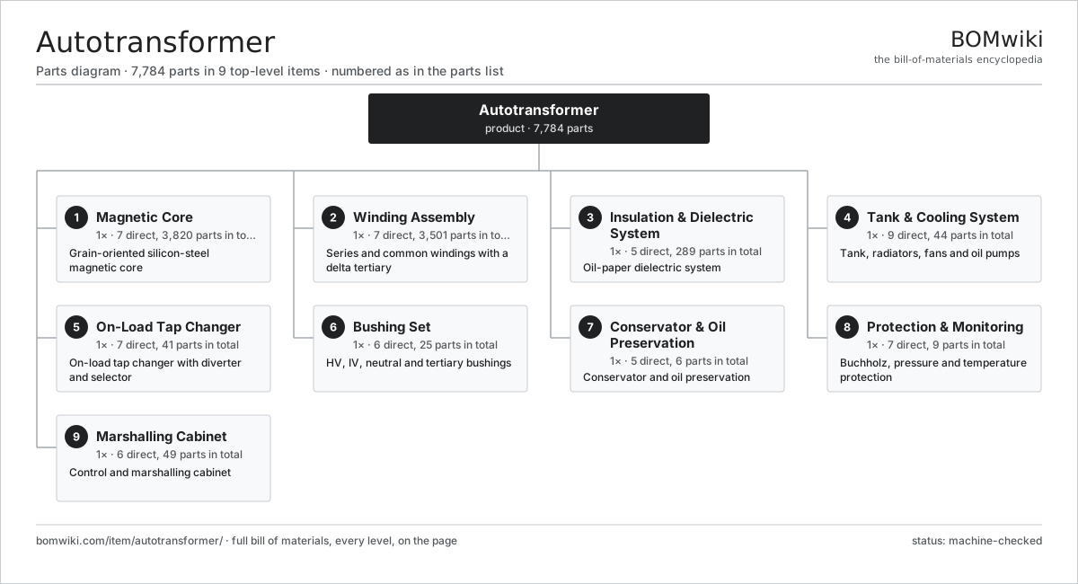
| # | Part | Qty | What it does |
|---|---|---|---|
| 1 | Magnetic Core 7 parts | 1× | Grain-oriented silicon-steel magnetic core |
| 2 | Winding Assembly 7 parts | 1× | Series and common windings with a delta tertiary |
| 3 | Insulation & Dielectric System 5 parts | 1× | Oil-paper dielectric system |
| 4 | Tank & Cooling System 9 parts | 1× | Tank, radiators, fans and oil pumps |
| 5 | On-Load Tap Changer 7 parts | 1× | On-load tap changer with diverter and selector |
| 6 | Bushing Set 6 parts | 1× | HV, IV, neutral and tertiary bushings |
| 7 | Conservator & Oil Preservation 5 parts | 1× | Conservator and oil preservation |
| 8 | Protection & Monitoring 7 parts | 1× | Buchholz, pressure and temperature protection |
| 9 | Marshalling Cabinet 6 parts | 1× | Control and marshalling cabinet |
3D model
No 3D model yet. Have a CAD file of this? Add a 3D model. STL renders right on this page; STEP, FreeCAD, and OpenSCAD sources are welcome too (openly licensed, like all 3D models on BOMwiki).
Build & assembly graph
expand / collapse · shared sub-assemblies converge · links to related products · est. labourTap an assembly to expand/collapse · tap a part to open it · use “Open page” for any node · drag to pan, scroll to zoom.
Bill of materials for Autotransformer
9 top-level lines · 82 rows shown · 7,784 parts total · indented to 3 levels| # | Item / sub-assembly | Part no. | Qty/assy | Ext. qty | Parts | Type |
|---|---|---|---|---|---|---|
| 1 | Magnetic Core 7 parts | autotransformer-core | 1× | 1 | 3,820 | assembly |
| 1.1 | GO Silicon-Steel Lamination | autotransformer-core-lamination | 3800× | 3,800 | · | part |
| 1.2 | Core Limb | autotransformer-core-limb | 3× | 3 | · | part |
| 1.3 | Core Yoke | autotransformer-core-yoke | 2× | 2 | · | part |
| 1.4 | Core Clamping Frame | autotransformer-clamping-frame | 2× | 2 | · | part |
| 1.5 | Core Tie Rod | autotransformer-core-tie-rod | 8× | 8 | · | part |
| 1.6 | Core Earthing Strap | autotransformer-core-ground-strap | 1× | 1 | · | part |
| 1.7 | Magnetic Flux Shunt | autotransformer-flux-shunt | 4× | 4 | · | part |
| 2 | Winding Assembly 7 parts | autotransformer-windings | 1× | 1 | 3,501 | assembly |
| 2.1 | Common Winding 3 parts | autotransformer-common-winding | 3× | 3 | 182 | assembly |
| 2.1.1 | Transposed Copper Conductor | autotransformer-ctc-conductor | 1× | 3 | · | part |
| 2.1.2 | Kraft Paper Insulation | autotransformer-paper-insulation | 1× | 3 | · | part |
| 2.1.3 | Pressboard Spacer | autotransformer-pressboard-spacer | 180× | 540 | · | part |
| 2.2 | Series Winding 4 parts | autotransformer-series-winding | 3× | 3 | 224 | assembly |
| 2.2.1 | Paper-Covered Copper Conductor | autotransformer-copper-conductor | 1× | 3 | · | part |
| 2.2.2 | Kraft Paper Insulation | autotransformer-paper-insulation | 1× | 3 | · | part |
| 2.2.3 | Electrostatic Static Ring | autotransformer-static-ring | 2× | 6 | · | part |
| 2.2.4 | Pressboard Spacer | autotransformer-pressboard-spacer | 220× | 660 | · | part |
| 2.3 | Delta Tertiary Winding 3 parts | autotransformer-tertiary-winding | 3× | 3 | 122 | assembly |
| 2.3.1 | Paper-Covered Copper Conductor | autotransformer-copper-conductor | 1× | 3 | · | part |
| 2.3.2 | Kraft Paper Insulation | autotransformer-paper-insulation | 1× | 3 | · | part |
| 2.3.3 | Pressboard Spacer | autotransformer-pressboard-spacer | 120× | 360 | · | part |
| 2.4 | Tap Winding | autotransformer-tap-winding | 3× | 3 | · | part |
| 2.5 | Pressboard Spacer | autotransformer-pressboard-spacer | 1900× | 1,900 | · | part |
| 2.6 | Barrier Cylinder | autotransformer-barrier-cylinder | 8× | 8 | · | part |
| 2.7 | Winding Clamping Ring | autotransformer-clamping-ring | 6× | 6 | · | part |
| 3 | Insulation & Dielectric System 5 parts | autotransformer-insulation | 1× | 1 | 289 | assembly |
| 3.1 | Mineral Insulating Oil | autotransformer-mineral-oil | 1× | 1 | · | part |
| 3.2 | Pressboard Angle Ring | autotransformer-angle-ring | 64× | 64 | · | part |
| 3.3 | Lead Snout | autotransformer-snout | 8× | 8 | · | part |
| 3.4 | Oil Duct Stick | autotransformer-duct-stick | 210× | 210 | · | part |
| 3.5 | End Insulation Block | autotransformer-end-block | 6× | 6 | · | part |
| 4 | Tank & Cooling System 9 parts | autotransformer-tank-cooling | 1× | 1 | 44 | assembly |
| 4.1 | Main Tank | autotransformer-main-tank | 1× | 1 | · | part |
| 4.2 | Tank Cover | autotransformer-tank-cover | 1× | 1 | · | part |
| 4.3 | Panel Radiator | autotransformer-radiator | 12× | 12 | · | part |
| 4.4 | Radiator Cooling Fan | autotransformer-cooling-fan | 16× | 16 | · | part |
| 4.5 | Oil Circulation Pump | autotransformer-oil-pump | 2× | 2 | · | part |
| 4.6 | Tank Valve | autotransformer-tank-valve | 8× | 8 | · | part |
| 4.7 | Oil Flow Indicator | autotransformer-flow-indicator | 2× | 2 | · | part |
| 4.8 | Fastener Set | fastener-set | 1× | 1 | · | part |
| 4.9 | O-Ring Set | oring-set | 1× | 1 | · | part |
| 5 | On-Load Tap Changer 7 parts | autotransformer-oltc | 1× | 1 | 41 | assembly |
| 5.1 | Diverter Switch | autotransformer-oltc-diverter | 1× | 1 | · | part |
| 5.2 | Tap Selector | autotransformer-oltc-selector | 1× | 1 | · | part |
| 5.3 | OLTC Motor Drive Unit 4 parts | autotransformer-oltc-motor-drive | 1× | 1 | 32 | assembly |
| 5.3.1 | Servo Motor 4 parts + deeper › | servo-motor | 1× | 1 | 24 | assembly |
| 5.3.2 | Drive Cam Shaft | autotransformer-oltc-cam | 1× | 1 | · | part |
| 5.3.3 | Relay | relay | 6× | 6 | · | part |
| 5.3.4 | Manual Operating Crank | autotransformer-oltc-hand-crank | 1× | 1 | · | part |
| 5.4 | Transition Resistor | autotransformer-oltc-transition-resistor | 4× | 4 | · | part |
| 5.5 | OLTC Oil Compartment | autotransformer-oltc-oil-compartment | 1× | 1 | · | part |
| 5.6 | Helical Gear Pair | gear-pair | 1× | 1 | · | part |
| 5.7 | Tap Position Counter | autotransformer-oltc-counter | 1× | 1 | · | part |
| 6 | Bushing Set 6 parts | autotransformer-bushings | 1× | 1 | 25 | assembly |
| 6.1 | HV Condenser Bushing | autotransformer-hv-bushing | 3× | 3 | · | part |
| 6.2 | IV Condenser Bushing | autotransformer-iv-bushing | 3× | 3 | · | part |
| 6.3 | Tertiary Bushing | autotransformer-tertiary-bushing | 3× | 3 | · | part |
| 6.4 | Neutral Bushing | autotransformer-neutral-bushing | 1× | 1 | · | part |
| 6.5 | Bushing Current Transformer | autotransformer-bushing-ct | 9× | 9 | · | part |
| 6.6 | Bushing Turret | autotransformer-bushing-turret | 6× | 6 | · | part |
| 7 | Conservator & Oil Preservation 5 parts | autotransformer-conservator | 1× | 1 | 6 | assembly |
| 7.1 | Conservator Tank | autotransformer-conservator-tank | 1× | 1 | · | part |
| 7.2 | Conservator Air-Cell | autotransformer-air-cell | 1× | 1 | · | part |
| 7.3 | Silica-Gel Breather | autotransformer-breather | 1× | 1 | · | part |
| 7.4 | Magnetic Oil Level Gauge | autotransformer-oil-gauge | 1× | 1 | · | part |
| 7.5 | Conservator Valve | autotransformer-conservator-valve | 2× | 2 | · | part |
| 8 | Protection & Monitoring 7 parts | autotransformer-protection | 1× | 1 | 9 | assembly |
| 8.1 | Buchholz Relay | autotransformer-buchholz-relay | 1× | 1 | · | part |
| 8.2 | Pressure Relief Device | autotransformer-pressure-relief | 2× | 2 | · | part |
| 8.3 | Sudden-Pressure Relay | autotransformer-sudden-pressure-relay | 1× | 1 | · | part |
| 8.4 | Winding Temperature Indicator | autotransformer-wti | 1× | 1 | · | part |
| 8.5 | Oil Temperature Indicator | autotransformer-oti | 1× | 1 | · | part |
| 8.6 | Pressure Sensor | pressure-sensor | 2× | 2 | · | part |
| 8.7 | Dissolved-Gas Monitor | autotransformer-dga-monitor | 1× | 1 | · | part |
| 9 | Marshalling Cabinet 6 parts | autotransformer-marshalling-cabinet | 1× | 1 | 49 | assembly |
| 9.1 | Sheet Metal Panel | sheet-panel | 6× | 6 | · | part |
| 9.2 | Cooler Control Unit | autotransformer-cooler-control | 1× | 1 | · | part |
| 9.3 | Relay | relay | 8× | 8 | · | part |
| 9.4 | Marshalling Terminal Block | autotransformer-terminal-block | 32× | 32 | · | part |
| 9.5 | Wire Bundle | wire-bundle | 1× | 1 | · | part |
| 9.6 | Cabinet Anti-Condensation Heater | autotransformer-cabinet-heater | 1× | 1 | · | part |
Related products
same domain, ranked by shared parts Combined Heat and Power Unit
522 parts · shares 17 with this page
Combined Heat and Power Unit
522 parts · shares 17 with this page
 Gas-Insulated Switchgear
281 parts · shares 17 with this page
Gas-Insulated Switchgear
281 parts · shares 17 with this page
 Large Power Transformer
1,844 parts · shares 17 with this page
Large Power Transformer
1,844 parts · shares 17 with this page
 Power Transformer
7,753 parts · shares 17 with this page
Power Transformer
7,753 parts · shares 17 with this page
 SCR NOx Reduction Unit
569 parts · shares 17 with this page
SCR NOx Reduction Unit
569 parts · shares 17 with this page
Sourcing: possible vendors
Browse the supplier directory → Prices, MOQ, and lead times are algorithmic estimates, not quotes, and not claims about these companies. Company mappings are curated by keyword; est. price band $5k–$50M. How estimates work| Vendor | HQ | Specialty | MOQ | Lead time |
|---|---|---|---|---|
| gevernova.com ↗ | Cambridge, US | Power generation | made to order | 20–40 wks |
| siemens-energy.com ↗ | Munich, DE | Power & grid | made to order | 20–40 wks |
| hitachienergy.com ↗ | Zurich, CH | Grid & transformers | made to order | 20–40 wks |
|
🇨🇭ABB
abb.com ↗
|
Zurich, CH | Electrification & automation | made to order | 20–40 wks |
| se.com ↗ | Rueil-Malmaison, FR | Electrical & automation | made to order | 20–40 wks |
898-word article