SCR NOx Reduction Unit
ProductOverview
A selective catalytic reduction unit removes nitrogen oxides (NO and NO2, together called NOx) from combustion exhaust by reacting them with ammonia over a solid catalyst. It sits downstream of a boiler, gas turbine, engine, or process heater and ahead of the stack. NOx forms when nitrogen and oxygen combine at flame temperatures, and it contributes to smog, acid rain, and respiratory harm, so emission permits cap it. The unit injects a metered ammonia stream into the flue gas, mixes the two, and passes the mixture through stacked catalyst layers held in the Catalyst Reactor Housing. Over the catalyst the ammonia reduces NOx to nitrogen and water. Removal of 80–95% is routine, taking inlet concentrations of 200–800 mg per Nm3 down to 20–100 mg per Nm3.
The reaction is selective because the ammonia reacts with NOx in preference to being oxidized by the surrounding oxygen, provided the gas stays inside the catalyst temperature window. That window is the central design constraint and shapes where the reactor is placed in the gas path.
Reaction chemistry
The main reactions consume ammonia and oxygen to convert NOx into harmless products. The dominant path with nitric oxide is:
4 NO + 4 NH3 + O2 -> 4 N2 + 6 H2O
A second path handles nitrogen dioxide, which makes up a smaller fraction of the inlet NOx:
2 NO2 + 4 NH3 + O2 -> 3 N2 + 6 H2O
A fast reaction runs when NO and NO2 arrive in equal amounts:
NO + NO2 + 2 NH3 -> 2 N2 + 3 H2O
The unit doses ammonia at a molar ratio of 0.8 to 1.0 against the measured NOx. Dosing below the ratio leaves NOx untreated; dosing above it pushes unreacted ammonia out of the reactor as ammonia slip. The Dosing Control System holds outlet NOx at the permit value while keeping slip inside the 2–5 ppm guarantee, since excess ammonia forms ammonium bisulfate that fouls downstream air heaters and adds to particulate.
Catalyst and reactor
The active material is usually vanadium pentoxide on a titania carrier, with tungsten or molybdenum oxides added to widen the temperature window and resist sulfur. For high-temperature service above 450 °C, zeolite catalyst is used instead. The catalyst comes as extruded Honeycomb Catalyst Element blocks with parallel channels, or as coated Plate Catalyst Element sheets that shed ash better in dirty gas. Elements pack into the Catalyst Modules, which crane into the reactor and rest on beam grids. Most reactors carry 2 to 4 active layers plus one empty layer, so operators can add catalyst as activity decays instead of replacing it all at once.
Performance depends on temperature. Below about 300 °C the reaction rate drops and ammonium salts condense on the catalyst; above about 400 °C the ammonia starts to oxidize and the catalyst can sinter. Gas residence is set by space velocity of 3,000 to 6,000 per hour, the ratio of volumetric gas flow to catalyst volume. Pressure drop across the layers runs 5 to 12 mbar, which the upstream fan must overcome. Catalyst lasts 24,000 to 40,000 hours before a layer is reloaded, with life cut short by arsenic, alkali metals, and fine ash that blind the pores.
Reagent supply
Ammonia reaches the reactor from the Reagent Storage and Dosing. Plants store either anhydrous ammonia, 19% aqueous ammonia, or 40% urea solution, with urea chosen where handling pure ammonia onsite is a hazard. Urea installations add a Urea Decomposition Chamber that hydrolyzes urea into ammonia, carbon dioxide, and water before injection. The reagent leaves a heated tank, passes through metering Dosing Pump units running on shared ball-bearing shafts, and joins a dilution air stream from a blower. Trace heating with a heating-element on the lines keeps urea above its 0 °C crystallization point. A pressure-sensor on the discharge confirms supply before the controller opens the injection valves.
Injection and mixing
The diluted ammonia enters the duct through the Ammonia Injection Grid, a pipe array spanning the cross section. Each lateral carries injection nozzles, and manual balancing valves trim flow to each zone so the ammonia profile matches the measured NOx profile. Even distribution matters because the catalyst cannot correct a maldistributed feed; a rich pocket slips ammonia while a lean pocket passes NOx. Downstream of the grid the Flow Straightening and Mixing uses a static mixer and turning vanes to blend the streams and flatten the velocity profile entering the reactor. Designers target an ammonia-to-NOx variation under 5% root mean square at the catalyst face.
Ash handling and cleaning
Coal and biomass exhaust carries fly ash that settles on the catalyst and plugs channels. The Sootblower System sweeps each layer with steam or compressed air on a timed cycle, and acoustic horns shake loose the fine fraction between sweeps. Ash that drops off the catalyst collects in the Ash Collection Hopper, where heated walls stop bridging and a rotary airlock meters the ash out while holding duct pressure. Gas-fired and engine applications carry far less ash and may omit sootblowers entirely.
Instrumentation and control
NOx analyzers at the Process Instrumentation inlet and outlet, an ammonia slip analyzer, an oxygen analyzer, and thermocouples across the layers feed the Dosing Control System. The controller runs a feedforward estimate from inlet NOx and gas flow, then trims it with feedback from the outlet analyzer. It locks out dosing when gas temperature falls below the catalyst window to prevent ammonium salt deposition, and it raises an alarm when slip climbs, which signals catalyst aging or a maldistributed grid. Relay outputs drive the pumps, valves, and blower, and the operator works from an HMI panel showing setpoints, trends, and alarms.
SCR NOx Reduction Unit parts and their functions
10 top-level parts · 569 parts in total · full bill of materials below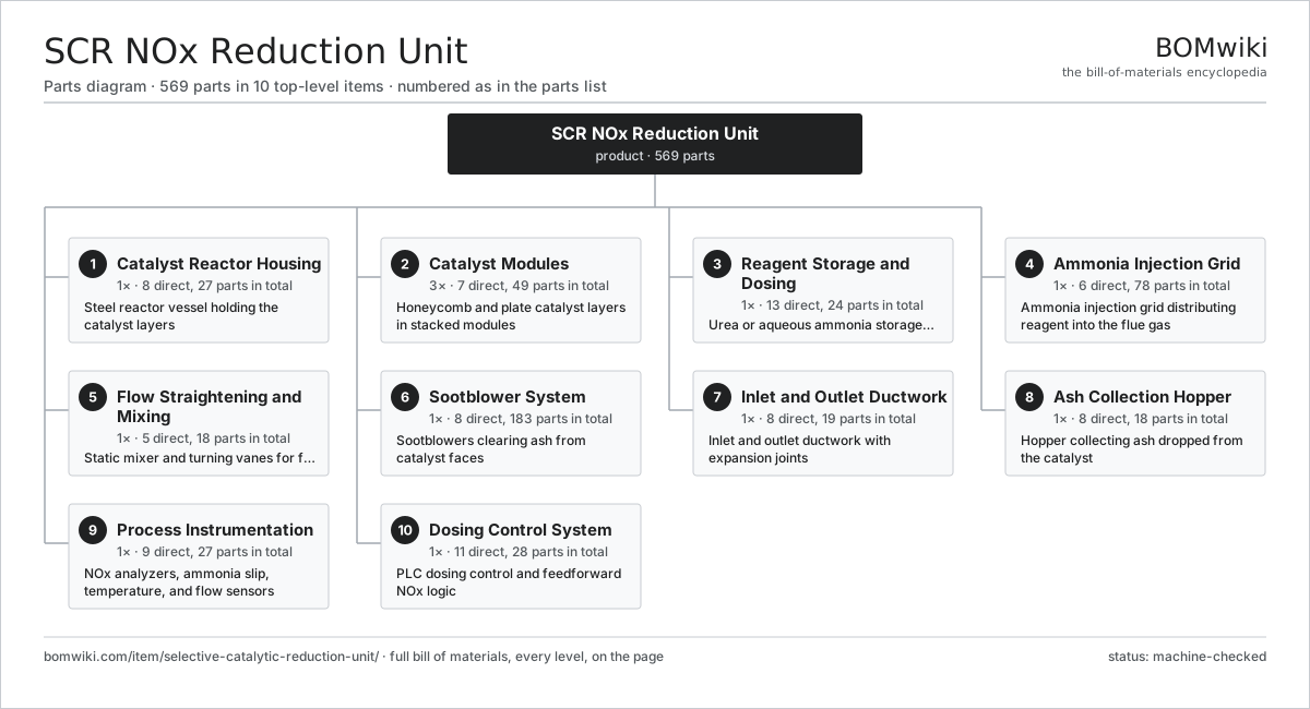
| # | Part | Qty | What it does |
|---|---|---|---|
| 1 | Catalyst Reactor Housing 8 parts | 1× | Steel reactor vessel holding the catalyst layers |
| 2 | Catalyst Modules 7 parts | 3× | Honeycomb and plate catalyst layers in stacked modules |
| 3 | Reagent Storage and Dosing 13 parts | 1× | Urea or aqueous ammonia storage, conversion, and dosing |
| 4 | Ammonia Injection Grid 6 parts | 1× | Ammonia injection grid distributing reagent into the flue gas |
| 5 | Flow Straightening and Mixing 5 parts | 1× | Static mixer and turning vanes for flow conditioning |
| 6 | Sootblower System 8 parts | 1× | Sootblowers clearing ash from catalyst faces |
| 7 | Inlet and Outlet Ductwork 8 parts | 1× | Inlet and outlet ductwork with expansion joints |
| 8 | Ash Collection Hopper 8 parts | 1× | Hopper collecting ash dropped from the catalyst |
| 9 | Process Instrumentation 9 parts | 1× | NOx analyzers, ammonia slip, temperature, and flow sensors |
| 10 | Dosing Control System 11 parts | 1× | PLC dosing control and feedforward NOx logic |
3D model
No 3D model yet. Have a CAD file of this? Add a 3D model. STL renders right on this page; STEP, FreeCAD, and OpenSCAD sources are welcome too (openly licensed, like all 3D models on BOMwiki).
Build & assembly graph
expand / collapse · shared sub-assemblies converge · links to related products · est. labourTap an assembly to expand/collapse · tap a part to open it · use “Open page” for any node · drag to pan, scroll to zoom.
Bill of materials for SCR NOx Reduction Unit
10 top-level lines · 97 rows shown · 569 parts total · indented to 3 levels| # | Item / sub-assembly | Part no. | Qty/assy | Ext. qty | Parts | Type |
|---|---|---|---|---|---|---|
| 1 | Catalyst Reactor Housing 8 parts | selective-catalytic-reduction-unit-reactor-housing | 1× | 1 | 27 | assembly |
| 1.1 | Reactor Shell | selective-catalytic-reduction-unit-housing-shell | 1× | 1 | · | part |
| 1.2 | Reactor Liner | selective-catalytic-reduction-unit-housing-liner | 1× | 1 | · | part |
| 1.3 | Catalyst Support Grid | selective-catalytic-reduction-unit-catalyst-support-grid | 3× | 3 | · | part |
| 1.4 | Module Seal Strip | selective-catalytic-reduction-unit-seal-strip | 12× | 12 | · | part |
| 1.5 | Access Door | selective-catalytic-reduction-unit-access-door | 2× | 2 | · | part |
| 1.6 | Flow Rectifier Plate | selective-catalytic-reduction-unit-flow-rectifier | 1× | 1 | · | part |
| 1.7 | Sheet Metal Panel | sheet-panel | 6× | 6 | · | part |
| 1.8 | Fastener Set | fastener-set | 1× | 1 | · | part |
| 2 | Catalyst Modules 7 parts | selective-catalytic-reduction-unit-catalyst-modules | 3× | 3 | 49 | assembly |
| 2.1 | Honeycomb Catalyst Element | selective-catalytic-reduction-unit-honeycomb-element | 16× | 48 | · | part |
| 2.2 | Plate Catalyst Element | selective-catalytic-reduction-unit-plate-element | 8× | 24 | · | part |
| 2.3 | Catalyst Module Frame | selective-catalytic-reduction-unit-module-frame | 4× | 12 | · | part |
| 2.4 | Module Gasket | selective-catalytic-reduction-unit-module-gasket | 8× | 24 | · | part |
| 2.5 | Module Lifting Lug | selective-catalytic-reduction-unit-lifting-lug | 8× | 24 | · | part |
| 2.6 | Cover Grating | selective-catalytic-reduction-unit-cover-grating | 4× | 12 | · | part |
| 2.7 | Fastener Set | fastener-set | 1× | 3 | · | part |
| 3 | Reagent Storage and Dosing 13 parts | selective-catalytic-reduction-unit-reagent-system | 1× | 1 | 24 | assembly |
| 3.1 | Reagent Storage Tank | selective-catalytic-reduction-unit-reagent-tank | 1× | 1 | · | part |
| 3.2 | Tank Heater | selective-catalytic-reduction-unit-tank-heater | 1× | 1 | · | part |
| 3.3 | Dosing Pump | selective-catalytic-reduction-unit-dosing-pump | 2× | 2 | · | part |
| 3.4 | Dosing Skid | selective-catalytic-reduction-unit-dosing-skid | 1× | 1 | · | part |
| 3.5 | Urea Decomposition Chamber | selective-catalytic-reduction-unit-decomposition-chamber | 1× | 1 | · | part |
| 3.6 | Dilution Air Blower | selective-catalytic-reduction-unit-dilution-blower | 1× | 1 | · | part |
| 3.7 | Reagent Mixing Lance | selective-catalytic-reduction-unit-mixing-lance | 4× | 4 | · | part |
| 3.8 | Flow Control Valve | selective-catalytic-reduction-unit-flow-control-valve | 2× | 2 | · | part |
| 3.9 | Pressure Sensor | pressure-sensor | 2× | 2 | · | part |
| 3.10 | Heating Element | heating-element | 2× | 2 | · | part |
| 3.11 | Ball Bearing | ball-bearing | 4× | 4 | · | part |
| 3.12 | Oil Seal | oil-seal | 2× | 2 | · | part |
| 3.13 | O-Ring Set | oring-set | 1× | 1 | · | part |
| 4 | Ammonia Injection Grid 6 parts | selective-catalytic-reduction-unit-injection-grid | 1× | 1 | 78 | assembly |
| 4.1 | Injection Grid Header | selective-catalytic-reduction-unit-aig-header | 1× | 1 | · | part |
| 4.2 | Injection Grid Lateral | selective-catalytic-reduction-unit-aig-lateral | 12× | 12 | · | part |
| 4.3 | Injection Nozzle | selective-catalytic-reduction-unit-aig-nozzle | 48× | 48 | · | part |
| 4.4 | Zone Balancing Valve | selective-catalytic-reduction-unit-aig-balancing-valve | 12× | 12 | · | part |
| 4.5 | Injection Grid Support | selective-catalytic-reduction-unit-aig-support | 4× | 4 | · | part |
| 4.6 | Fastener Set | fastener-set | 1× | 1 | · | part |
| 5 | Flow Straightening and Mixing 5 parts | selective-catalytic-reduction-unit-mixing-section | 1× | 1 | 18 | assembly |
| 5.1 | Static Mixer | selective-catalytic-reduction-unit-static-mixer | 1× | 1 | · | part |
| 5.2 | Turning Vane | selective-catalytic-reduction-unit-turning-vane | 8× | 8 | · | part |
| 5.3 | Flow Baffle | selective-catalytic-reduction-unit-flow-baffle | 4× | 4 | · | part |
| 5.4 | Vane Support | selective-catalytic-reduction-unit-vane-support | 4× | 4 | · | part |
| 5.5 | Fastener Set | fastener-set | 1× | 1 | · | part |
| 6 | Sootblower System 8 parts | selective-catalytic-reduction-unit-sootblower-system | 1× | 1 | 183 | assembly |
| 6.1 | Sootblower Lance | selective-catalytic-reduction-unit-sootblower-lance | 6× | 6 | · | part |
| 6.2 | Sootblower Drive | selective-catalytic-reduction-unit-sootblower-drive | 6× | 6 | · | part |
| 6.3 | Sootblower Supply Valve | selective-catalytic-reduction-unit-sootblower-valve | 6× | 6 | · | part |
| 6.4 | Acoustic Horn | selective-catalytic-reduction-unit-acoustic-horn | 2× | 2 | · | part |
| 6.5 | Helical Gear Pair | gear-pair | 6× | 6 | · | part |
| 6.6 | Servo Motor 4 parts | servo-motor | 6× | 6 | 24 | assembly |
| 6.6.1 | Stator Assembly 3 parts + deeper › | stator-assembly | 1× | 6 | 3 | assembly |
| 6.6.2 | Rotor Assembly 4 parts + deeper › | rotor-assembly | 1× | 6 | 19 | assembly |
| 6.6.3 | Encoder | encoder | 1× | 6 | · | part |
| 6.6.4 | Motor Housing | motor-housing | 1× | 6 | · | part |
| 6.7 | Ball Bearing | ball-bearing | 12× | 12 | · | part |
| 6.8 | Fastener Set | fastener-set | 1× | 1 | · | part |
| 7 | Inlet and Outlet Ductwork 8 parts | selective-catalytic-reduction-unit-ductwork | 1× | 1 | 19 | assembly |
| 7.1 | Inlet Transition Duct | selective-catalytic-reduction-unit-inlet-duct | 1× | 1 | · | part |
| 7.2 | Outlet Transition Duct | selective-catalytic-reduction-unit-outlet-duct | 1× | 1 | · | part |
| 7.3 | Expansion Joint | selective-catalytic-reduction-unit-expansion-joint | 4× | 4 | · | part |
| 7.4 | Bypass Damper | selective-catalytic-reduction-unit-bypass-damper | 1× | 1 | · | part |
| 7.5 | Isolation Damper | selective-catalytic-reduction-unit-isolation-damper | 2× | 2 | · | part |
| 7.6 | Duct Insulation | selective-catalytic-reduction-unit-duct-insulation | 1× | 1 | · | part |
| 7.7 | Sheet Metal Panel | sheet-panel | 8× | 8 | · | part |
| 7.8 | Fastener Set | fastener-set | 1× | 1 | · | part |
| 8 | Ash Collection Hopper 8 parts | selective-catalytic-reduction-unit-ash-hopper | 1× | 1 | 18 | assembly |
| 8.1 | Ash Hopper Body | selective-catalytic-reduction-unit-hopper-body | 2× | 2 | · | part |
| 8.2 | Hopper Heater | selective-catalytic-reduction-unit-hopper-heater | 2× | 2 | · | part |
| 8.3 | Rotary Airlock Valve | selective-catalytic-reduction-unit-rotary-valve | 2× | 2 | · | part |
| 8.4 | Hopper Level Probe | selective-catalytic-reduction-unit-level-probe | 2× | 2 | · | part |
| 8.5 | Helical Gear Pair | gear-pair | 2× | 2 | · | part |
| 8.6 | Ball Bearing | ball-bearing | 4× | 4 | · | part |
| 8.7 | Oil Seal | oil-seal | 2× | 2 | · | part |
| 8.8 | Heating Element | heating-element | 2× | 2 | · | part |
| 9 | Process Instrumentation 9 parts | selective-catalytic-reduction-unit-instrumentation | 1× | 1 | 27 | assembly |
| 9.1 | NOx Analyzer | selective-catalytic-reduction-unit-nox-analyzer | 2× | 2 | · | part |
| 9.2 | Ammonia Slip Analyzer | selective-catalytic-reduction-unit-ammonia-slip-analyzer | 1× | 1 | · | part |
| 9.3 | Oxygen Analyzer | selective-catalytic-reduction-unit-oxygen-analyzer | 1× | 1 | · | part |
| 9.4 | Catalyst Thermocouple | selective-catalytic-reduction-unit-thermocouple | 6× | 6 | · | part |
| 9.5 | Sampling Probe | selective-catalytic-reduction-unit-sampling-probe | 3× | 3 | · | part |
| 9.6 | Flow Element | selective-catalytic-reduction-unit-flow-element | 2× | 2 | · | part |
| 9.7 | Pressure Sensor | pressure-sensor | 3× | 3 | · | part |
| 9.8 | Wire Bundle | wire-bundle | 1× | 1 | · | part |
| 9.9 | Connector | connector | 8× | 8 | · | part |
| 10 | Dosing Control System 11 parts | selective-catalytic-reduction-unit-control-system | 1× | 1 | 28 | assembly |
| 10.1 | Dosing PLC | selective-catalytic-reduction-unit-plc | 1× | 1 | · | part |
| 10.2 | I/O Module | selective-catalytic-reduction-unit-io-module | 4× | 4 | · | part |
| 10.3 | HMI Panel | selective-catalytic-reduction-unit-hmi-panel | 1× | 1 | · | part |
| 10.4 | Bare PCB | pcb-bare | 2× | 2 | · | part |
| 10.5 | Microcontroller | mcu | 2× | 2 | · | part |
| 10.6 | SMD Passive (R/C/L) | smd-passives | 1× | 1 | · | part |
| 10.7 | Relay | relay | 8× | 8 | · | part |
| 10.8 | Power Supply | power-supply | 1× | 1 | · | part |
| 10.9 | LCD Panel | lcd-panel | 1× | 1 | · | part |
| 10.10 | Wire Bundle | wire-bundle | 1× | 1 | · | part |
| 10.11 | Connector | connector | 6× | 6 | · | part |
Related products
same domain, ranked by shared parts Gas-Insulated Switchgear
281 parts · shares 20 with this page
Gas-Insulated Switchgear
281 parts · shares 20 with this page
 Phase-Shifting Transformer
203 parts · shares 19 with this page
Phase-Shifting Transformer
203 parts · shares 19 with this page
 Coal Pulverizer Mill
313 parts · shares 19 with this page
Bottom Ash Handling System
1,782 parts · shares 20 with this page
Coal Pulverizer Mill
313 parts · shares 19 with this page
Bottom Ash Handling System
1,782 parts · shares 20 with this page
 Combined Heat and Power Unit
522 parts · shares 20 with this page
Combined Heat and Power Unit
522 parts · shares 20 with this page
 Air-Insulated Substation Bay
1,329 parts · shares 18 with this page
Air-Insulated Substation Bay
1,329 parts · shares 18 with this page
Sourcing: possible vendors
Browse the supplier directory → Prices, MOQ, and lead times are algorithmic estimates, not quotes, and not claims about these companies. Company mappings are curated by keyword; est. price band $5k–$50M. How estimates work| Vendor | HQ | Specialty | MOQ | Lead time |
|---|---|---|---|---|
| gevernova.com ↗ | Cambridge, US | Power generation | made to order | 20–40 wks |
| siemens-energy.com ↗ | Munich, DE | Power & grid | made to order | 20–40 wks |
| hitachienergy.com ↗ | Zurich, CH | Grid & transformers | made to order | 20–40 wks |
|
🇨🇭ABB
abb.com ↗
|
Zurich, CH | Electrification & automation | made to order | 20–40 wks |
| se.com ↗ | Rueil-Malmaison, FR | Electrical & automation | made to order | 20–40 wks |
991-word article