Busbar Trunking System
ProductAlso known as: bus duct, busway, busbar system, Busway/Busbar Trunking System
Overview
A busbar trunking system, also called bus duct, distributes power along a building using rigid metal conductors held inside a metal housing rather than cables in tray. It runs as a continuous spine from the supply, often a transformer or main panel, to loads spread across floors and bays. Power is drawn at any point through a Tap-off unit that plugs into openings in the housing. The system covered here is a sandwich type, where the bars are pressed close together with thin insulation between them, giving low reactance and a compact cross section.
A typical 30 m run is built from a End feed unit at the source, a series of straight and elbow lengths, and a closing End cover. Lengths are connected by bolted joints, supported by hangers and brackets, and broken at fire and movement points by barriers and an expansion joint.
Conductors and housing
Each Straight trunking length carries a Busbar Set of three phase bars and a neutral, plus a separate Earth bar. The bars are flat copper, sized for the rated current, and stacked with Bar insulation wrap between them: an epoxy powder coat on the bar followed by a Mylar film wrap. This sandwich arrangement keeps the loop area small, which lowers the voltage drop and the magnetic forces during a fault.
The bars sit inside a Trunking housing of folded steel that doubles as a low-impedance earth return and as mechanical protection. A Housing cover closes the assembly, and Insulating clamp block spacers along the length hold the bars on centre and resist the short-circuit forces quoted as the Icw rating. Openings in the side, each fitted with a Tap-off window, let tap-off boxes engage the bars without an electrician opening the live housing. An End plate closes each end of the length before it is jointed to the next. Where the route turns, a pre-formed Elbow length makes the bend with the bars already shaped.
Joints
Lengths are joined by a Bolted joint block. The sandwich design allows a single-bolt joint: one central Torque-indicating joint bolt draws two Joint pressure plate members together, clamping the silver-plated Silver-plated contact plate faces of both lengths into firm contact. The bolt is a torque-indicating shear head, so the installer tightens it until the head snaps at the correct torque, giving a visible record that the joint is sound.
Contact pressure is held over time by a stack of Belleville washer disc springs, which take up any relaxation as the bars heat and cool. A Joint insulation pad keeps the phases apart inside the joint, and a snap-on Joint cover shroud shrouds the assembly to restore the housing rating once the joint is made.
Tap-off units
Loads are fed from the run through tap-off units. A Tap-off unit is a sheet steel box that hangs on the housing and plugs into a tap-off window. Inside, a set of Sprung tap contact sprung contacts grip the phase and neutral bars, while a leading Tap-off earth contact makes earth first and breaks it last for safety. A Auto contact shutter covers the bars when the box is removed, so the open window is not live to the touch.
Each box contains an Moulded-case circuit breaker moulded-case circuit breaker to protect the outgoing circuit, mounted on a DIN rail and wired through a Terminal block to the outgoing cables. Cables leave through a Cable gland in the gland plate. A Door interlock stops the Tap-off door opening while the breaker is closed, and prevents the box being unplugged under load.
Installation
The run is hung from the structure with a Support hanger set at the spacing given by the maker, usually every 1.5 to 2 m, and fixed to walls with a Wall bracket where needed. On long or vertical runs a Expansion joint with flexible copper links absorbs the movement caused by thermal cycling, so the joints are not stressed.
Where the duct passes through a fire-rated floor or wall it is fitted with a Fire barrier, an intumescent assembly that seals the penetration and stops fire and smoke tracking along the housing. After assembly the run is labelled with a Phase and earth marker set for phase rotation, neutral and earth, then insulation-resistance and continuity tested before energising. Because the bars are factory built and the joints are bolted to a set torque, commissioning is faster than terminating an equivalent run of large single-core cables, and adding a load later is a matter of plugging in a new tap-off box at the nearest window.
Busbar Trunking System parts and their functions
11 top-level parts · 915 parts in total · full bill of materials below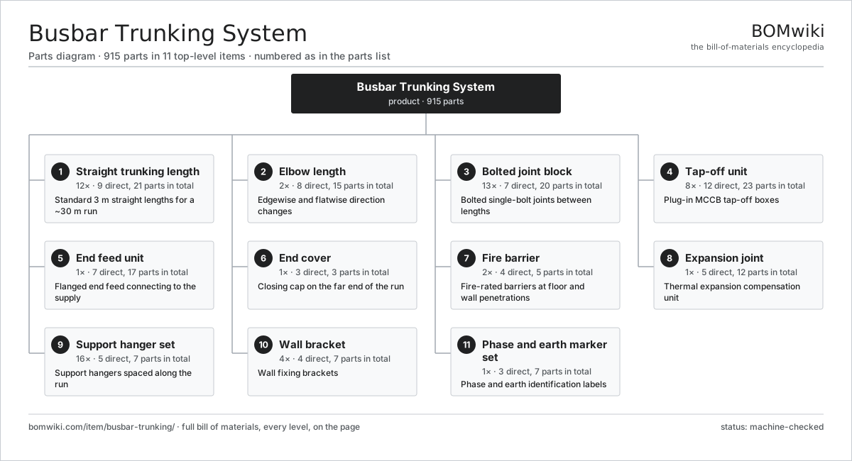
| # | Part | Qty | What it does |
|---|---|---|---|
| 1 | Straight trunking length 9 parts | 12× | Standard 3 m straight lengths for a ~30 m run |
| 2 | Elbow length 8 parts | 2× | Edgewise and flatwise direction changes |
| 3 | Bolted joint block 7 parts | 13× | Bolted single-bolt joints between lengths |
| 4 | Tap-off unit 12 parts | 8× | Plug-in MCCB tap-off boxes |
| 5 | End feed unit 7 parts | 1× | Flanged end feed connecting to the supply |
| 6 | End cover 3 parts | 1× | Closing cap on the far end of the run |
| 7 | Fire barrier 4 parts | 2× | Fire-rated barriers at floor and wall penetrations |
| 8 | Expansion joint 5 parts | 1× | Thermal expansion compensation unit |
| 9 | Support hanger set 5 parts | 16× | Support hangers spaced along the run |
| 10 | Wall bracket 4 parts | 4× | Wall fixing brackets |
| 11 | Phase and earth marker set 3 parts | 1× | Phase and earth identification labels |
Diagrams & photos


3D model
No 3D model yet. Have a CAD file of this? Add a 3D model. STL renders right on this page; STEP, FreeCAD, and OpenSCAD sources are welcome too (openly licensed, like all 3D models on BOMwiki).
Build & assembly graph
expand / collapse · shared sub-assemblies converge · links to related products · est. labourTap an assembly to expand/collapse · tap a part to open it · use “Open page” for any node · drag to pan, scroll to zoom.
Bill of materials for Busbar Trunking System
11 top-level lines · 78 rows shown · 915 parts total · indented to 3 levels| # | Item / sub-assembly | Part no. | Qty/assy | Ext. qty | Parts | Type |
|---|---|---|---|---|---|---|
| 1 | Straight trunking length 9 parts | bt-straight-length | 12× | 12 | 21 | assembly |
| 1.1 | Busbar Set | busbar-set | 1× | 12 | · | part |
| 1.2 | Earth bar | bt-earth-bar | 1× | 12 | · | part |
| 1.3 | Bar insulation wrap | bt-bar-insulation | 4× | 48 | · | part |
| 1.4 | Trunking housing | bt-housing | 1× | 12 | · | part |
| 1.5 | Housing cover | bt-housing-cover | 1× | 12 | · | part |
| 1.6 | Tap-off window | bt-tap-off-window | 4× | 48 | · | part |
| 1.7 | Insulating clamp block | bt-clamp-block | 6× | 72 | · | part |
| 1.8 | Fastener Set | fastener-set | 1× | 12 | · | part |
| 1.9 | End plate | bt-end-plate | 2× | 24 | · | part |
| 2 | Elbow length 8 parts | bt-elbow-length | 2× | 2 | 15 | assembly |
| 2.1 | Busbar Set | busbar-set | 1× | 2 | · | part |
| 2.2 | Earth bar | bt-earth-bar | 1× | 2 | · | part |
| 2.3 | Bar insulation wrap | bt-bar-insulation | 4× | 8 | · | part |
| 2.4 | Trunking housing | bt-housing | 1× | 2 | · | part |
| 2.5 | Housing cover | bt-housing-cover | 1× | 2 | · | part |
| 2.6 | Insulating clamp block | bt-clamp-block | 4× | 8 | · | part |
| 2.7 | Fastener Set | fastener-set | 1× | 2 | · | part |
| 2.8 | End plate | bt-end-plate | 2× | 4 | · | part |
| 3 | Bolted joint block 7 parts | bt-joint-block | 13× | 13 | 20 | assembly |
| 3.1 | Torque-indicating joint bolt | bt-joint-bolt | 1× | 13 | · | part |
| 3.2 | Belleville washer | bt-belleville-washer | 4× | 52 | · | part |
| 3.3 | Joint pressure plate | bt-joint-pressure-plate | 2× | 26 | · | part |
| 3.4 | Joint insulation pad | bt-joint-insulation-pad | 2× | 26 | · | part |
| 3.5 | Silver-plated contact plate | bt-contact-plate | 8× | 104 | · | part |
| 3.6 | Joint cover shroud | bt-joint-cover | 2× | 26 | · | part |
| 3.7 | Fastener Set | fastener-set | 1× | 13 | · | part |
| 4 | Tap-off unit 12 parts | bt-tap-off-unit | 8× | 8 | 23 | assembly |
| 4.1 | Tap-off enclosure | bt-tap-off-enclosure | 1× | 8 | · | part |
| 4.2 | Tap-off door | bt-tap-off-door | 1× | 8 | · | part |
| 4.3 | Sprung tap contact | bt-tap-off-contact-set | 4× | 32 | · | part |
| 4.4 | Tap-off earth contact | bt-tap-off-earth-contact | 1× | 8 | · | part |
| 4.5 | Moulded-case circuit breaker | bt-mccb | 1× | 8 | · | part |
| 4.6 | Door interlock | bt-tap-off-interlock | 1× | 8 | · | part |
| 4.7 | Auto contact shutter | bt-tap-off-shutter | 1× | 8 | · | part |
| 4.8 | Cable gland plate | bt-cable-gland-plate | 1× | 8 | · | part |
| 4.9 | Cable gland | bt-cable-gland | 4× | 32 | · | part |
| 4.10 | DIN rail | bt-din-rail | 1× | 8 | · | part |
| 4.11 | Terminal block | bt-terminal-block | 6× | 48 | · | part |
| 4.12 | Fastener Set | fastener-set | 1× | 8 | · | part |
| 5 | End feed unit 7 parts | bt-end-feed-unit | 1× | 1 | 17 | assembly |
| 5.1 | End feed box | bt-end-feed-box | 1× | 1 | · | part |
| 5.2 | Feed terminal pad | bt-feed-terminal | 4× | 4 | · | part |
| 5.3 | Cable gland plate | bt-cable-gland-plate | 1× | 1 | · | part |
| 5.4 | Cable gland | bt-cable-gland | 8× | 8 | · | part |
| 5.5 | End feed cover | bt-end-feed-cover | 1× | 1 | · | part |
| 5.6 | Feed earth bar | bt-feed-earth-bar | 1× | 1 | · | part |
| 5.7 | Fastener Set | fastener-set | 1× | 1 | · | part |
| 6 | End cover 3 parts | bt-end-cover | 1× | 1 | 3 | assembly |
| 6.1 | End cap | bt-end-cap | 1× | 1 | · | part |
| 6.2 | End cap insulation | bt-end-cap-insulation | 1× | 1 | · | part |
| 6.3 | Fastener Set | fastener-set | 1× | 1 | · | part |
| 7 | Fire barrier 4 parts | bt-fire-barrier | 2× | 2 | 5 | assembly |
| 7.1 | Fire barrier board | bt-fire-barrier-board | 2× | 4 | · | part |
| 7.2 | Fire barrier sleeve | bt-fire-barrier-sleeve | 1× | 2 | · | part |
| 7.3 | Intumescent mastic | bt-fire-mastic | 1× | 2 | · | part |
| 7.4 | Fastener Set | fastener-set | 1× | 2 | · | part |
| 8 | Expansion joint 5 parts | bt-expansion-joint | 1× | 1 | 12 | assembly |
| 8.1 | Flexible expansion link | bt-flexible-link | 4× | 4 | · | part |
| 8.2 | Expansion housing | bt-expansion-housing | 1× | 1 | · | part |
| 8.3 | PTFE slide guide | bt-slide-guide | 2× | 2 | · | part |
| 8.4 | Bar insulation wrap | bt-bar-insulation | 4× | 4 | · | part |
| 8.5 | Fastener Set | fastener-set | 1× | 1 | · | part |
| 9 | Support hanger set 5 parts | bt-hanger-set | 16× | 16 | 7 | assembly |
| 9.1 | Hanger cradle | bt-hanger-cradle | 1× | 16 | · | part |
| 9.2 | Threaded rod | bt-threaded-rod | 2× | 32 | · | part |
| 9.3 | Channel spring nut | bt-spring-nut | 2× | 32 | · | part |
| 9.4 | Rubber isolator pad | bt-rubber-isolator | 1× | 16 | · | part |
| 9.5 | Fastener Set | fastener-set | 1× | 16 | · | part |
| 10 | Wall bracket 4 parts | bt-wall-bracket | 4× | 4 | 7 | assembly |
| 10.1 | Bracket arm | bt-bracket-arm | 1× | 4 | · | part |
| 10.2 | Bracket base | bt-bracket-base | 1× | 4 | · | part |
| 10.3 | Anchor bolt | bt-anchor-bolt | 4× | 16 | · | part |
| 10.4 | Fastener Set | fastener-set | 1× | 4 | · | part |
| 11 | Phase and earth marker set 3 parts | bt-phase-marker-set | 1× | 1 | 7 | assembly |
| 11.1 | Phase label | bt-phase-label | 4× | 4 | · | part |
| 11.2 | Earth label | bt-earth-label | 1× | 1 | · | part |
| 11.3 | Warning label | bt-warning-label | 2× | 2 | · | part |
Sourcing: possible vendors
Browse the supplier directory → Prices, MOQ, and lead times are algorithmic estimates, not quotes, and not claims about these companies. Company mappings are curated by keyword; est. price band $5k–$50M. How estimates work| Vendor | HQ | Specialty | MOQ | Lead time |
|---|---|---|---|---|
| gevernova.com ↗ | Cambridge, US | Power generation | made to order | 20–40 wks |
| siemens-energy.com ↗ | Munich, DE | Power & grid | made to order | 20–40 wks |
| hitachienergy.com ↗ | Zurich, CH | Grid & transformers | made to order | 20–40 wks |
|
🇨🇭ABB
abb.com ↗
|
Zurich, CH | Electrification & automation | made to order | 20–40 wks |
| se.com ↗ | Rueil-Malmaison, FR | Electrical & automation | made to order | 20–40 wks |
804-word article