Bottom Ash Handling System
ProductOverview
A Bottom Ash Handling System removes the heavy ash and clinker that falls through the furnace throat of a coal-fired boiler. In a pulverised-coal unit roughly 15 to 20 percent of the total ash drops out of the bottom of the furnace as bottom ash, while the rest leaves with the flue gas as fly ash. The bottom ash arrives molten or near-molten at temperatures above 1000 C, often as large fused clinkers, and it must be quenched, broken, transported and dewatered before it can be trucked away. This system does that job continuously beneath the boiler.
The wet, water-impounded arrangement described here is the common design for large utility boilers. The boiler sits over a water-filled Water-Impounded Bottom Ash Hopper whose water both quenches the falling ash and forms a gas seal at the furnace throat. A Submerged Scraper Conveyor drags the cooled ash out of the water and up an incline to discharge, where Clinker Grinder units crush oversize lumps and a Hydraulic Sluice System carries the broken ash as a slurry to a Dewatering Bin.
How it works
Ash and clinker fall continuously from the furnace into the Water-Impounded Bottom Ash Hopper. The hopper holds a standing water level maintained by Makeup Water Valve units, with a Water Seal Trough around the throat that keeps furnace gases from escaping into the ash-handling area. Quench Spray Nozzle sprays cool the incoming ash so the hopper water stays around 60-70 C. The thermal shock from quenching shatters much of the clinker into smaller pieces.
The submerged scraper conveyor runs along the bottom of the hopper. A Drag Chain Strand fitted with Scraper Flight Bar scrapers drags settled ash along the Conveyor Trough, up the Incline Casing Section, and out of the water. The incline acts as a dewatering ramp: as the ash climbs the 30-35 degree slope it drains, so it leaves the conveyor with most of the free water shed. Chain speed is low, typically 1.5 to 4 m/min, set by the Conveyor Gearmotor through a variable frequency drive so the rate can be matched to the boiler load.
At the conveyor head the ash drops into the Clinker Grinder. Two toothed Grinder Roll crushers reduce clinker to under 25 mm, small enough for the sluice to carry without blocking. A Shear-Pin Coupling protects the grinder drive if a piece of tramp metal jams the rolls. The crushed ash then enters the Hydraulic Sluice System, where Eductor Jet Pump eductors use high-pressure water to entrain the ash and push it through Sluice Pipe runs to the dewatering bin.
In the Dewatering Bin the slurry slows and the ash settles. Clarified water is drawn off through Telescopic Decant Pipe tubes and returned to the system by the Ash Transfer Pump Station, while the settled ash collects in the Underflow Cone and is released through a Bin Discharge Gate into trucks below. Recirculating the decant water keeps fresh-water makeup low.
Subsystems
The hopper, conveyor, grinder, sluice, dewatering bin, pump station, support steel and control panel each handle one stage of the path from furnace to truck. The Ash Transfer Pump Station uses rubber-lined Slurry Pump units, one duty and one standby, each rated around 90 kW and 300 m3/h, with high-chrome Pump Impeller wheels chosen to survive the abrasive flow. A Seal Water Skid supplies clean gland flush so the Mechanical Seal does not run on gritty water.
The Structural Support Steel frame carries the hopper, the conveyor incline and the bin under the boiler, with Access Platform levels and Stair Flight runs for maintenance access. The Control Panel sequences everything: a PLC Rack reads Pressure Sensor and level signals, drives the Variable Frequency Drive units feeding the motors, and runs interlocks through a Motor Control Center Section so the conveyor cannot start with the hopper water low.
Materials and construction
The ash path is highly abrasive, so wear materials appear throughout. The hopper carries a Refractory Lining of high-alumina castable, 75 mm thick, against the heat and thermal shock at the throat. The conveyor trough floor uses bolt-in Trough Wear Liner plates of abrasion-resistant steel, and the Drag Chain Strand is forged and heat-treated for a breaking load near 200 kN. Grinder rolls run replaceable hardfaced Grinder Tooth Ring segments and Ni-hard Grinder Wear Liner plates. Sluice lines are basalt-lined steel pipe, and the wear-prone elbows use ceramic-faced Sluice Wear-Back Bend sections with a thick wear back. Shafts such as the Conveyor Headshaft are forged 42CrMo4 running in sealed Ball Bearing units protected by Oil Seal sets.
Variants
Plants that want a drier ash product or that have limited water use a dry bottom ash system instead, where a steel-belt conveyor carries ash through an air-cooled enclosure with no quench water. A pneumatic variant uses vacuum or pressure conveying through pipework rather than a wet sluice. Older plants often used a jet-pulse hopper that stored a batch of ash under water and sluiced it out on a timed cycle, but continuous submerged scraper conveyors have largely replaced that batch approach on new units because they avoid the load swings of cyclic sluicing.
Operation and use
In normal running the system is fully automatic. The PLC holds the conveyor at a steady low speed, matches the Clinker Grinder and Slurry Pump to the ash load, and tops up the hopper water seal as it evaporates. Operators watch the HMI Touchscreen for drive currents, water levels and any high-temperature alarm at the throat. The decant loop is checked so the dewatering bin water stays clear enough to recirculate.
Common failures
Chain wear and stretch is the most common maintenance item: a worn Drag Chain Strand rides high on the Drive Sprocket and skips teeth, so the Chain Tensioner take-up is adjusted on a schedule and the chain is replaced when stretch exceeds about 3 percent. Grinder tooth rings wear flat and stop sizing clinker properly, which then blocks the sluice. Slurry pump impellers and casing liners erode and lose head over time. Sluice elbows wear through at the back of the bend if the ceramic facing is missed during inspection. Loss of the hopper water seal, from a stuck Makeup Water Valve or a blocked Overflow Weir Box, lets furnace gas into the ash area and trips the unit on the throat temperature interlock.
Bottom Ash Handling System parts and their functions
8 top-level parts · 1,782 parts in total · full bill of materials below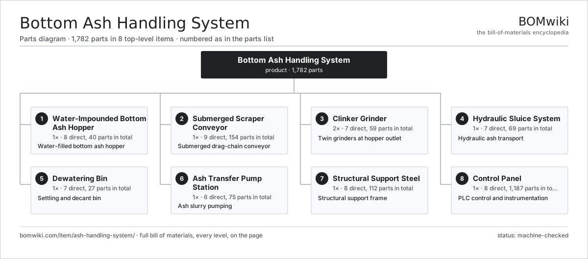
| # | Part | Qty | What it does |
|---|---|---|---|
| 1 | Water-Impounded Bottom Ash Hopper 8 parts | 1× | Water-filled bottom ash hopper |
| 2 | Submerged Scraper Conveyor 9 parts | 1× | Submerged drag-chain conveyor |
| 3 | Clinker Grinder 7 parts | 2× | Twin grinders at hopper outlet |
| 4 | Hydraulic Sluice System 7 parts | 1× | Hydraulic ash transport |
| 5 | Dewatering Bin 7 parts | 1× | Settling and decant bin |
| 6 | Ash Transfer Pump Station 6 parts | 1× | Ash slurry pumping |
| 7 | Structural Support Steel 8 parts | 1× | Structural support frame |
| 8 | Control Panel 8 parts | 1× | PLC control and instrumentation |
3D model
No 3D model yet. Have a CAD file of this? Add a 3D model. STL renders right on this page; STEP, FreeCAD, and OpenSCAD sources are welcome too (openly licensed, like all 3D models on BOMwiki).
Build & assembly graph
expand / collapse · shared sub-assemblies converge · links to related products · est. labourTap an assembly to expand/collapse · tap a part to open it · use “Open page” for any node · drag to pan, scroll to zoom.
Bill of materials for Bottom Ash Handling System
8 top-level lines · 156 rows shown · 1,782 parts total · indented to 3 levels| # | Item / sub-assembly | Part no. | Qty/assy | Ext. qty | Parts | Type |
|---|---|---|---|---|---|---|
| 1 | Water-Impounded Bottom Ash Hopper 8 parts | ash-handling-system-impounded-hopper | 1× | 1 | 40 | assembly |
| 1.1 | Hopper Shell 4 parts | ash-handling-system-hopper-shell | 1× | 1 | 11 | assembly |
| 1.1.1 | Hopper Plate | ash-handling-system-hopper-plate | 1× | 1 | · | part |
| 1.1.2 | Hopper Stiffener Rib | ash-handling-system-hopper-stiffener | 8× | 8 | · | part |
| 1.1.3 | Furnace Throat Flange | ash-handling-system-throat-flange | 1× | 1 | · | part |
| 1.1.4 | Fastener Set | fastener-set | 1× | 1 | · | part |
| 1.2 | Refractory Lining | ash-handling-system-refractory-lining | 1× | 1 | · | part |
| 1.3 | Water Seal Trough 3 parts | ash-handling-system-water-seal-trough | 1× | 1 | 3 | assembly |
| 1.3.1 | Seal Trough Plate | ash-handling-system-seal-trough-plate | 1× | 1 | · | part |
| 1.3.2 | Furnace Seal Skirt | ash-handling-system-seal-skirt | 1× | 1 | · | part |
| 1.3.3 | O-Ring Set | oring-set | 1× | 1 | · | part |
| 1.4 | Quench Spray Nozzle | ash-handling-system-quench-nozzle | 12× | 12 | · | part |
| 1.5 | Overflow Weir Box | ash-handling-system-overflow-weir | 1× | 1 | · | part |
| 1.6 | Hopper Knife Gate 4 parts | ash-handling-system-hopper-gate | 2× | 2 | 4 | assembly |
| 1.6.1 | Knife Gate Blade | ash-handling-system-gate-blade | 1× | 2 | · | part |
| 1.6.2 | Knife Gate Body | ash-handling-system-gate-body | 1× | 2 | · | part |
| 1.6.3 | Hydraulic Cylinder | ash-handling-system-hydraulic-cylinder | 1× | 2 | · | part |
| 1.6.4 | O-Ring Set | oring-set | 1× | 2 | · | part |
| 1.7 | Makeup Water Valve | ash-handling-system-makeup-water-valve | 2× | 2 | · | part |
| 1.8 | Pressure Sensor | pressure-sensor | 2× | 2 | · | part |
| 2 | Submerged Scraper Conveyor 9 parts | ash-handling-system-scraper-conveyor | 1× | 1 | 154 | assembly |
| 2.1 | Conveyor Trough 4 parts | ash-handling-system-conveyor-trough | 1× | 1 | 16 | assembly |
| 2.1.1 | Trough Section | ash-handling-system-trough-section | 6× | 6 | · | part |
| 2.1.2 | Incline Casing Section | ash-handling-system-incline-section | 1× | 1 | · | part |
| 2.1.3 | Trough Cover Plate | ash-handling-system-trough-cover | 8× | 8 | · | part |
| 2.1.4 | Fastener Set | fastener-set | 1× | 1 | · | part |
| 2.2 | Drag Chain Strand | ash-handling-system-drag-chain | 2× | 2 | · | part |
| 2.3 | Scraper Flight Bar | ash-handling-system-flight-bar | 60× | 60 | · | part |
| 2.4 | Drive Sprocket 4 parts | ash-handling-system-drive-sprocket | 2× | 2 | 6 | assembly |
| 2.4.1 | Sprocket Rim | ash-handling-system-sprocket-rim | 1× | 2 | · | part |
| 2.4.2 | Conveyor Headshaft | ash-handling-system-headshaft | 1× | 2 | · | part |
| 2.4.3 | Ball Bearing | ball-bearing | 2× | 4 | · | part |
| 2.4.4 | Oil Seal | oil-seal | 2× | 4 | · | part |
| 2.5 | Tail Sprocket 4 parts | ash-handling-system-tail-sprocket | 2× | 2 | 6 | assembly |
| 2.5.1 | Sprocket Rim | ash-handling-system-sprocket-rim | 1× | 2 | · | part |
| 2.5.2 | Conveyor Tailshaft | ash-handling-system-tailshaft | 1× | 2 | · | part |
| 2.5.3 | Ball Bearing | ball-bearing | 2× | 4 | · | part |
| 2.5.4 | Oil Seal | oil-seal | 2× | 4 | · | part |
| 2.6 | Conveyor Gearmotor 6 parts | ash-handling-system-conveyor-gearmotor | 1× | 1 | 35 | assembly |
| 2.6.1 | Servo Motor 4 parts + deeper › | servo-motor | 1× | 1 | 24 | assembly |
| 2.6.2 | Helical Gear Pair | gear-pair | 2× | 2 | · | part |
| 2.6.3 | Gearbox Housing | gearbox-housing | 1× | 1 | · | part |
| 2.6.4 | Ball Bearing | ball-bearing | 4× | 4 | · | part |
| 2.6.5 | Oil Seal | oil-seal | 3× | 3 | · | part |
| 2.6.6 | Anti-Runback Backstop | ash-handling-system-backstop | 1× | 1 | · | part |
| 2.7 | Chain Tensioner 3 parts | ash-handling-system-chain-tensioner | 2× | 2 | 4 | assembly |
| 2.7.1 | Take-Up Screw | ash-handling-system-takeup-screw | 1× | 2 | · | part |
| 2.7.2 | Take-Up Frame | ash-handling-system-takeup-frame | 1× | 2 | · | part |
| 2.7.3 | Coil Spring | coil-spring | 2× | 4 | · | part |
| 2.8 | Trough Wear Liner | ash-handling-system-wear-liner | 8× | 8 | · | part |
| 2.9 | Trough Water Valve | ash-handling-system-trough-water-valve | 1× | 1 | · | part |
| 3 | Clinker Grinder 7 parts | ash-handling-system-clinker-grinder | 2× | 2 | 59 | assembly |
| 3.1 | Grinder Housing | ash-handling-system-grinder-housing | 1× | 2 | · | part |
| 3.2 | Grinder Roll 3 parts | ash-handling-system-grinder-roll | 2× | 4 | 6 | assembly |
| 3.2.1 | Roll Shaft | ash-handling-system-roll-shaft | 1× | 4 | · | part |
| 3.2.2 | Grinder Tooth Ring | ash-handling-system-grinder-tooth-ring | 4× | 16 | · | part |
| 3.2.3 | Fastener Set | fastener-set | 1× | 4 | · | part |
| 3.3 | Grinder Gearmotor 5 parts | ash-handling-system-grinder-gearmotor | 1× | 2 | 33 | assembly |
| 3.3.1 | Servo Motor 4 parts + deeper › | servo-motor | 1× | 2 | 24 | assembly |
| 3.3.2 | Helical Gear Pair | gear-pair | 2× | 4 | · | part |
| 3.3.3 | Gearbox Housing | gearbox-housing | 1× | 2 | · | part |
| 3.3.4 | Ball Bearing | ball-bearing | 4× | 8 | · | part |
| 3.3.5 | Oil Seal | oil-seal | 2× | 4 | · | part |
| 3.4 | Shear-Pin Coupling | ash-handling-system-shear-pin-coupling | 1× | 2 | · | part |
| 3.5 | Ball Bearing | ball-bearing | 4× | 8 | · | part |
| 3.6 | Oil Seal | oil-seal | 4× | 8 | · | part |
| 3.7 | Grinder Wear Liner | ash-handling-system-grinder-liner | 4× | 8 | · | part |
| 4 | Hydraulic Sluice System 7 parts | ash-handling-system-sluice-system | 1× | 1 | 69 | assembly |
| 4.1 | Eductor Jet Pump 4 parts | ash-handling-system-jet-pump | 2× | 2 | 4 | assembly |
| 4.1.1 | Jet Nozzle | ash-handling-system-jet-nozzle | 1× | 2 | · | part |
| 4.1.2 | Jet Throat Liner | ash-handling-system-jet-throat | 1× | 2 | · | part |
| 4.1.3 | Jet Pump Body | ash-handling-system-jet-body | 1× | 2 | · | part |
| 4.1.4 | O-Ring Set | oring-set | 1× | 2 | · | part |
| 4.2 | Sluice Pipe | ash-handling-system-sluice-pipe | 12× | 12 | · | part |
| 4.3 | Sluice Wear-Back Bend | ash-handling-system-sluice-bend | 8× | 8 | · | part |
| 4.4 | Flushing Nozzle | ash-handling-system-flushing-nozzle | 16× | 16 | · | part |
| 4.5 | Slurry Isolation Valve 3 parts | ash-handling-system-isolation-valve | 6× | 6 | 3 | assembly |
| 4.5.1 | Pinch Valve Sleeve | ash-handling-system-pinch-sleeve | 1× | 6 | · | part |
| 4.5.2 | Pinch Valve Body | ash-handling-system-valve-body | 1× | 6 | · | part |
| 4.5.3 | Hydraulic Cylinder | ash-handling-system-hydraulic-cylinder | 1× | 6 | · | part |
| 4.6 | Sluice Trough | ash-handling-system-sluice-trough | 4× | 4 | · | part |
| 4.7 | Pressure Sensor | pressure-sensor | 3× | 3 | · | part |
| 5 | Dewatering Bin 7 parts | ash-handling-system-dewatering-bin | 1× | 1 | 27 | assembly |
| 5.1 | Bin Shell 4 parts | ash-handling-system-bin-shell | 1× | 1 | 14 | assembly |
| 5.1.1 | Bin Plate | ash-handling-system-bin-plate | 1× | 1 | · | part |
| 5.1.2 | Hopper Stiffener Rib | ash-handling-system-hopper-stiffener | 6× | 6 | · | part |
| 5.1.3 | Bin Wear Liner | ash-handling-system-bin-liner | 6× | 6 | · | part |
| 5.1.4 | Fastener Set | fastener-set | 1× | 1 | · | part |
| 5.2 | Telescopic Decant Pipe | ash-handling-system-decant-pipe | 4× | 4 | · | part |
| 5.3 | Underflow Cone | ash-handling-system-underflow-cone | 1× | 1 | · | part |
| 5.4 | Bin Discharge Gate 2 parts | ash-handling-system-discharge-gate | 2× | 2 | 2 | assembly |
| 5.4.1 | Knife Gate Blade | ash-handling-system-gate-blade | 1× | 2 | · | part |
| 5.4.2 | Hydraulic Cylinder | ash-handling-system-hydraulic-cylinder | 1× | 2 | · | part |
| 5.5 | Bin Vent Filter | ash-handling-system-bin-vent | 1× | 1 | · | part |
| 5.6 | Bin Wall Vibrator | ash-handling-system-vibrator | 2× | 2 | · | part |
| 5.7 | Makeup Water Valve | ash-handling-system-makeup-water-valve | 1× | 1 | · | part |
| 6 | Ash Transfer Pump Station 6 parts | ash-handling-system-transfer-pump-station | 1× | 1 | 75 | assembly |
| 6.1 | Slurry Pump 7 parts | ash-handling-system-slurry-pump | 2× | 2 | 32 | assembly |
| 6.1.1 | Pump Casing | ash-handling-system-pump-casing | 1× | 2 | · | part |
| 6.1.2 | Pump Impeller | ash-handling-system-pump-impeller | 1× | 2 | · | part |
| 6.1.3 | Pump Shaft | ash-handling-system-pump-shaft | 1× | 2 | · | part |
| 6.1.4 | Mechanical Seal | ash-handling-system-mechanical-seal | 1× | 2 | · | part |
| 6.1.5 | Servo Motor 4 parts + deeper › | servo-motor | 1× | 2 | 24 | assembly |
| 6.1.6 | Ball Bearing | ball-bearing | 2× | 4 | · | part |
| 6.1.7 | Oil Seal | oil-seal | 2× | 4 | · | part |
| 6.2 | Seal Water Skid 4 parts | ash-handling-system-seal-water-skid | 1× | 1 | 4 | assembly |
| 6.2.1 | Seal Water Booster Pump | ash-handling-system-booster-pump | 1× | 1 | · | part |
| 6.2.2 | Cyclone Separator | ash-handling-system-cyclone-separator | 1× | 1 | · | part |
| 6.2.3 | Pressure Sensor | pressure-sensor | 1× | 1 | · | part |
| 6.2.4 | Fastener Set | fastener-set | 1× | 1 | · | part |
| 6.3 | Suction Strainer | ash-handling-system-suction-strainer | 2× | 2 | · | part |
| 6.4 | Slurry Check Valve | ash-handling-system-check-valve | 2× | 2 | · | part |
| 6.5 | Pump Baseframe | ash-handling-system-pump-baseframe | 1× | 1 | · | part |
| 6.6 | Pressure Sensor | pressure-sensor | 2× | 2 | · | part |
| 7 | Structural Support Steel 8 parts | ash-handling-system-support-steel | 1× | 1 | 112 | assembly |
| 7.1 | Support Column | ash-handling-system-main-column | 8× | 8 | · | part |
| 7.2 | Cross Beam | ash-handling-system-cross-beam | 16× | 16 | · | part |
| 7.3 | Bracing Member | ash-handling-system-bracing | 24× | 24 | · | part |
| 7.4 | Access Platform 3 parts | ash-handling-system-access-platform | 4× | 4 | 8 | assembly |
| 7.4.1 | Grating Panel | ash-handling-system-grating-panel | 6× | 24 | · | part |
| 7.4.2 | Platform Frame | ash-handling-system-platform-frame | 1× | 4 | · | part |
| 7.4.3 | Fastener Set | fastener-set | 1× | 4 | · | part |
| 7.5 | Stair Flight | ash-handling-system-stair-flight | 3× | 3 | · | part |
| 7.6 | Handrail Section | ash-handling-system-handrail | 20× | 20 | · | part |
| 7.7 | Column Base Plate | ash-handling-system-base-plate | 8× | 8 | · | part |
| 7.8 | Fastener Set | fastener-set | 1× | 1 | · | part |
| 8 | Control Panel 8 parts | ash-handling-system-control-panel | 1× | 1 | 1,187 | assembly |
| 8.1 | PLC Rack 4 parts | ash-handling-system-plc-rack | 1× | 1 | 674 | assembly |
| 8.1.1 | PLC CPU Module 4 parts + deeper › | ash-handling-system-cpu-module | 1× | 1 | 126 | assembly |
| 8.1.2 | PLC I/O Module 4 parts + deeper › | ash-handling-system-io-module | 6× | 6 | 91 | assembly |
| 8.1.3 | PLC Comms Module | ash-handling-system-comms-module | 1× | 1 | · | part |
| 8.1.4 | PLC Backplane | ash-handling-system-rack-backplane | 1× | 1 | · | part |
| 8.2 | HMI Touchscreen 4 parts | ash-handling-system-hmi-touchscreen | 1× | 1 | 6 | assembly |
| 8.2.1 | LCD Panel | lcd-panel | 1× | 1 | · | part |
| 8.2.2 | Bare PCB | pcb-bare | 1× | 1 | · | part |
| 8.2.3 | Microcontroller | mcu | 1× | 1 | · | part |
| 8.2.4 | Connector | connector | 3× | 3 | · | part |
| 8.3 | Variable Frequency Drive 5 parts | ash-handling-system-vfd-drive | 4× | 4 | 109 | assembly |
| 8.3.1 | Bare PCB | pcb-bare | 1× | 4 | · | part |
| 8.3.2 | Microcontroller | mcu | 1× | 4 | · | part |
| 8.3.3 | SMD Passive (R/C/L) | smd-passives | 100× | 400 | · | part |
| 8.3.4 | IGBT Power Stack | ash-handling-system-igbt-stack | 1× | 4 | · | part |
| 8.3.5 | Connector | connector | 6× | 24 | · | part |
| 8.4 | Motor Control Center Section 4 parts | ash-handling-system-mcc-section | 1× | 1 | 27 | assembly |
| 8.4.1 | Circuit Breaker | ash-handling-system-circuit-breaker | 6× | 6 | · | part |
| 8.4.2 | Motor Contactor | ash-handling-system-contactor | 8× | 8 | · | part |
| 8.4.3 | Relay | relay | 12× | 12 | · | part |
| 8.4.4 | Wire Bundle | wire-bundle | 1× | 1 | · | part |
| 8.5 | Power Supply | power-supply | 2× | 2 | · | part |
| 8.6 | Relay | relay | 30× | 30 | · | part |
| 8.7 | Wire Bundle | wire-bundle | 1× | 1 | · | part |
| 8.8 | Enclosure Cabinet 4 parts | ash-handling-system-enclosure-cabinet | 1× | 1 | 11 | assembly |
| 8.8.1 | Sheet Metal Panel | sheet-panel | 6× | 6 | · | part |
| 8.8.2 | Cabinet Door | ash-handling-system-cabinet-door | 2× | 2 | · | part |
| 8.8.3 | Cabinet Cooling Fan | ash-handling-system-cooling-fan | 2× | 2 | · | part |
| 8.8.4 | Fastener Set | fastener-set | 1× | 1 | · | part |
Related products
same domain, ranked by shared parts Combined Heat and Power Unit
522 parts · shares 22 with this page
Combined Heat and Power Unit
522 parts · shares 22 with this page
 Coal Pulverizer Mill
313 parts · shares 20 with this page
Coal Pulverizer Mill
313 parts · shares 20 with this page
 Large Power Transformer
1,844 parts · shares 20 with this page
Large Power Transformer
1,844 parts · shares 20 with this page
 Industrial Gas Turbine Package
2,053 parts · shares 19 with this page
Industrial Gas Turbine Package
2,053 parts · shares 19 with this page
 Automatic Voltage Regulator
83 parts · shares 18 with this page
Automatic Voltage Regulator
83 parts · shares 18 with this page
 Air-Insulated Substation Bay
1,329 parts · shares 19 with this page
Air-Insulated Substation Bay
1,329 parts · shares 19 with this page
Sourcing: possible vendors
Browse the supplier directory → Prices, MOQ, and lead times are algorithmic estimates, not quotes, and not claims about these companies. Company mappings are curated by keyword; est. price band $5k–$50M. How estimates work| Vendor | HQ | Specialty | MOQ | Lead time |
|---|---|---|---|---|
| gevernova.com ↗ | Cambridge, US | Power generation | made to order | 20–40 wks |
| siemens-energy.com ↗ | Munich, DE | Power & grid | made to order | 20–40 wks |
| hitachienergy.com ↗ | Zurich, CH | Grid & transformers | made to order | 20–40 wks |
|
🇨🇭ABB
abb.com ↗
|
Zurich, CH | Electrification & automation | made to order | 20–40 wks |
| se.com ↗ | Rueil-Malmaison, FR | Electrical & automation | made to order | 20–40 wks |
1,211-word article