HVDC Converter Transformer
ProductOverview
A converter transformer is the interface between an AC grid and the valve bridges of a high-voltage direct current (HVDC) link. It does the ordinary transformer job of matching voltage and providing the leakage reactance the converter needs, and it does two things a normal transformer never has to. First, it provides the phase shift that lets two six-pulse bridges combine into a twelve-pulse converter, which cancels the lowest harmonics. Second, its valve-side insulation has to withstand the DC potential that the converter superimposes on the AC voltage, on top of the harmonic currents that the bridges inject back into the windings. These two demands make it one of the most specialised transformers built.
In a line-commutated converter (LCC) station the transformers come in pairs: one connected star-star and one star-delta, so their valve windings differ by 30 electrical degrees. Ratings run from 100 to 400 MVA per unit, with line voltages up to 800 kV and DC pole voltages reaching +/- 800 kV on ultra-high-voltage links. Voltage-source converter (VSC) stations use a simpler single valve winding because the converter itself controls the harmonics, but the valve-side DC stress remains. The tap changer sits on the line winding and is used continuously to hold the DC voltage and trim reactive power as the firing angle moves.
Core and magnetic circuit
The Magnetic Core is built from grain-oriented silicon-steel laminations in a single-phase two-limb or three-phase three-limb arrangement, stacked with mitred step-lap joints. Converter duty adds a DC magnetisation component from converter imbalance, so the design keeps margin against half-cycle saturation, and the flux shields on the tank wall are sized for the heavier stray-flux losses that DC bias and harmonics produce. The stack is held by a clamping frame and insulated tie rods, and earthed at a single point through a test link.
Line and valve windings
The line winding connects to the AC bus through the regulating section and the OLTC; it is a disc-wound coil of transposed copper like any large transformer. The valve winding is the special one. It feeds the thyristor or IGBT bridge through valve bushings, and its whole insulation sits at the DC pole potential. The valve conductor therefore carries extra paper, and the disc sections are designed for very high impulse withstand. The phase-shift connection, star on one transformer and delta on its partner, is what produces the 30-degree shift that the twelve-pulse scheme depends on. The leakage reactance is deliberately high, 12 to 20 percent, so the transformer limits the current the valves see during a bridge fault.
Insulation under DC stress
The dielectric system is where a converter transformer departs most from utility practice. Under AC, the field divides between oil and pressboard according to permittivity; under DC, it divides according to resistivity, which depends strongly on temperature and moisture and relaxes slowly after voltage changes. The insulation system is engineered for this combined AC and DC field. Insulating oil is specified with controlled conductivity, the paper is dried to a low moisture level, and the pressboard barriers and angle rings are shaped so the DC field at every oil gap stays within limits across the operating temperature range. Field-grading electrodes smooth the stress where leads pass through the barriers. Acceptance includes a DC withstand and a polarity-reversal test that no AC transformer ever sees.
Tank, cooling and bushings
The active part sits in a stiffened steel tank with a forced cooling class, oil pumps driving oil through radiators with fans (OFAF) or through an oil-to-water cooler (OFWF). The bushing set includes AC line bushings and the high-BIL valve bushings that pass through a wall seal directly into the climate-controlled valve hall, so the valve connections never meet outdoor weather. Bushing current transformers feed the converter and differential protection.
Protection, preservation and standards
Because a converter transformer runs almost continuously, online condition monitoring matters. A dissolved-gas monitor watches for incipient faults between oil samples and a bushing monitor tracks the valve-bushing capacitance and tan-delta. Conventional protection, a Buchholz relay, pressure-relief device, sudden-pressure relay, and winding temperature indicators, guards the unit, and the conservator with its air cell and silica-gel breather keeps moisture out, which directly protects the DC insulation. Auxiliaries are wired in the marshalling cabinet.
Converter transformers are designed to IEC 60076-57-129 and IEEE C57.129, with harmonic loading evaluated per IEC 61378-2. They are used at every HVDC terminal: long bulk-power overhead lines, submarine cable interconnectors between grids, and the offshore wind collector platforms that increasingly rely on VSC links to bring power to shore. Transport is a major constraint, since a single unit can weigh several hundred tonnes, which is why many stations use single-phase banks that can each move on one rail car.
HVDC Converter Transformer parts and their functions
10 top-level parts · 582 parts in total · full bill of materials below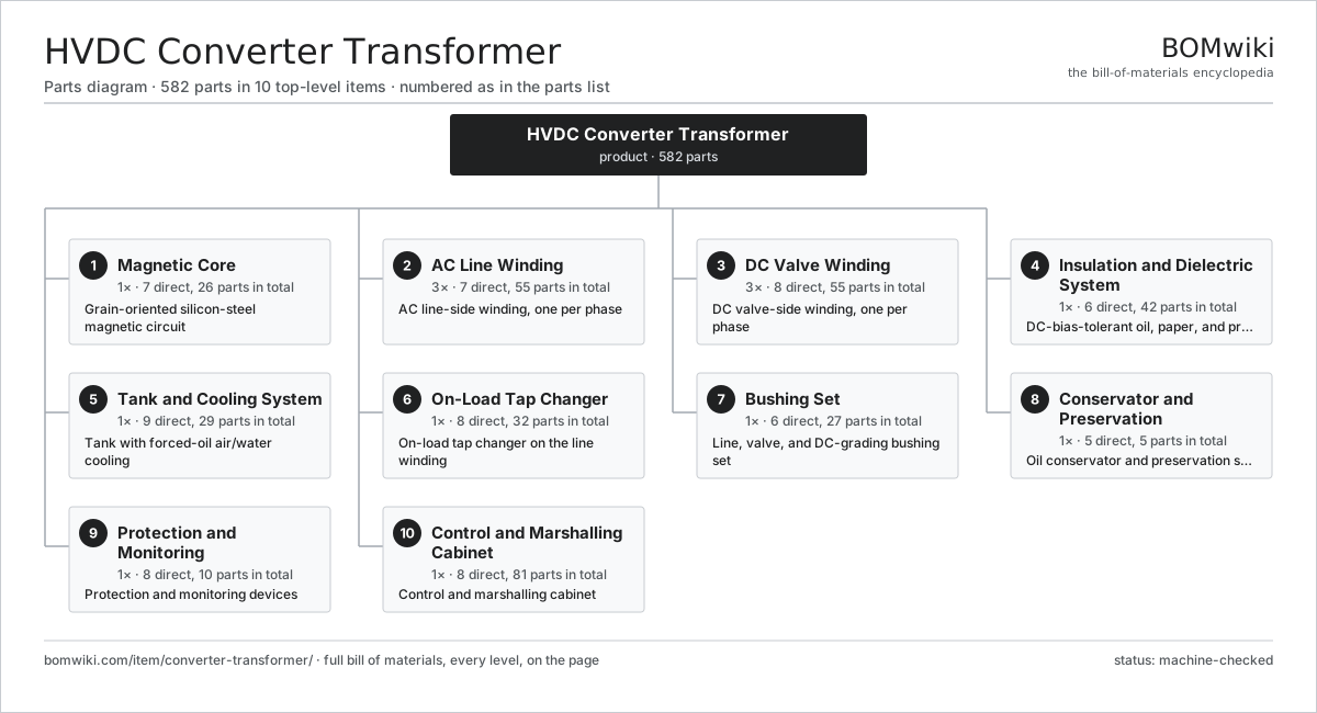
| # | Part | Qty | What it does |
|---|---|---|---|
| 1 | Magnetic Core 7 parts | 1× | Grain-oriented silicon-steel magnetic circuit |
| 2 | AC Line Winding 7 parts | 3× | AC line-side winding, one per phase |
| 3 | DC Valve Winding 8 parts | 3× | DC valve-side winding, one per phase |
| 4 | Insulation and Dielectric System 6 parts | 1× | DC-bias-tolerant oil, paper, and pressboard system |
| 5 | Tank and Cooling System 9 parts | 1× | Tank with forced-oil air/water cooling |
| 6 | On-Load Tap Changer 8 parts | 1× | On-load tap changer on the line winding |
| 7 | Bushing Set 6 parts | 1× | Line, valve, and DC-grading bushing set |
| 8 | Conservator and Preservation 5 parts | 1× | Oil conservator and preservation system |
| 9 | Protection and Monitoring 8 parts | 1× | Protection and monitoring devices |
| 10 | Control and Marshalling Cabinet 8 parts | 1× | Control and marshalling cabinet |
3D model
No 3D model yet. Have a CAD file of this? Add a 3D model. STL renders right on this page; STEP, FreeCAD, and OpenSCAD sources are welcome too (openly licensed, like all 3D models on BOMwiki).
Build & assembly graph
expand / collapse · shared sub-assemblies converge · links to related products · est. labourTap an assembly to expand/collapse · tap a part to open it · use “Open page” for any node · drag to pan, scroll to zoom.
Bill of materials for HVDC Converter Transformer
10 top-level lines · 86 rows shown · 582 parts total · indented to 3 levels| # | Item / sub-assembly | Part no. | Qty/assy | Ext. qty | Parts | Type |
|---|---|---|---|---|---|---|
| 1 | Magnetic Core 7 parts | converter-transformer-core | 1× | 1 | 26 | assembly |
| 1.1 | GO Silicon-Steel Lamination | converter-transformer-core-lamination | 1× | 1 | · | part |
| 1.2 | Core Limb | converter-transformer-core-limb | 2× | 2 | · | part |
| 1.3 | Core Yoke | converter-transformer-core-yoke | 2× | 2 | · | part |
| 1.4 | Core Clamping Frame | converter-transformer-core-clamp | 4× | 4 | · | part |
| 1.5 | Core Tie Rod | converter-transformer-core-tie-rod | 8× | 8 | · | part |
| 1.6 | Core Ground Strap | converter-transformer-core-ground-strap | 1× | 1 | · | part |
| 1.7 | Magnetic Flux Shield | converter-transformer-flux-shield | 8× | 8 | · | part |
| 2 | AC Line Winding 7 parts | converter-transformer-line-winding | 3× | 3 | 55 | assembly |
| 2.1 | Line Copper Conductor | converter-transformer-line-conductor | 1× | 3 | · | part |
| 2.2 | Line Disc Section | converter-transformer-line-disc | 1× | 3 | · | part |
| 2.3 | Regulating Winding | converter-transformer-regulating-winding | 1× | 3 | · | part |
| 2.4 | Winding Support Cylinder | converter-transformer-winding-cylinder | 1× | 3 | · | part |
| 2.5 | Radial Spacer Block | converter-transformer-spacer-block | 48× | 144 | · | part |
| 2.6 | Static Ring | converter-transformer-static-ring | 2× | 6 | · | part |
| 2.7 | Line Lead Exit | converter-transformer-lead-exit | 1× | 3 | · | part |
| 3 | DC Valve Winding 8 parts | converter-transformer-valve-winding | 3× | 3 | 55 | assembly |
| 3.1 | Valve Copper Conductor | converter-transformer-valve-conductor | 1× | 3 | · | part |
| 3.2 | Valve Disc Section | converter-transformer-valve-disc | 1× | 3 | · | part |
| 3.3 | DC Pressboard Barrier | converter-transformer-dc-barrier | 8× | 24 | · | part |
| 3.4 | Winding Support Cylinder | converter-transformer-winding-cylinder | 1× | 3 | · | part |
| 3.5 | Radial Spacer Block | converter-transformer-spacer-block | 40× | 120 | · | part |
| 3.6 | Static Ring | converter-transformer-static-ring | 2× | 6 | · | part |
| 3.7 | Valve-Side Lead | converter-transformer-valve-lead | 1× | 3 | · | part |
| 3.8 | Phase-Shift Connection | converter-transformer-phase-shift-tap | 1× | 3 | · | part |
| 4 | Insulation and Dielectric System 6 parts | converter-transformer-insulation | 1× | 1 | 42 | assembly |
| 4.1 | Mineral Insulating Oil | converter-transformer-mineral-oil | 1× | 1 | · | part |
| 4.2 | Kraft Paper Insulation | converter-transformer-paper-insulation | 1× | 1 | · | part |
| 4.3 | Pressboard Barrier | converter-transformer-pressboard-barrier | 16× | 16 | · | part |
| 4.4 | Pressboard Angle Ring | converter-transformer-angle-ring | 12× | 12 | · | part |
| 4.5 | Lead Support Frame | converter-transformer-lead-support | 8× | 8 | · | part |
| 4.6 | Field-Grading Shielding Electrode | converter-transformer-shielding-electrode | 4× | 4 | · | part |
| 5 | Tank and Cooling System 9 parts | converter-transformer-tank-cooling | 1× | 1 | 29 | assembly |
| 5.1 | Transformer Tank | converter-transformer-tank | 1× | 1 | · | part |
| 5.2 | Tank Cover | converter-transformer-tank-cover | 1× | 1 | · | part |
| 5.3 | Cooling Radiator | converter-transformer-radiator | 8× | 8 | · | part |
| 5.4 | Radiator Fan | converter-transformer-cooling-fan | 12× | 12 | · | part |
| 5.5 | Forced-Oil Pump | converter-transformer-oil-pump | 3× | 3 | · | part |
| 5.6 | Oil-to-Water Cooler | converter-transformer-oil-water-cooler | 1× | 1 | · | part |
| 5.7 | Oil Valve Set | converter-transformer-valve-set | 1× | 1 | · | part |
| 5.8 | Transport Skid | converter-transformer-skid | 1× | 1 | · | part |
| 5.9 | O-Ring Set | oring-set | 1× | 1 | · | part |
| 6 | On-Load Tap Changer 8 parts | converter-transformer-oltc | 1× | 1 | 32 | assembly |
| 6.1 | Diverter Switch | converter-transformer-oltc-diverter | 1× | 1 | · | part |
| 6.2 | Tap Selector | converter-transformer-oltc-selector | 1× | 1 | · | part |
| 6.3 | OLTC Motor Drive Unit | converter-transformer-oltc-drive | 1× | 1 | · | part |
| 6.4 | Transition Resistor | converter-transformer-oltc-transition-resistor | 2× | 2 | · | part |
| 6.5 | Diverter Oil Compartment | converter-transformer-oltc-oil-compartment | 1× | 1 | · | part |
| 6.6 | Helical Gear Pair | gear-pair | 1× | 1 | · | part |
| 6.7 | Servo Motor 4 parts | servo-motor | 1× | 1 | 24 | assembly |
| 6.7.1 | Stator Assembly 3 parts + deeper › | stator-assembly | 1× | 1 | 3 | assembly |
| 6.7.2 | Rotor Assembly 4 parts + deeper › | rotor-assembly | 1× | 1 | 19 | assembly |
| 6.7.3 | Encoder | encoder | 1× | 1 | · | part |
| 6.7.4 | Motor Housing | motor-housing | 1× | 1 | · | part |
| 6.8 | Tap Position Indicator | converter-transformer-oltc-position-indicator | 1× | 1 | · | part |
| 7 | Bushing Set 6 parts | converter-transformer-bushings | 1× | 1 | 27 | assembly |
| 7.1 | AC Line Bushing | converter-transformer-line-bushing | 3× | 3 | · | part |
| 7.2 | Valve-Side Bushing | converter-transformer-valve-bushing | 6× | 6 | · | part |
| 7.3 | Neutral Bushing | converter-transformer-neutral-bushing | 1× | 1 | · | part |
| 7.4 | Bushing Current Transformer | converter-transformer-bushing-ct | 8× | 8 | · | part |
| 7.5 | Bushing Turret | converter-transformer-bushing-turret | 3× | 3 | · | part |
| 7.6 | Valve-Hall Wall Seal | converter-transformer-wall-bushing-seal | 6× | 6 | · | part |
| 8 | Conservator and Preservation 5 parts | converter-transformer-conservator | 1× | 1 | 5 | assembly |
| 8.1 | Conservator Tank | converter-transformer-conservator-tank | 1× | 1 | · | part |
| 8.2 | Conservator Air Cell | converter-transformer-air-cell | 1× | 1 | · | part |
| 8.3 | Silica-Gel Breather | converter-transformer-silica-breather | 1× | 1 | · | part |
| 8.4 | Magnetic Oil-Level Gauge | converter-transformer-oil-level-gauge | 1× | 1 | · | part |
| 8.5 | Conservator Isolating Valve | converter-transformer-conservator-valve | 1× | 1 | · | part |
| 9 | Protection and Monitoring 8 parts | converter-transformer-protection | 1× | 1 | 10 | assembly |
| 9.1 | Buchholz Relay | converter-transformer-buchholz | 1× | 1 | · | part |
| 9.2 | Pressure-Relief Device | converter-transformer-pressure-relief | 1× | 1 | · | part |
| 9.3 | Sudden-Pressure Relay | converter-transformer-sudden-pressure-relay | 1× | 1 | · | part |
| 9.4 | Winding Temperature Indicator | converter-transformer-winding-temp | 2× | 2 | · | part |
| 9.5 | Top-Oil Temperature Indicator | converter-transformer-oil-temp | 1× | 1 | · | part |
| 9.6 | Pressure Sensor | pressure-sensor | 2× | 2 | · | part |
| 9.7 | Online DGA Monitor | converter-transformer-dga-monitor | 1× | 1 | · | part |
| 9.8 | Bushing Condition Monitor | converter-transformer-bushing-monitor | 1× | 1 | · | part |
| 10 | Control and Marshalling Cabinet 8 parts | converter-transformer-marshalling | 1× | 1 | 81 | assembly |
| 10.1 | Marshalling Enclosure | converter-transformer-cabinet-enclosure | 1× | 1 | · | part |
| 10.2 | Cooling-Stage Controller | converter-transformer-cooling-controller | 1× | 1 | · | part |
| 10.3 | Relay | relay | 12× | 12 | · | part |
| 10.4 | Field Terminal Block | converter-transformer-terminal-block | 48× | 48 | · | part |
| 10.5 | Wire Bundle | wire-bundle | 1× | 1 | · | part |
| 10.6 | Connector | connector | 16× | 16 | · | part |
| 10.7 | LCD Panel | lcd-panel | 1× | 1 | · | part |
| 10.8 | Cabinet Space Heater | converter-transformer-space-heater | 1× | 1 | · | part |
Related products
same domain, ranked by shared parts Combined Heat and Power Unit
522 parts · shares 17 with this page
Combined Heat and Power Unit
522 parts · shares 17 with this page
 Electric Arc Furnace Transformer
522 parts · shares 17 with this page
Electric Arc Furnace Transformer
522 parts · shares 17 with this page
 Gas-Insulated Switchgear
281 parts · shares 17 with this page
Gas-Insulated Switchgear
281 parts · shares 17 with this page
 SCR NOx Reduction Unit
569 parts · shares 17 with this page
SCR NOx Reduction Unit
569 parts · shares 17 with this page
 Autotransformer
7,784 parts · shares 16 with this page
Autotransformer
7,784 parts · shares 16 with this page
Sourcing: possible vendors
Browse the supplier directory → Prices, MOQ, and lead times are algorithmic estimates, not quotes, and not claims about these companies. Company mappings are curated by keyword; est. price band $5k–$50M. How estimates work| Vendor | HQ | Specialty | MOQ | Lead time |
|---|---|---|---|---|
| gevernova.com ↗ | Cambridge, US | Power generation | made to order | 20–40 wks |
| siemens-energy.com ↗ | Munich, DE | Power & grid | made to order | 20–40 wks |
| hitachienergy.com ↗ | Zurich, CH | Grid & transformers | made to order | 20–40 wks |
|
🇨🇭ABB
abb.com ↗
|
Zurich, CH | Electrification & automation | made to order | 20–40 wks |
| se.com ↗ | Rueil-Malmaison, FR | Electrical & automation | made to order | 20–40 wks |
990-word article