Biogas Generator (CHP)
ProductOverview
A biogas generator turns the methane from a digester, landfill or wastewater plant into both electricity and useful heat. Rather than flaring the gas, it burns it in a reciprocating engine driving an alternator, and then captures the heat the engine would otherwise waste, from its cooling jacket and its hot exhaust, into a hot-water loop. Running both products together is what makes the set efficient: a third of the fuel's energy becomes electricity, and most of the rest is recovered as heat, so very little is thrown away.
How it works
Cleaned fuel feeds the Gas Engine, a spark-ignition unit whose pistons drive a crankshaft in a cast block. Biogas is not pipeline gas, it is wet, low in energy and laced with corrosive hydrogen sulphide, so it first passes through the Gas Treatment Skid skid, where a filter strips the sulphide and a blower lifts the gas to engine pressure. Inside the engine, the Fuel-Gas Train meters the gas and blends it with air in a venturi mixer, the Turbocharger boosts the charge, and the Ignition System fires a spark plug in each cylinder.
The crankshaft turns the Synchronous Alternator, a brushless synchronous machine whose voltage regulator holds a steady output as the load swings. That power cannot simply be dumped onto the grid: the Control & Synchronising Panel governs engine speed, watches the grid voltage and phase, and only closes its synchronising breaker once the alternator is matched, all while its protection relays stand ready to trip on a fault.
Heat is the second product. The Cooling & Heat Recovery carries coolant through the engine and through recovery exchangers that pull heat from the jacket water and the exhaust into a building or process loop, with a radiator to shed whatever heat the site cannot use. The whole gen-set sits inside an Acoustic Enclosure that silences it and keeps the weather out.
Biogas Generator (CHP) parts and their functions
6 top-level parts · 338 parts in total · full bill of materials below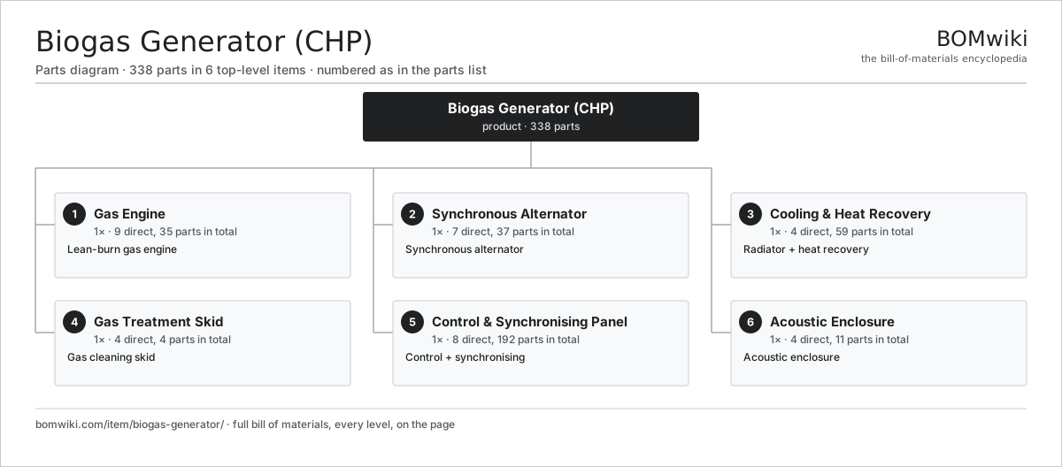
| # | Part | Qty | What it does |
|---|---|---|---|
| 1 | Gas Engine 9 parts | 1× | Lean-burn gas engine |
| 2 | Synchronous Alternator 7 parts | 1× | Synchronous alternator |
| 3 | Cooling & Heat Recovery 4 parts | 1× | Radiator + heat recovery |
| 4 | Gas Treatment Skid 4 parts | 1× | Gas cleaning skid |
| 5 | Control & Synchronising Panel 8 parts | 1× | Control + synchronising |
| 6 | Acoustic Enclosure 4 parts | 1× | Acoustic enclosure |
3D model
No 3D model yet. Have a CAD file of this? Add a 3D model. STL renders right on this page; STEP, FreeCAD, and OpenSCAD sources are welcome too (openly licensed, like all 3D models on BOMwiki).
Build & assembly graph
expand / collapse · shared sub-assemblies converge · links to related products · est. labourTap an assembly to expand/collapse · tap a part to open it · use “Open page” for any node · drag to pan, scroll to zoom.
Bill of materials for Biogas Generator (CHP)
6 top-level lines · 62 rows shown · 338 parts total · indented to 3 levels| # | Item / sub-assembly | Part no. | Qty/assy | Ext. qty | Parts | Type |
|---|---|---|---|---|---|---|
| 1 | Gas Engine 9 parts | biogas-engine | 1× | 1 | 35 | assembly |
| 1.1 | Engine Block | biogas-engine-block | 1× | 1 | · | part |
| 1.2 | Piston | biogas-piston | 6× | 6 | · | part |
| 1.3 | Crankshaft | biogas-crankshaft | 1× | 1 | · | part |
| 1.4 | Cylinder Head | biogas-cylinder-head | 1× | 1 | · | part |
| 1.5 | Ignition System 4 parts | biogas-ignition-system | 1× | 1 | 14 | assembly |
| 1.5.1 | Spark Plug | spark-plug | 6× | 6 | · | part |
| 1.5.2 | Ignition Coil | biogas-ignition-coil | 6× | 6 | · | part |
| 1.5.3 | Bare PCB | pcb-bare | 1× | 1 | · | part |
| 1.5.4 | Microcontroller | mcu | 1× | 1 | · | part |
| 1.6 | Fuel-Gas Train 4 parts | biogas-gas-train | 1× | 1 | 5 | assembly |
| 1.6.1 | Gas Regulator | biogas-gas-regulator | 1× | 1 | · | part |
| 1.6.2 | Air/Gas Mixer | biogas-gas-mixer | 1× | 1 | · | part |
| 1.6.3 | Relay | relay | 2× | 2 | · | part |
| 1.6.4 | Flame Arrestor | biogas-flame-arrestor | 1× | 1 | · | part |
| 1.7 | Turbocharger | biogas-turbocharger | 1× | 1 | · | part |
| 1.8 | Ball Bearing | ball-bearing | 4× | 4 | · | part |
| 1.9 | Oil Seal | oil-seal | 2× | 2 | · | part |
| 2 | Synchronous Alternator 7 parts | biogas-alternator | 1× | 1 | 37 | assembly |
| 2.1 | Stator Assembly 3 parts | stator-assembly | 1× | 1 | 3 | assembly |
| 2.1.1 | Stator Core (laminations) | stator-core | 1× | 1 | · | part |
| 2.1.2 | Copper Winding | copper-winding | 1× | 1 | · | part |
| 2.1.3 | Slot Insulation | stator-insulation | 1× | 1 | · | part |
| 2.2 | Rotor Assembly 4 parts | rotor-assembly | 1× | 1 | 19 | assembly |
| 2.2.1 | Rotor Shaft | rotor-shaft | 1× | 1 | · | part |
| 2.2.2 | Rotor Core | rotor-core | 1× | 1 | · | part |
| 2.2.3 | Neodymium Magnet | neodymium-magnet | 16× | 16 | · | part |
| 2.2.4 | Ball Bearing | ball-bearing | 1× | 1 | · | part |
| 2.3 | Copper Winding | copper-winding | 3× | 3 | · | part |
| 2.4 | Neodymium Magnet | neodymium-magnet | 8× | 8 | · | part |
| 2.5 | Motor Housing | motor-housing | 1× | 1 | · | part |
| 2.6 | Ball Bearing | ball-bearing | 2× | 2 | · | part |
| 2.7 | Automatic Voltage Regulator | biogas-avr | 1× | 1 | · | part |
| 3 | Cooling & Heat Recovery 4 parts | biogas-cooling-system | 1× | 1 | 59 | assembly |
| 3.1 | Radiator | biogas-radiator | 1× | 1 | · | part |
| 3.2 | Heat-Recovery Exchanger | biogas-heat-exchanger | 2× | 2 | · | part |
| 3.3 | Coolant Pump 5 parts | biogas-coolant-pump | 2× | 2 | 25 | assembly |
| 3.3.1 | Stator Assembly 3 parts + deeper › | stator-assembly | 1× | 2 | 3 | assembly |
| 3.3.2 | Rotor Assembly 4 parts + deeper › | rotor-assembly | 1× | 2 | 19 | assembly |
| 3.3.3 | Copper Winding | copper-winding | 1× | 2 | · | part |
| 3.3.4 | Pump Impeller | biogas-pump-impeller | 1× | 2 | · | part |
| 3.3.5 | Oil Seal | oil-seal | 1× | 2 | · | part |
| 3.4 | Coolant Hose | biogas-coolant-hose | 6× | 6 | · | part |
| 4 | Gas Treatment Skid 4 parts | biogas-gas-treatment | 1× | 1 | 4 | assembly |
| 4.1 | Gas Filter | biogas-gas-filter | 1× | 1 | · | part |
| 4.2 | Blower Motor | blower-motor | 1× | 1 | · | part |
| 4.3 | Condensate Trap | biogas-condensate-trap | 1× | 1 | · | part |
| 4.4 | Pressure Sensor | pressure-sensor | 1× | 1 | · | part |
| 5 | Control & Synchronising Panel 8 parts | biogas-control-panel | 1× | 1 | 192 | assembly |
| 5.1 | Compute SoC Module | soc-module | 1× | 1 | · | part |
| 5.2 | Microcontroller | mcu | 1× | 1 | · | part |
| 5.3 | Bare PCB | pcb-bare | 1× | 1 | · | part |
| 5.4 | LCD Panel | lcd-panel | 1× | 1 | · | part |
| 5.5 | Touch Digitizer | touch-digitizer | 1× | 1 | · | part |
| 5.6 | Relay | relay | 6× | 6 | · | part |
| 5.7 | Synchronising Breaker | biogas-sync-breaker | 1× | 1 | · | part |
| 5.8 | SMD Passive (R/C/L) | smd-passives | 180× | 180 | · | part |
| 6 | Acoustic Enclosure 4 parts | biogas-enclosure | 1× | 1 | 11 | assembly |
| 6.1 | Sheet Metal Panel | sheet-panel | 8× | 8 | · | part |
| 6.2 | Acoustic Liner | biogas-acoustic-liner | 1× | 1 | · | part |
| 6.3 | Exhaust Silencer | biogas-exhaust-silencer | 1× | 1 | · | part |
| 6.4 | Fastener Set | fastener-set | 1× | 1 | · | part |
Something wrong in this list? Report a problem with this BOM.
Related products
same domain, ranked by shared parts Geothermal Heat Pump
214 parts · shares 15 with this page
 Flywheel Energy Storage
285 parts · shares 14 with this page
Fire-Tube Boiler
74 parts · shares 13 with this page
Automatic Transfer Switch
212 parts · shares 12 with this page
Gas Turbine
2,089 parts · shares 11 with this page
 Automatic Voltage Regulator
83 parts · shares 13 with this page
Sourcing: possible vendors
Browse the supplier directory → Prices, MOQ, and lead times are algorithmic estimates, not quotes, and not claims about these companies. Company mappings are curated by keyword; est. price band $5k–$50M. How estimates work| Vendor | HQ | Specialty | MOQ | Lead time |
|---|---|---|---|---|
| gevernova.com ↗ | Cambridge, US | Power generation | made to order | 20–40 wks |
| siemens-energy.com ↗ | Munich, DE | Power & grid | made to order | 20–40 wks |
| hitachienergy.com ↗ | Zurich, CH | Grid & transformers | made to order | 20–40 wks |
|
🇨🇭ABB
abb.com ↗
|
Zurich, CH | Electrification & automation | made to order | 20–40 wks |
| se.com ↗ | Rueil-Malmaison, FR | Electrical & automation | made to order | 20–40 wks |
321-word article