Dry-Type Transformer
ProductOverview
A Dry-Type Transformer performs the same voltage transformation as an oil-filled unit but uses solid epoxy resin and air instead of insulating oil. That single change makes it suited to indoor and fire-sensitive sites: hospitals, high-rise buildings, ships, data centres, tunnels and chemical plants, where an oil fire or a spill would be unacceptable. The cast-resin version, the most common type for medium-voltage distribution, encases each high-voltage coil in a void-free epoxy body that is self-extinguishing and does not leak.
Ratings typically run from a few hundred kVA up to about 25 MVA at distribution voltages of 6.6, 11, 22 or 33 kV. Because there is no oil, there is no conservator, no Buchholz relay and no oil sampling regime, which simplifies installation and maintenance. The trade-offs are a higher cost per kVA, a lower overload capacity and audible-noise characteristics that need attention in occupied spaces.
Magnetic core
The Magnetic Core is built from grain-oriented silicon-steel laminations in the same way as an oil transformer, with limbs and yokes forming the magnetic loop. Step-lap joints are used to reduce the localised flux crowding that causes hum, since these units often sit close to people. Clamping frames and tie rods hold the stack, and anti-vibration pads under the core feet stop magnetostrictive hum reaching the base frame and the building structure. The core is earthed once through the earthing strap.
Cast-resin windings
The winding assembly is what defines a cast-resin unit. The high-voltage coil is layer-wound from enamelled conductor with inter-layer film, reinforced with glass-fibre mesh, and then cast in epoxy resin under vacuum. The vacuum step is essential: it pulls air out of the casting so no voids remain, because a void would ionise under voltage and start partial discharge that erodes the insulation. An embedded field-grading shield smooths the electric field at the coil ends to keep partial discharge below the IEC limit, usually under 10 pC.
The low-voltage coil is wound from conductor foil rather than wire. A full-width foil makes every turn carry the same current along its whole height, which gives even heating and strong resistance to the axial forces of a short circuit. The foil layers are insulated by film and impregnated with resin. Glass-fibre spacer bars set the cooling air gap between the LV and HV coils.
Resin and dielectric system
The resin system replaces oil as the bulk dielectric. The epoxy resin is mixed with a hardener and heavily loaded with silica filler so the cured body conducts heat away from the conductors and expands at nearly the same rate as the copper or aluminium inside it. Matching the thermal expansion matters because the coil is cycled through wide temperature swings in service, and a mismatch would crack the casting. Coils are formed in machined moulds and cured at temperature to develop full cross-linking and Class F or Class H thermal rating.
Enclosure and cooling
With no oil to carry heat to external radiators, a dry-type transformer is cooled directly by air over the coil surfaces. The enclosure and cooling system uses vertical air ducts through and around the coils so convection draws cool air up past the windings. In its natural-air (AN) mode the unit relies on convection alone. Adding forced-air fans gives the AF rating, raising continuous capacity by 25 to 40 percent for peak periods. The sheet-steel enclosure carries ventilation louvres and guard mesh to give an ingress-protection rating from IP21 up to IP54 while still admitting airflow.
Tap setting, terminations and protection
Ratio is set by an off-circuit tap arrangement: bolted tap links on a tap busbar are moved when the transformer is de-energised. The terminations bring the HV connection in through stand-off insulators and take the LV current out on busbars, with a removable neutral link for earthing.
Protection is thermal rather than gas-based. PT100 sensors cast into the LV coils feed a temperature controller that stages the fans, raises an alarm and trips the unit if a coil exceeds its class limit, with a backup cutoff behind it. The controller and fan contactors sit in the control cabinet.
Standards and application
Cast-resin transformers are built and tested to IEC 60076-11 and IEEE C57.12.01, which set the partial-discharge, climatic (C), environmental (E) and fire-behaviour (F) classes. The top fire class, F1, requires the unit to be self-extinguishing and to emit limited smoke, which is the property that lets a dry-type unit sit directly inside an occupied building where an oil-filled transformer would need a separate fire-rated vault.
Dry-Type Transformer parts and their functions
9 top-level parts · 2,807 parts in total · full bill of materials below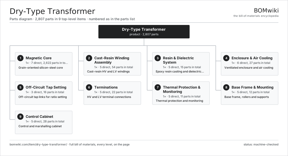
| # | Part | Qty | What it does |
|---|---|---|---|
| 1 | Magnetic Core 7 parts | 1× | Grain-oriented silicon-steel core |
| 2 | Cast-Resin Winding Assembly 5 parts | 1× | Cast-resin HV and LV windings |
| 3 | Resin & Dielectric System 5 parts | 1× | Epoxy resin casting and dielectric system |
| 4 | Enclosure & Air Cooling 6 parts | 1× | Ventilated enclosure and air cooling |
| 5 | Off-Circuit Tap Setting 3 parts | 1× | Off-circuit tap links for ratio setting |
| 6 | Terminations 5 parts | 1× | HV and LV terminal connections |
| 7 | Thermal Protection & Monitoring 5 parts | 1× | Thermal protection and monitoring |
| 8 | Base Frame & Mounting 5 parts | 1× | Base frame, rollers and supports |
| 9 | Control Cabinet 5 parts | 1× | Control and marshalling cabinet |
3D model
No 3D model yet. Have a CAD file of this? Add a 3D model. STL renders right on this page; STEP, FreeCAD, and OpenSCAD sources are welcome too (openly licensed, like all 3D models on BOMwiki).
Build & assembly graph
expand / collapse · shared sub-assemblies converge · links to related products · est. labourTap an assembly to expand/collapse · tap a part to open it · use “Open page” for any node · drag to pan, scroll to zoom.
Bill of materials for Dry-Type Transformer
9 top-level lines · 62 rows shown · 2,807 parts total · indented to 3 levels| # | Item / sub-assembly | Part no. | Qty/assy | Ext. qty | Parts | Type |
|---|---|---|---|---|---|---|
| 1 | Magnetic Core 7 parts | dry-type-transformer-core | 1× | 1 | 2,622 | assembly |
| 1.1 | GO Silicon-Steel Lamination | dry-type-transformer-core-lamination | 2600× | 2,600 | · | part |
| 1.2 | Core Limb | dry-type-transformer-core-limb | 3× | 3 | · | part |
| 1.3 | Core Yoke | dry-type-transformer-core-yoke | 2× | 2 | · | part |
| 1.4 | Core Clamping Frame | dry-type-transformer-clamping-frame | 2× | 2 | · | part |
| 1.5 | Core Tie Rod | dry-type-transformer-core-tie-rod | 6× | 6 | · | part |
| 1.6 | Core Earthing Strap | dry-type-transformer-core-ground-strap | 1× | 1 | · | part |
| 1.7 | Anti-Vibration Pad | dry-type-transformer-isolation-pad | 8× | 8 | · | part |
| 2 | Cast-Resin Winding Assembly 5 parts | dry-type-transformer-windings | 1× | 1 | 54 | assembly |
| 2.1 | HV Cast-Resin Coil 4 parts | dry-type-transformer-hv-coil | 3× | 3 | 4 | assembly |
| 2.1.1 | HV Coil Conductor | dry-type-transformer-hv-conductor | 1× | 3 | · | part |
| 2.1.2 | Inter-Layer Insulation | dry-type-transformer-layer-insulation | 1× | 3 | · | part |
| 2.1.3 | Glass-Fibre Reinforcement Mesh | dry-type-transformer-glass-mesh | 1× | 3 | · | part |
| 2.1.4 | Epoxy Casting Resin | dry-type-transformer-epoxy-resin | 1× | 3 | · | part |
| 2.2 | LV Foil Coil 3 parts | dry-type-transformer-lv-coil | 3× | 3 | 3 | assembly |
| 2.2.1 | LV Conductor Foil | dry-type-transformer-lv-foil | 1× | 3 | · | part |
| 2.2.2 | Foil Inter-Layer Film | dry-type-transformer-interlayer-film | 1× | 3 | · | part |
| 2.2.3 | Epoxy Casting Resin | dry-type-transformer-epoxy-resin | 1× | 3 | · | part |
| 2.3 | Off-Circuit Tap Link | dry-type-transformer-tap-link | 3× | 3 | · | part |
| 2.4 | Coil Support Block | dry-type-transformer-coil-support | 6× | 6 | · | part |
| 2.5 | Glass-Fibre Spacer Bar | dry-type-transformer-spacer-bar | 24× | 24 | · | part |
| 3 | Resin & Dielectric System 5 parts | dry-type-transformer-resin-system | 1× | 1 | 15 | assembly |
| 3.1 | Epoxy Casting Resin | dry-type-transformer-epoxy-resin | 1× | 1 | · | part |
| 3.2 | Epoxy Hardener | dry-type-transformer-hardener | 1× | 1 | · | part |
| 3.3 | Silica Filler | dry-type-transformer-filler | 1× | 1 | · | part |
| 3.4 | Coil Casting Mould | dry-type-transformer-mould | 6× | 6 | · | part |
| 3.5 | PD Field-Grading Shield | dry-type-transformer-partial-discharge-shield | 6× | 6 | · | part |
| 4 | Enclosure & Air Cooling 6 parts | dry-type-transformer-enclosure-cooling | 1× | 1 | 27 | assembly |
| 4.1 | Sheet Metal Panel | sheet-panel | 8× | 8 | · | part |
| 4.2 | Ventilation Louvre | dry-type-transformer-louvre | 4× | 4 | · | part |
| 4.3 | Enclosure Cooling Fan | dry-type-transformer-cooling-fan | 6× | 6 | · | part |
| 4.4 | Coil Air Duct | dry-type-transformer-air-duct | 6× | 6 | · | part |
| 4.5 | IP Guard Mesh | dry-type-transformer-mesh-guard | 2× | 2 | · | part |
| 4.6 | Fastener Set | fastener-set | 1× | 1 | · | part |
| 5 | Off-Circuit Tap Setting 3 parts | dry-type-transformer-detc | 1× | 1 | 16 | assembly |
| 5.1 | Tap Busbar | dry-type-transformer-tap-busbar | 3× | 3 | · | part |
| 5.2 | Tap Selection Bolt | dry-type-transformer-tap-bolt | 12× | 12 | · | part |
| 5.3 | Tap Marking Plate | dry-type-transformer-tap-label | 1× | 1 | · | part |
| 6 | Terminations 5 parts | dry-type-transformer-terminations | 1× | 1 | 22 | assembly |
| 6.1 | HV Terminal | dry-type-transformer-hv-terminal | 3× | 3 | · | part |
| 6.2 | LV Busbar | dry-type-transformer-lv-busbar | 4× | 4 | · | part |
| 6.3 | Stand-Off Insulator | dry-type-transformer-standoff-insulator | 6× | 6 | · | part |
| 6.4 | Cable Lug | cable-lug | 8× | 8 | · | part |
| 6.5 | Neutral Earthing Link | dry-type-transformer-neutral-link | 1× | 1 | · | part |
| 7 | Thermal Protection & Monitoring 5 parts | dry-type-transformer-protection | 1× | 1 | 11 | assembly |
| 7.1 | PT100 Coil Sensor | dry-type-transformer-pt100-sensor | 4× | 4 | · | part |
| 7.2 | Temperature Controller | dry-type-transformer-temp-controller | 1× | 1 | · | part |
| 7.3 | LCD Panel | lcd-panel | 1× | 1 | · | part |
| 7.4 | Relay | relay | 4× | 4 | · | part |
| 7.5 | Backup Thermal Cutoff | dry-type-transformer-overtemp-fuse | 1× | 1 | · | part |
| 8 | Base Frame & Mounting 5 parts | dry-type-transformer-mounting | 1× | 1 | 12 | assembly |
| 8.1 | Base Frame | dry-type-transformer-base-frame | 1× | 1 | · | part |
| 8.2 | Transport Roller | dry-type-transformer-roller | 4× | 4 | · | part |
| 8.3 | Lifting Lug | dry-type-transformer-lifting-lug | 4× | 4 | · | part |
| 8.4 | Earthing Terminal | dry-type-transformer-earth-terminal | 2× | 2 | · | part |
| 8.5 | Fastener Set | fastener-set | 1× | 1 | · | part |
| 9 | Control Cabinet 5 parts | dry-type-transformer-control-cabinet | 1× | 1 | 28 | assembly |
| 9.1 | Sheet Metal Panel | sheet-panel | 4× | 4 | · | part |
| 9.2 | Fan Contactor | dry-type-transformer-fan-contactor | 2× | 2 | · | part |
| 9.3 | Terminal Block | dry-type-transformer-terminal-block | 20× | 20 | · | part |
| 9.4 | Wire Bundle | wire-bundle | 1× | 1 | · | part |
| 9.5 | Cabinet Anti-Condensation Heater | dry-type-transformer-cabinet-heater | 1× | 1 | · | part |
Related products
same domain, ranked by shared parts Automatic Voltage Regulator
83 parts · shares 3 with this page
Bottom Ash Handling System
1,782 parts · shares 3 with this page
Automatic Voltage Regulator
83 parts · shares 3 with this page
Bottom Ash Handling System
1,782 parts · shares 3 with this page
 Combined Heat and Power Unit
522 parts · shares 3 with this page
Containerized Diesel Genset
655 parts · shares 3 with this page
Combined Heat and Power Unit
522 parts · shares 3 with this page
Containerized Diesel Genset
655 parts · shares 3 with this page
Sourcing: possible vendors
Browse the supplier directory → Prices, MOQ, and lead times are algorithmic estimates, not quotes, and not claims about these companies. Company mappings are curated by keyword; est. price band $5k–$50M. How estimates work| Vendor | HQ | Specialty | MOQ | Lead time |
|---|---|---|---|---|
| gevernova.com ↗ | Cambridge, US | Power generation | made to order | 20–40 wks |
| siemens-energy.com ↗ | Munich, DE | Power & grid | made to order | 20–40 wks |
| hitachienergy.com ↗ | Zurich, CH | Grid & transformers | made to order | 20–40 wks |
|
🇨🇭ABB
abb.com ↗
|
Zurich, CH | Electrification & automation | made to order | 20–40 wks |
| se.com ↗ | Rueil-Malmaison, FR | Electrical & automation | made to order | 20–40 wks |
1,005-word article