Steam Surface Condenser
ProductOverview
A steam surface condenser is the cold end of the Rankine cycle in a steam power plant. It receives exhaust steam leaving the low-pressure turbine and condenses it back to water by transferring the latent heat of the steam to cooling water flowing through thousands of tubes. The condensed water, called condensate, drains into a Hotwell at the base of the shell and returns to the boiler feed system. The condenser does two jobs at once. It closes the water loop so the working fluid is recovered and reused, and it holds the turbine exhaust at a deep vacuum so the turbine can extract the maximum possible work from each kilogram of steam.
The vacuum is the reason a condenser matters to plant efficiency. Steam at 50 mbar absolute condenses at about 33 °C, far below atmospheric boiling. Each millibar of back pressure the condenser fails to hold costs measurable turbine output, because the turbine sees a smaller pressure ratio across its last stages. A condenser that runs 10 mbar higher than design raises unit heat rate, which over a year of base-load running is a large fuel cost. Keeping the back pressure low depends on clean tubes, cold cooling water, and effective removal of air.
Shell-and-tube heat transfer
The condenser is a large shell-and-tube exchanger built for vacuum service rather than pressure. Exhaust steam enters the top through the Exhaust Steam Neck and flows down across the outside of the tubes in the Tube Bundle. Cooling water flows inside the tubes, entering through the Inlet Water Box and leaving through the Outlet Water Box. The tubes are rolled into a Tube Sheet at each end, which separates the cooling water from the steam space.
Heat transfer is dominated by the condensing film on the steam side. A thin film of condensate forms on each tube and drains downward by gravity, dripping from tube to tube through the bundle. The bundle is laid out so the steam can penetrate to the inner rows without flooding them with condensate from the rows above. An Impingement Baffle protects the top rows from the high velocity of the incoming steam, which would otherwise erode the thin tube walls. Tube Support Plate sets the unsupported tube span so that flow-induced vibration stays below the tube natural frequency, and where the spans are long, an Anti-Vibration Stake damps the rows further.
Air removal and air binding
Even a tight condenser leaks. Air enters through flange gaskets, valve packings, and any joint below atmospheric pressure, and dissolved gases come out of the steam itself. Non-condensable gas is the enemy of a condenser because it does not condense and it blankets the tube surface, raising the local resistance to heat transfer and depressing the vacuum. This effect is called air binding. To fight it, the bundle includes an Air Cooling Section, a shrouded region where the air-vapor mixture is sub-cooled so the steam fraction condenses out and the remaining gas becomes concentrated. The concentrated mixture is drawn off through the Air Offtake Connection.
The Air Removal System system pulls this mixture out continuously. The Liquid Ring Vacuum Pump is a liquid ring machine that compresses the gas from condenser pressure up to atmosphere and discharges it through a Air Separator Tank. One pump runs while a second stands by. During startup a hogging mode pulls the shell down from atmosphere to operating vacuum before steam is admitted. The Pressure Sensor readings on the shell tell the operator whether the air removal is keeping pace with in-leakage.
Tube materials and corrosion
Tube life sets the maintenance interval for the whole machine, so material selection is driven by the cooling water. Fresh water with good chemistry can use stainless steel or 90/10 copper-nickel. Brackish or seawater cooling pushes the choice toward titanium, which is effectively immune to the chloride pitting and erosion that destroy copper alloys. The Condenser Tube here is titanium for that reason. The Tube Sheet is Muntz metal or naval brass, and because joining titanium tubes to a brass tube sheet creates a galvanic couple, the water box carries a Sacrificial Anode and the tube sheet face takes a Tube Sheet Coating to steer corrosion away from the joint. The carbon steel water boxes are rubber lined for the same protection.
Hotwell, condensate, and deaeration
Condensate collects in the Hotwell, which provides suction head for the condensate extraction pump and a small buffer volume against load swings. A Hotwell Level Transmitter controls level by admitting demineralized water through the Makeup Water Valve when the cycle loses inventory. The makeup enters through a Makeup Spray Header so it is exposed to the steam space and deaerated rather than dumped in cold.
Dissolved oxygen control happens in the condenser itself. As condensate falls through the steam space it is reheated to saturation, which drives oxygen out of solution where the air removal system can carry it away. A well-designed condenser delivers condensate below 10 ppb dissolved oxygen, which protects the feedwater train and boiler from oxygen pitting. A Vortex Breaker over the outlet keeps the extraction pump from drawing air down a vortex.
Fouling, cleaning, and failures
Cooling water deposits scale, silt, and biofilm on the tube bores, and each layer adds thermal resistance that raises the back pressure. The cleanliness factor tracks how far the real heat transfer has fallen below the clean-tube value. The On-Load Tube Cleaning System system fights fouling on load by circulating a Sponge Cleaning Ball charge through the tubes; the slightly oversized sponge balls wipe each bore and are recovered at the Ball Collector Strainer for reuse.
The failure that matters most is a tube leak. Because the cooling water is at higher pressure than the vacuum steam space, a cracked or eroded tube lets raw cooling water into the condensate. That contamination shows up first as a rise in condensate conductivity at the Conductivity Cell, well before it would damage the boiler. Operators trend conductivity to find a leak early, then isolate the affected water box, locate the tube by helium or foam testing, and plug it. Other recurring problems are air in-leakage that the Liquid Ring Vacuum Pump cannot overcome, tube vibration where supports have corroded, and loss of vacuum from a fouled air cooling section.
Steam Surface Condenser parts and their functions
8 top-level parts · 270 parts in total · full bill of materials below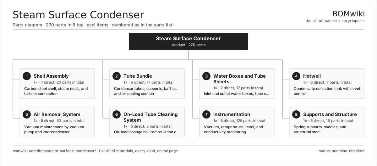
| # | Part | Qty | What it does |
|---|---|---|---|
| 1 | Shell Assembly 7 parts | 1× | Carbon steel shell, steam neck, and turbine connection |
| 2 | Tube Bundle 6 parts | 1× | Condenser tubes, supports, baffles, and air cooling section |
| 3 | Water Boxes and Tube Sheets 7 parts | 1× | Inlet and outlet water boxes, tube sheets, divider plates |
| 4 | Hotwell 6 parts | 1× | Condensate collection tank with level control |
| 5 | Air Removal System 5 parts | 1× | Vacuum maintenance by vacuum pump and intercondenser |
| 6 | On-Load Tube Cleaning System 5 parts | 1× | On-load sponge ball recirculation cleaning system |
| 7 | Instrumentation 5 parts | 1× | Vacuum, temperature, level, and conductivity monitoring |
| 8 | Supports and Structure 5 parts | 1× | Spring supports, saddles, and structural steel |
3D model
No 3D model yet. Have a CAD file of this? Add a 3D model. STL renders right on this page; STEP, FreeCAD, and OpenSCAD sources are welcome too (openly licensed, like all 3D models on BOMwiki).
Build & assembly graph
expand / collapse · shared sub-assemblies converge · links to related products · est. labourTap an assembly to expand/collapse · tap a part to open it · use “Open page” for any node · drag to pan, scroll to zoom.
Bill of materials for Steam Surface Condenser
8 top-level lines · 71 rows shown · 270 parts total · indented to 3 levels| # | Item / sub-assembly | Part no. | Qty/assy | Ext. qty | Parts | Type |
|---|---|---|---|---|---|---|
| 1 | Shell Assembly 7 parts | steam-surface-condenser-shell | 1× | 1 | 20 | assembly |
| 1.1 | Shell Plate | steam-surface-condenser-shell-plate | 6× | 6 | · | part |
| 1.2 | Exhaust Steam Neck | steam-surface-condenser-steam-neck | 1× | 1 | · | part |
| 1.3 | Turbine Expansion Joint | steam-surface-condenser-expansion-joint | 1× | 1 | · | part |
| 1.4 | Shell Stiffener Ring | steam-surface-condenser-shell-stiffener | 8× | 8 | · | part |
| 1.5 | Shell Manhole | steam-surface-condenser-shell-manhole | 2× | 2 | · | part |
| 1.6 | Atmospheric Relief Disc | steam-surface-condenser-rupture-disc | 1× | 1 | · | part |
| 1.7 | Steam Dump Diffuser | steam-surface-condenser-dump-connection | 1× | 1 | · | part |
| 2 | Tube Bundle 6 parts | steam-surface-condenser-tube-bundle | 1× | 1 | 17 | assembly |
| 2.1 | Condenser Tube | steam-surface-condenser-tube | 1× | 1 | · | part |
| 2.2 | Tube Support Plate | steam-surface-condenser-tube-support-plate | 9× | 9 | · | part |
| 2.3 | Impingement Baffle | steam-surface-condenser-impingement-baffle | 1× | 1 | · | part |
| 2.4 | Steam Dome Baffle | steam-surface-condenser-steam-dome-baffle | 2× | 2 | · | part |
| 2.5 | Air Cooling Section 3 parts | steam-surface-condenser-air-cooling-section | 1× | 1 | 3 | assembly |
| 2.5.1 | Air Section Tube | steam-surface-condenser-air-section-tube | 1× | 1 | · | part |
| 2.5.2 | Air Section Shroud | steam-surface-condenser-air-section-shroud | 1× | 1 | · | part |
| 2.5.3 | Air Offtake Connection | steam-surface-condenser-air-offtake | 1× | 1 | · | part |
| 2.6 | Anti-Vibration Stake | steam-surface-condenser-tube-stake | 1× | 1 | · | part |
| 3 | Water Boxes and Tube Sheets 7 parts | steam-surface-condenser-waterbox | 1× | 1 | 17 | assembly |
| 3.1 | Inlet Water Box | steam-surface-condenser-inlet-waterbox | 1× | 1 | · | part |
| 3.2 | Outlet Water Box | steam-surface-condenser-outlet-waterbox | 1× | 1 | · | part |
| 3.3 | Tube Sheet | steam-surface-condenser-tube-sheet | 2× | 2 | · | part |
| 3.4 | Pass Divider Plate | steam-surface-condenser-divider-plate | 2× | 2 | · | part |
| 3.5 | Water Box Manhole | steam-surface-condenser-waterbox-manhole | 2× | 2 | · | part |
| 3.6 | Sacrificial Anode | steam-surface-condenser-sacrificial-anode | 8× | 8 | · | part |
| 3.7 | Tube Sheet Coating | steam-surface-condenser-tube-sheet-coating | 1× | 1 | · | part |
| 4 | Hotwell 6 parts | steam-surface-condenser-hotwell | 1× | 1 | 7 | assembly |
| 4.1 | Hotwell Tank | steam-surface-condenser-hotwell-tank | 1× | 1 | · | part |
| 4.2 | Condensate Outlet Strainer | steam-surface-condenser-condensate-outlet | 1× | 1 | · | part |
| 4.3 | Hotwell Level Transmitter | steam-surface-condenser-hotwell-level-transmitter | 2× | 2 | · | part |
| 4.4 | Makeup Water Valve | steam-surface-condenser-makeup-valve | 1× | 1 | · | part |
| 4.5 | Makeup Spray Header | steam-surface-condenser-makeup-spray | 1× | 1 | · | part |
| 4.6 | Vortex Breaker | steam-surface-condenser-hotwell-vortex-breaker | 1× | 1 | · | part |
| 5 | Air Removal System 5 parts | steam-surface-condenser-air-removal | 1× | 1 | 63 | assembly |
| 5.1 | Liquid Ring Vacuum Pump 7 parts | steam-surface-condenser-vacuum-pump | 2× | 2 | 29 | assembly |
| 5.1.1 | Rotor Assembly 4 parts + deeper › | rotor-assembly | 1× | 2 | 19 | assembly |
| 5.1.2 | Stator Assembly 3 parts + deeper › | stator-assembly | 1× | 2 | 3 | assembly |
| 5.1.3 | Vacuum Pump Shaft | steam-surface-condenser-pump-shaft | 1× | 2 | · | part |
| 5.1.4 | Ball Bearing | ball-bearing | 2× | 4 | · | part |
| 5.1.5 | Oil Seal | oil-seal | 2× | 4 | · | part |
| 5.1.6 | Vacuum Pump Motor | steam-surface-condenser-pump-motor | 1× | 2 | · | part |
| 5.1.7 | Vacuum Pump Coupling | steam-surface-condenser-pump-coupling | 1× | 2 | · | part |
| 5.2 | Air Separator Tank | steam-surface-condenser-separator-tank | 1× | 1 | · | part |
| 5.3 | Seal Water Cooler | steam-surface-condenser-seal-water-cooler | 1× | 1 | · | part |
| 5.4 | Air Suction Isolation Valve | steam-surface-condenser-suction-valve | 2× | 2 | · | part |
| 5.5 | Vacuum Breaker Valve | steam-surface-condenser-vacuum-breaker-valve | 1× | 1 | · | part |
| 6 | On-Load Tube Cleaning System 5 parts | steam-surface-condenser-tube-cleaning | 1× | 1 | 5 | assembly |
| 6.1 | Sponge Cleaning Ball | steam-surface-condenser-cleaning-ball | 1× | 1 | · | part |
| 6.2 | Ball Collector Strainer | steam-surface-condenser-ball-collector | 1× | 1 | · | part |
| 6.3 | Ball Recirculation Pump | steam-surface-condenser-ball-pump | 1× | 1 | · | part |
| 6.4 | Ball Injector Nozzle | steam-surface-condenser-ball-injector | 1× | 1 | · | part |
| 6.5 | Cooling Water Debris Filter | steam-surface-condenser-debris-filter | 1× | 1 | · | part |
| 7 | Instrumentation 5 parts | steam-surface-condenser-instrumentation | 1× | 1 | 125 | assembly |
| 7.1 | Pressure Sensor | pressure-sensor | 2× | 2 | · | part |
| 7.2 | Temperature Element | steam-surface-condenser-temperature-element | 6× | 6 | · | part |
| 7.3 | Conductivity Cell | steam-surface-condenser-conductivity-cell | 2× | 2 | · | part |
| 7.4 | Hotwell Level Gauge | steam-surface-condenser-level-gauge | 1× | 1 | · | part |
| 7.5 | Control Cabinet 7 parts | steam-surface-condenser-control-cabinet | 1× | 1 | 114 | assembly |
| 7.5.1 | Bare PCB | pcb-bare | 1× | 1 | · | part |
| 7.5.2 | Microcontroller | mcu | 1× | 1 | · | part |
| 7.5.3 | SMD Passive (R/C/L) | smd-passives | 80× | 80 | · | part |
| 7.5.4 | Relay | relay | 6× | 6 | · | part |
| 7.5.5 | Power Supply | power-supply | 1× | 1 | · | part |
| 7.5.6 | Wire Bundle | wire-bundle | 1× | 1 | · | part |
| 7.5.7 | Connector | connector | 24× | 24 | · | part |
| 8 | Supports and Structure 5 parts | steam-surface-condenser-support | 1× | 1 | 16 | assembly |
| 8.1 | Spring Support | steam-surface-condenser-spring-support | 6× | 6 | · | part |
| 8.2 | Shell Saddle | steam-surface-condenser-saddle | 4× | 4 | · | part |
| 8.3 | Support Foot | steam-surface-condenser-support-foot | 4× | 4 | · | part |
| 8.4 | Base Frame | steam-surface-condenser-base-frame | 1× | 1 | · | part |
| 8.5 | Fastener Set | fastener-set | 1× | 1 | · | part |
Related products
same domain, ranked by shared parts Coal Pulverizer Mill
313 parts · shares 13 with this page
Coal Pulverizer Mill
313 parts · shares 13 with this page
 Combined Heat and Power Unit
522 parts · shares 13 with this page
Containerized Diesel Genset
655 parts · shares 13 with this page
Combined Heat and Power Unit
522 parts · shares 13 with this page
Containerized Diesel Genset
655 parts · shares 13 with this page
 Electrostatic Precipitator
879 parts · shares 13 with this page
Gas Engine Genset
675 parts · shares 13 with this page
Electrostatic Precipitator
879 parts · shares 13 with this page
Gas Engine Genset
675 parts · shares 13 with this page
Sourcing: possible vendors
Browse the supplier directory → Prices, MOQ, and lead times are algorithmic estimates, not quotes, and not claims about these companies. Company mappings are curated by keyword; est. price band $5k–$50M. How estimates work| Vendor | HQ | Specialty | MOQ | Lead time |
|---|---|---|---|---|
| gevernova.com ↗ | Cambridge, US | Power generation | made to order | 20–40 wks |
| siemens-energy.com ↗ | Munich, DE | Power & grid | made to order | 20–40 wks |
| hitachienergy.com ↗ | Zurich, CH | Grid & transformers | made to order | 20–40 wks |
|
🇨🇭ABB
abb.com ↗
|
Zurich, CH | Electrification & automation | made to order | 20–40 wks |
| se.com ↗ | Rueil-Malmaison, FR | Electrical & automation | made to order | 20–40 wks |
1,131-word article